Proceedings of the 2005 IEEE International Conference on Robotics and Automation Barcelona, Spain, April 2005
A Collision Detection System for a Mobile Robot Inspired by the Locust Visual System Shigang Yue and F. Claire Rind Ridley Building, School of Biology University of Newcastle upon Tyne, Newcastle, NE1 7RU, UK
[email protected] and
[email protected]
Abstract - The lobula giant movement detector (LGMD) is an identified neuron in the locust brain that responds most strongly to the image of an approaching object such as a predator. A computational neural network model based on the structure of the LGMD and its afferent inputs is also able to detect approaching objects. In order for the LGMD network to be used as a robust collision detector for robotic applications, we proposed a new mechanism to enhance the feature of colliding objects before the excitations are gathered by LGMD cell. The new model favours grouped excitation but tends to ignore isolated excitation with selective passing coefficients. Experiments with a Khepera robot showed the proposed collision detector worked in real time in an arena surrounded with blocks.
structure of the LGMD has been extensively studied over several decades using electrophysiological techniques (e.g., [9-11].). This has made it possible to model the network.
Index Terms – LGMD, vision, collision detection, edge enhancement, Khepera robot.
I. INTRODUCTION The ability to avoid collisions is important for many mobile/intelligent machines. Mobile robots have used several kind of sensors, such as ultrasound, infra-red, laser, and mini-radar, for object detection [1, 2]. However, it is still very difficult for a robot to run autonomously without collision in complex, outdoor environments without human intervention. Visual sensors have evolved as eyes in animals, to exploit the plentiful visual cues in the real world and eyes play an irreplaceable role for animal survival. However, many artificial robot vision systems have not yet been able to quickly and cheaply extract the wealth information in the visual scenes [3]. For animals, such as insects, the ability to detect approaching objects is important, serving both to prevent collision as the animal moves and also to avoid capture by predators [4 - 7]. Evolved over millions of years, the visual collision avoidance systems in insects such as locusts are both efficient and reliable [8] and present a model for optical sensors that could equip mobile, intelligent machines. The lobula giant movement detector (LGMD) is a large visual interneuron in the optic lobe of the locust [9] that responds most strongly to approaching objects [10, 11]. It is tightly tuned to respond to objects approaching the locust on a direct collision course [12], but produces little or no response to receding objects [11]. This makes the LGMD an ideal neuron to study for the development of specialised sensors for collision avoidance. Also, the
0-7803-8914-X/05/$20.00 ©2005 IEEE.
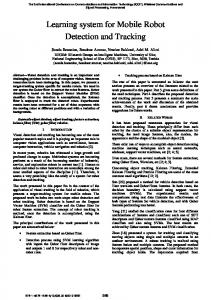
Fig. 1. The LGMD model used in the paper. There are four groups of cells and two single cells: photoreceptor cells (P); excitatory cells (E); inhibitory cells (I); summing cells (S); the LGMD cell and the feed forward cell (FFD). The input of the P cells is the luminance and output is luminance change. Lateral inhibition is indicated with dotted lines and has one frame delay. Excitation is indicated with black lines and has no delay. The FFD also has one frame delay.
A neural network model of the LGMD’s input circuitry was developed by Rind and Bramwell [13]. This model showed the same selectivity as the LGMD neuron for approaching rather than receding objects and responded best to objects approaching on collision rather than nearmiss trajectories. This model has also been used to mediate collision avoidance in a real-world environment by incorporating it into the control structure of a miniature mobile robot [14, 15]. The effectiveness (success rate) of collision avoidance control via the LGMD was always better than 69% and for half of the speeds tested it was over 90% [15]. Despite this success, there is a need to improve the reliability over wide range of speeds if it is to be used as an effective collision detector. This study will further develop the LGMD model for use as a robust collision detector in robotic applications. We propose a new mechanism to enhance the features of colliding objects before the LGMD cell gathers excitation. The new mechanism works by allowing each excited
3832
element within a cluster of excited elements to have a greater individual role in contributing to the membrane potential of the LGMD than an equivalent isolated excited element. The isolated excitations are filtered out by the excitation gathering mechanism, allowing only sections of image with large spatial areas of excitation present to contribute to the excitation in the LGMD. Experiments are carried out with a mini mobile robot to test if the new model results in more stable collision avoidance behaviour in a complex environment. II.
E f ( x, y ) = Pf ( x, y ) − I f ( x, y )WI
where WI is the inhibition weight.
LGMD MODEL
The LGMD model was based on the input organisation of the locust LGMD neuron. Each element within the network represented a process thought to occur either in the locust’s eye or on the dendritic fan of the LGMD. The LGMD model used in this study was a modified version of the model described in [13, 15 and 16]. It was composed of four groups of cells - photoreceptor, excitatory, inhibitory and summing, and two single cells - feed-forward inhibition and LGMD (Fig.1). To improve performance in robotic scenarios, a new excitation processing mechanism was added to filter irrelevant visual details for collision avoidance purposes. The first layer is the photoreceptor cells; the luminance Lf of each pixel in the input image is captured by each photoreceptor cell, the change of luminance Pf between frames of the image sequence is calculated and forms the output of this layer. The output of a cell in this layer is defined by equation: Pf ( x, y) = L f ( x, y ) − L f −1 ( x, y )
(1)
where Pf(x,y) is the change of luminance corresponds pixel (x,y) at frame f, x and y are all in pixel, Lf and Lf-1 are the luminance, subscript f denotes the current frame and f-1 denotes the previous frame. The output of the P cells forms the inputs to two separate groups of cells in the next layer. One is the excitatory cells, through which excitation is passed directly to their retinotopical counterpart in the S layer; the other is the lateral inhibition cells, which pass inhibition to their retinotopical counterpart’s neighbouring cells in the S layer with one frame delay. The strength of inhibition in this layer is given by:
Fig. 2. The schematic illustration of the excitation gathering mechanism of the LGMD cell. The pixels surrounded by strong excitations gain bigger passing coefficients and the isolated excitations get smaller passing coefficients and may be ruled out from the summing process by a threshold. The strength of excitation is indicated by grey levels where black represents the strongest excitation.
Differently from previous LGMD models that sum up all the excitation in the S units (but see [16]), we added a new mechanism for the LGMD cell to further filter background noise. The mechanism allows clusters of excitation in the S units to provide a greater individual input to the membrane potential of the LGMD neuron than the individual input of isolated S units (Fig.2). The excitation in an S unit passed to the LGMD will be multiplied by a passing coefficient Ce. The coefficient is determined by the pixel’s surrounding neighbours, i.e., defined by a convolution process 1
1
Ce f ( x, y ) = ∑ ∑ E f −1 ( x + i, y + j ) we (i, j )
(4)
i = −1 j = −1
where we(i, j) represents the influence of its neighbours and is simplified as a convolution mask,
we =
I f ( x, y ) = ∑∑ Pf −1 ( x + i, y + j ) wI (i, j ), (i = j ≠ 0) (2) i
(3)
1 1 1 1 1 1 1 9 1 1 1
(5)
j
where If(x,y) is the inhibition at pixel (x,y) at current frame f, wI(i, j) is the local inhibition weight. Unlike previous models the inhibition from the pixel (x,y) only spreads to its nearest neighbours. The excitatory flow from the E cells and inhibition from the I cells is summed by the S cells using the following equation:
The final membrane potential of the LGMD cell Sf, at frame f is then summed, as described by equation, S f = ∑∑ abs( E f ( x, y ))Ce f ( x, y )ω −1
(6)
where ω is a scale and computed at every frame by
3833
ω = max(Ce f )Cw−1 + ∆c
(7)
Cw is set to be 4, and ∆c is 0.01 to prevent ω being zero. Since Cef varies frame by frame, ω also varies at different frames. The membrane potential of the LGMD cell Sf is then normalized with the following equation, (8)
1
sf = 1+ e
−S f
A K2D video turret (K-Team, Switzerland) with a CCD was mounted on top of the robot. We used the CCD camera, to sample images in real time. The camera was working at 10 Hz in the experiment.
ncell
where ncell is the total number of the summing cells. Since Sf is greater than zero, the normalized membrane potential sf varied within (0.5~1). The membrane potential of the LGMD cell is not the final output of the neural network. The avoidance behaviour of the robot is finally decided by a spiking mechanism using an adaptable threshold [16]. The threshold Ts is started from a given value Tin and refreshed every m frames in the process, Ts + ∆t , if s av > Π and (Ts + ∆t ) ∈[Tl , Tu ] Ts = Ts − ∆t , if s av < Π and (Ts − ∆t ) ∈[Tl , Tu ] Ts , otherwise
(9)
Where [Tl , Tu] sets the lower and upper limits for adaptation, ∆t is the step of increase, Π is a threshold to measure the averaged membrane potential sav from frame fn to frame f-k, s av =
n 1 s f −i ∑ n − k + 1 i=k
(10)
If the membrane potential Sf exceeds the threshold Ts, a spike is produced. A collision is detected if there are 4 successive spikes in 4 time steps. The robot’s avoidance behaviour is initiated once collision is detected. During the avoidance behaviour, the membrane potential may go high and produce spikes because of the sudden change of visual scenes caused by the robot turning. The feed forward inhibition (FFD) works to cope with initiation of whole field movement [17]. The FFD at current frame is gathered from the photoreceptor cells with one frame delay, −1 F f = ∑∑ Pf −1 ( x, y )ncell
Fig. 3. The Khepera robot (K-team, Switzerland) and its arena used in the experiments. The diameter of the robot is 70mm. The live video from the robot’s CCD camera was processed by the LGMD model in real time and avoidance behaviours were conducted if imminent collision was detected.
(11)
Once Ff excesses its threshold, spikes in the LGMD are inhibited immediately. III. EXPERIMENT SET-UP A Khepera robot (K-Team, Switzerland) was used to test the above LGMD model. The robot was surrounded by colour plastic blocks that make an arena for it to negotiate (Fig.3). Further background of the environment was a typical laboratory and no attempt was made to hide the laboratory apparatus from the robot’s visual field.
Parameters of the LGMD model were set before the experiment. The input video images were 150 x 100 pixels, images were greyscale ranging from 0 to 255. The FFD threshold was set to 17 units. The lateral inhibition spreads to its neighbour 1 layer away and with one frame delay. The local weights wI(i, j) of the lateral inhibition are set to be 0.25 for the four nearest neighbours and 0.10 for the four diagonal neighbours. Inhibition weight WI is 0.5. The number of S cells was 15,000. The threshold of the LGMD was 0.88; ∆t was 0.0001; П was 0.72; Tl was 0.88 and Tu was 0.90. The membrane potential threshold was refreshed every 2 frames. The averaged membrane potential was gathered from f-5 to f-2 frames, that is, n is 5 and k is 2 in equation 10. During the experiment, the robot was allowed to move at a constant speed within the arena for a period of time. Once it detected an imminent collision, it stopped and rotated before continuing movement in a straight line, but on a new trajectory. The turning speed is set to be 32 mm/s for the left wheel and -32 mm/s for the right. The turning angle was controlled by time α where α = t con + λ rand (1)
(12)
tcon is a constant period of time and set to 0.5 second in the experiment, λ is a scale and set to 0.2 and rand(1) is a function generates random number between 0 to 1.
3834
The LGMD model was written in Matlab (the MathWorks, Inc., USA). The computer used in the experiment was a Dell Precision 450 with one 2.40GHz CPU. The communication between the computer and the robot was via a serial (RS232) port.
evident in the area in which the robot moved. Since most of the light was coming from windows on the right hand side of the arena, the robot tended to move predominantly in the right hand side of the arena (Fig.8), especially at higher speed (Fig.9).
IV. EXPERIMENTAL RESULTS A short robot movement period (15 seconds, speed at 32mm/s) was conducted to test and show the mechanism of the collision detector. There are two imminent collisions detected successfully at 35 and 75 frames respectively (Fig. 4; Fig.5. (a)). After each turning behaviour, the FFD inhibited spiking and prevented the robot from turning (Fig.5. (b)). Overall the membrane potential threshold increased but with several local decreases (Fig.5 (c)).
normalized membrane potential
1.5
1
0.5
0 0
50
100
150
100
150
100
150
frames
(a) 100 90
feed forward inhibition FFD
80
Fig. 4. The robot trajectory in a 15 seconds tour within the arena. The robot trajectory indicated by a bold line within the arena. Two times of collision were detected by the LGMD model and two turns were conducted. The robot is at the start position in the picture.
70 60 50 40 30 20 10
3835
0 0
50 frames
(b) 0.8845 0.884
membrane potential threshold
The normalized membrane potential reflects the complexity of the local environment the robot is facing, as shown in Fig.5 (b) [16]. It becomes more active when the robot approaches blocks and becomes less active when the robot is not close to the blocks. The membrane potential fluctuates during the movement period; however, this was probably caused by slide of the robot wheels. The isolated spikes during the movement period were also thought to result for the same reason. The excitations just before the first imminent collision are shown in Figure 6. The lines on the table caused by the grain of the wood, wires and other small objects were filtered by the new passing mechanism. This made the model more robust as it only concentrated on colliding objects. Further experiments were carried out to shown how the robot behaved within the arena at different speeds. As shown in Figures 7 - 9, it was found that at higher speeds the robot increased its distance from the blocks (Fig.9). This was because more excitation was caused by higher speeds as the change in image between successive frames was larger. However, with the lower speed (16mm/s), the robot had almost touched the object before it turned (Fig.7, first turn) as less excitation occurred due to smaller changes in successive images. The effect of light was also
0.8835 0.883 0.8825 0.882 0.8815 0.881 0.8805 0.88 0
50
frames
(c) Fig. 5. The membrane potential, the FFD and membrane potential threshold versus frames in the 15 seconds movement period within the arena. (a). The LGMD normalized membrane potential (in solid line) and spikes (indicated by stars up above the frames axis). The two times of collision detected by the LGMD model were indicated with 4 successive spikes. The burst or decline of spikes is indicated with dashed lines between zero and 1.5 on the y axis. (b). The FFD. Spikes were inhibited by the FFD around the two sharp peaks. (c). Membrane potential threshold. Robot speed was 32mm/s.
1.5
normalized membrane potential
In the above experiments, the new LGMD model demonstrated its ability to detect collisions in real time at different speeds and with real lighting conditions using only visual cues extracted from the input images. Although the Khepera robot has infrared sensors (effective range ~ 20 mm), they were not active in the experiment and the LGMD network often detected collisions from a greater distance than would be possible with the infrared sensors. The presented LGMD based collision detector relies on contrasts of the colliding objects sensed by the robot’s camera. It has the advantages and disadvantages of these contrast based methods (e.g., [6], [18]). The collision detector detects colliding objects regardless of their shapes but may fail in some situations, especially when the contrasts of colliding objects against its background are extremely low. In this case, other sensors, radar (far distance) or infrared sensor (close distance), might be helpful in increasing the robustness of the response.
1
0.5
0 0
100
200
300 frames
400
500
600
Fig. 7. (Above) the robot trajectory in a 60 seconds movement period with robot speed is at 16mm/s; the robot is at the start position in the picture. (Bottom) the LGMD membrane potential and spikes in the 60 seconds movement period; membrane potential is in solid line and spikes are indicated with stars in the upper frames axis; the burst or decline of spikes is indicated with dashed lines between zero axis to 1.5 axis.
10 20 30 40 50 60 70 80 90 100 20
40
60
80
100
120
140
10 20 30 40 50 1.5
60
80 90 100 20
40
60
80
100
120
140
Fig. 6. (Above) the excitations before the passing process at the frame that the robot detected the first imminent collision (frame no.35); one whole block and one half block get into the image. (Bottom) after the passing process at the same frame (frame no.35); most of the excitations caused by non colliding objects, such as the lines on the table caused by the grain of the wood, wires and other small objects, were filtered out with the new excitation processing mechanism. In the above scaled images, white represents the highest level of excitation in each image and pixels with negative value and zero were shown as black.
3836
normalized membrane potential
70
1
0.5
0 0
100
200
300
400
500
frames
Fig. 8. (Above) the robot trajectory in a 60 second movement period with robot speed is at 32mm/s; the robot sits at the start position in the picture. (Bottom) the LGMD membrane potential and spikes in the 60 second movement period; membrane potential is a solid line and spikes are indicated with stars in the upper horizontal axis; the burst or decline of spikes is indicated with dashed lines between zero and 1.5 on the y axis.
thank the three anonymous reviewers for their comments on the manuscript.
REFERENCES [1]. [2]. [3].
normalized membrane potential
[4].
1.5
[5].
1
[6]. [7].
0.5
[8]. 0 0
50
100
150 200 frames
250
300
350
[9].
Fig. 9 (Above) the robot trajectory in a 60 seconds movement period with robot speed is at 64mm/s; the robot begins at the position in the picture. (Bottom) the LGMD membrane potential and spikes in the 60 seconds movement period; membrane potential is in solid line and spikes are indicated with stars in the upper horizontal axis; the burst or decline of spikes is indicated with dashed lines between zero and 1.5 on the y axis.
[10].
[11].
V. CONCLUSIONS In the paper, we proposed a modified model that was based on the identified LGMD neuron in the locust brain that responds most strongly to the image of an approaching object. The model is intended as a robust and effective collision detector for autonomous robot/vehicles based applications. A new mechanism favouring grouped excitation is added to LGMD model. Experiments with a Khepera robot showed that, with the enhanced visual cues extracted by the modified collision detector, the mini robot could cruise autonomously in real time in an arena in the real world. Future work will include integration of directional sensitive neurons to extract more visual cues from the environment and improve the selectivity of the model.
[12]. [13].
[14].
[15]. [16].
[17].
ACKNOWLEDGEMENT This work is part of the LOCUST IST-2001-38097 and the support is great appreciated by the authors. We
[18].
3837
H.R. Everett, Sensors for Mobile Robots: Theory and Application. AK Peters, Wellesley, MA, 1995. M. D. Adams, Sensor modelling, design and data processing for autonomous navigation. River Edge, NJ, World Scientific, 1998. G. Indiveri. “Analog VLSI Model of Locust DCMD Neuron Response for Computation of Object Approach,’’ in Neuromorphic Systems: Engineering Silicon from Neurobiology, from the EWNS1 conference, August 1997. F.C. Rind, P.J. Simmons, “Seeing what is coming: Building collision sensitive neurons,” Trends in Neurosciences, vol.22, pp.215-220, 1999 N. Franceschini, J.M. Pichon, C. Blanes, “Bionics of visuomotor control,’’ in: T. Gomi (Ed.), Evolutionary Robotics: From Intelligent Robots to Artificial Life, AAI Books, Ottawa, 1997, pp. 49-67. N. Franceschini, “Visual guidance based on optic flow: a biorobotic approach.,’’ Journal of Physiology –Paris 98, 2004 pp.281-292. R. D. Santer, P. J. Simmons, F. C. Rind, “Gliding behaviour elicited by lateral looming stimuli in flying locusts,’’ J Comp Physiol A , 2004, in press F.C. Rind, Roger D. Santer, J. Mark Blanchard and Paul F.M.J. Verschure, “Locust’s looming detectors for robot sensors,’’ in Sensors and Sensing in Biology and Engineering, FG Barth, JAC Humphrey, and TW Secomb (Eds.), Spinger-Verlag, Wien, New York, 2003 M. O’Shea, C.H.F. Rowell, J.L.D. Williams, “The anatomy of a locust visual interneurone: The descending contralateral movement detector,” Journal of Experimental Biology, vol.60, pp.1–12, 1974. G.R. Schlotterer, “Response of the locust descending contralateral movement detector neuron to rapidly approaching and withdrawing visual stimuli,” Canadian Journal of Zoology, vol.55, pp.1372–1376, 1977. F.C. Rind, P.J. Simmons, “Orthopteran DCMD neuron: A reevaluation of responses to moving objects. I. Selective responses to approaching objects,” Journal of Neurophysiology, vol.68, pp.1654–1666, 1992. S.J. Judge, F.C. Rind, “The locust DCMD, a movement detecting neurone tightly tuned to collision trajectories,” Journal of Experimental Biology, vol.200, pp.2209–2216, 1997. F.C. Rind, and D.I. Bramwell, “Neural network based on the input organization of an identified neuron signaling impending collision,” Journal of Neurophysiology, vol. 75, pp.967– 985, 1996. M. Blanchard, P. F. M. J. Verschure, & F. C. Rind, “Using a mobile robot to study locust collision avoidance responses,” International Journal of Neural Systems, vol. 9, pp.405-410, 1999. M. Blanchard, F.C. Rind and P.F.M.J. Verschure, “Collision avoidance using a model of the locust LGMD neuron,” Robotics and Automonous Systems, vol.30, pp.17-38. 2000. Tecnical Report D11: Biological Model Report, Project IST2001-38097, LOCUST: Life-Like Object Detection for Collision-Avoidance Using Spatio-Temporal Image Processing, February 2004. R. D. Santer, R. Stafford and F. C. Rind, “Retinally-Generated Saccadic Suppression of a Locust Looming Detector Neuron: Investigations Using a Robot Locust,’’ J.R. Soc. Lond. Interface, Vol.1, 2004, pp.61-77. F. Iida, “Biologically Inspired Visual Odometer for Navigation of a Flying Robot,” Robotics and Autonomous Systems, Vol. 44/3-4, pp. 201-208, 2003.