parallelizing the collision detection sub-problem to solve it ... of research ever since robots existed. ..... When performing collision checks on voxel maps, the.
����4�,(((��3HUVRQDO�XVH�RI�WKLV�PDWHULDO�LV�SHUPLWWHG��3HUPLVVLRQ�IURP�,(((�PXVW�EH�REWDLQHG�IRU�DOO�RWKHU�XVHV��LQ�DQ\�FXUUHQW�RU�IXWXUH� PHGLD��LQFOXGLQJ�UHSULQWLQJ�UHSXEOLVKLQJ�WKLV�PDWHULDO�IRU�DGYHUWLVLQJ�RU�SURPRWLRQDO�SXUSRVHV��FUHDWLQJ�QHZ�FROOHFWLYH�ZRUNV��IRU�UHVDOH�RU� UHGLVWULEXWLRQ�WR�VHUYHUV�RU�OLVWV��RU�UHXVH�RI�DQ\�FRS\ULJKWHG�FRPSRQHQW�RI�WKLV�ZRUN�LQ�RWKHU�ZRUNV��'2,��10.1109/IROS.2014.6943148 Intelligent Robots and Systems (IROS), 2014�,((( ,QWHUQDWLRQDO�&RQIHUHQFH�RQ��SS� 4154 - 4160��14-18 Sept����4�
Unified GPU Voxel Collision Detection for Mobile Manipulation Planning Andreas Hermann, Florian Drews, Joerg Bauer, Sebastian Klemm, Arne Roennau, Ruediger Dillmann Abstract— This paper gives an overview on our framework for efficient collision detection in robotic applications. It unifies different data structures and algorithms that are optimized for Graphics Processing Unit (GPU) architectures. A speed-up in various planning scenarios is achieved by utilizing storage structures that meet specific demands of typical use-cases like mobile platform planning or full body planning. The system is also able to monitor the execution of motion trajectories for intruding dynamic obstacles and triggers a replanning or stops the execution. The presented collision detection is deployed in local dynamic planning with live pointcloud data as well as in global a-priori planning. Three different mobile manipulation scenarios are used to evaluate the performance of our approach.
I. I NTRODUCTION Complex autonomous systems typically rely on time intensive and non-agile motion planning software to achieve given objectives. This depicts a big handicap which needs to be overcome to bring mobile service robots into real life scenarios. We tackle the problem through massively parallelizing the collision detection sub-problem to solve it on General Purpose GPU (GPGPU) Hardware. In this work we first introduce the characteristics of planning data and describe the capabilities of our unified collision detection framework before we illustrate its practical application by the example of motion primitive and full body planning for our mobile manipulation platforms from Fig. 7.
than the Cartesian degrees of freedom (DOF). In contrast to that we offer the ability of reactive planning instead of low level-reflexes. The main factor that influences the computational demands of a stochastic planner is the time needed to check for self-collisions and collision with the environment. Huge progress has been made in that area through the usage of massively parallel operating GPUs in combination with treelike structures that recursively refine collision detection [3]. Most current collision detectors like the FLC [4] work with mesh-based models or approximations through geometric primitives. This approach is feasible for dealing with geometrical models, but requires time-consuming preprocessing to interpret live point cloud data. In contrary, the VPS (VoxMap Point Shell Algorithm) from [5] finds overlapping sections between a larger environment (represented by voxels) and a more detailed dynamic actor (represented by point clouds). The algorithm also exists as a GPU-accelerated version [6]. Our approach is similar to VPS as it also relies on discretisizing voxel data structures and is able to support point clouds for collision detection. The major difference is that we intersect voxels with voxels to reduce memory demands. III. T HEORETICAL AND P RACTICAL M OTIVATION
II. R ELATED W ORK Motion planning has been an intensively investigated area of research ever since robots existed. The problems to solve have become more and more demanding as today, adaptive motions are desired not only in static but also in dynamic environments. With probabilistic algorithms (RRT [1], Probabilistic Roadmaps [2]) and rising computational power, online planning becomes feasible for a significant set of problems. Also interleaved planning and execution brought robots from time-intensive sense-plan-act cycles to a more reactive behaviour. Nevertheless, most capable robots rely on behaviour-based evasion algorithms to avoid collisions, as real replanning still requires too much time if the dimension of the planning domain is significantly larger The research leading to these results has received funding from the German Federal Ministry of Education and Research (BMBF) under grant agreement no. 01IM12006C (ISABEL). All authors are with the department of Intelligent Systems and Production Engineering (ISPE - IDS/TKS) Research Center for Information Technology (FZI), 76131 Karlsruhe, Germany
{hermann,klemm,roennau,dillmann}@fzi.de
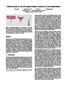
Fig. 1: Swept volume of the robot HoLLiE in a cluttered lab environment. During execution, the red volume is continously monitored for penetrating dynamic obstacles.
The vast amount of different robot motion planning algorithms is caused by the various demands of scenarios that have to be handled. This is also visible in the manifold of specialized data structures to plan within. Our choice is to use a discretizing data structure in general for collision detection in all planning scenarios (local and global), but utilize different “flavours” of memory structures to store the varying payload data.
Random Writes
Minimal Update Overhead
Random Writes
Minimal Update Overhead
Random Writes
Minimal Update Overhead
Random Writes
Minimal Update Overhead
Memory
Col.Dect.
Memory
Col.Dect.
Memory
Col.Dect.
Memory
Col.Dect.
Efficiency
Throughput
Efficiency
Throughput
Efficiency
Throughput
Efficiency
Throughput
Clearing Efficiency Sparse Coverage Efficiency
(a) Environment map
Clearing Efficiency Sparse Coverage Efficiency
(b) Robot or dynamic obstacle
Clearing Efficiency Sparse Coverage Efficiency
(c) Swept volumes
Clearing Efficiency Sparse Coverage Efficiency
(d) Motion primitives
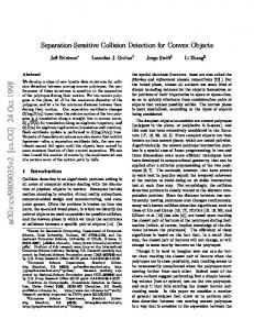
Fig. 2: Comparison of the requirements of different data characteristics from our use cases (black dashed outline) against the implemented storage structures: Voxel map (red), Octree (green) and voxel lists (blue). Compare Fig. 4.
A. Taxonomy of Memory Demands in Motion Planning Before we discuss implementation details, we characterize the data that has to be dealt with during typical planning problems and illustrate it through the following use-cases and the diagrams in Fig. 2: 1) Large sparse static structures: In many cases a robot is equipped with large maps of its environment. For real-world indoor and outdoor scenarios these maps are only populated to a very little degree and are otherwise empty. (compare Fig. 2a). 2) Highly dynamic but local structures: In contrast, a continuously shape-shifting robot model is an example for high dynamics in a limited geometric volume (compare Fig. 2b). 3) Randomly dispersed dense structures: If instead of single robot poses the whole output of a planner is aggregated in one or more trajectories (e.g. for online monitoring), these trajectories are modelled in swept volumes which densely populate a map in a random way (compare Fig. 2c). 4) Static subvolume moving in map: This occurs in Motion Primitive Planning approaches which we use in Sect. VI-B for mobile platform planning (compare Fig. 2d). The attributes we consider to describe the storage demands are: Geometrical volume which requires Memory Efficiency, if access has a random character or follows a deterministic pattern (Random Writes), the update frequency of the data (Minimal Update Overhead), the required Collision Detection Throughput, if the data is dense or sparse (Sparse Coverage Efficiency) and how fast data can be purged selectively (Clearing Efficiency). B. Throughput vs. Memory Usage With the given taxonomy in mind, we investigated our prospects for collision detection on the GPGPU. Highly parallelized programming in CUDA (Compute Unified Device Architecture by NVIDIA) requires the consideration of different programming paradigms, but in general the classical trade-off between Memory Usage and Computational Throughput is valid here, too. Therefore we analysed and prioritized the demands of planning algorithms, regarding the data they have to handle. We then chose an appropriate data storage type for the collision models.
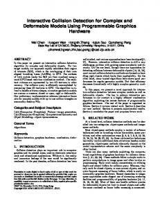
Our algorithms basically superimpose two data structures and search for regions that are populated in both. In [7] we only utilized voxel maps which already offered promising results for scenarios with limited geometrical extent. In this work we wanted to improve the collision detection throughput for larger scenarios. So we implemented different kinds of storage structures for the GPGPU architecture, which are less general than voxel maps but offer better performance for specific problems: Either they allow fast querying speed or optimized maintenance overhead during updates. A big concern was to avoid constrictions caused by bad memory coalescence or memory bottlenecks when lots of threads write and read at the same address (like a global counter). So our objective was to create structures that scale well, offer unbounded parallel read access and optimized parallel write access. As a compromise we accept minor performance losses for single collision checks, as one of the main advantages of our collision detector is the possibility to evaluate more than one configuration within one executional loop, and therefore increase total efficiency. The theoretical optimum would be a constant time for collision detection, independent of the number of investigated entities, as this would mean a linear speed up growing with the number of configurations checked in parallel. We showed in [7] that this can almost be achieved with a GPU voxel map. IV. F RAMEWORK C OMPONENTS In this section we describe the components of our system, depicted in Fig. 3. They are distributed to a CPU context (Core i7, 3.4 GHz, 32 GB RAM) and a GPGPU context (NVIDIA Titan GTX, 6 GB GDDR5 RAM and 2688 CUDA processing units for parallel execution of 86016 threads). On the CPU host side we interface with the sensors and actuators but also run the planning algorithms, while the GPU holds the robot and environment data and handles the collision detection and visualization. By running the most computationally intensive component on the GPU, the CPU of our robot stays available for real time control of the motion execution. A. Sensors for a-priori and live Environment Data Environment data is gathered in form of 3D point clouds that can be captured by various sensor types. In our experiments the a-priori maps were recorded by a rotating laser range finder and stitched together by 3D registration software
runtime the points of the links are transformed in parallel according to the results of the direct kinematic. Finally they are inserted into the robot map. Please refer to [7] for details.
Visualizer
Pointcloud Sensors
oGL-VBO
D. Motion Planner Collision Checker
Environment
Swept Volume DB
GPU Context
Robot Robot Model
Host Context
Comparison Operator
Update Operator
Planner
Robot HAL
This component interfaces with various planners, e.g. from the OMPL [9] or with our own hierarchical parallel planners. Its API allows to trigger the superposition of different maps to evaluate single poses as well as a multitude of independent poses in parallel. Also, whole motion ranges in the form of joint angles or platform poses can be queried and saved in swept volumes for a continuous observation for collisions. During parallel checks the number of distinguishable poses or swept volume subsections is only limited by the memory that is available for robot voxels. Currently we use 64 bits per voxel to identify 64 items. After planning, valid trajectories are passed to the HAL for execution. E. Visualization through Shared Memory
Fig. 3: Structure of the software components, showing the GPU parts in the blue region and all host components (CPU) in the red region. The green entities are GPU memory regions which are written by the Update Operator and interpreted by the Comparison Operator.
[8]. The clouds cover 50 × 17 × 8 m and consist of 6.6 million points. During runtime one or more RGBD cameras (Microsoft Kinect) cover the workspace of the robot and stream their data into the environment map in realtime. The process chain consists of the following highly parallelized steps: First the data is filtered in a preprocessing step to eliminate outliers before the points are transformed into the world coordinate system, where a 3D Bresenham raycasting kernel1 determines the free space between camera and object. Free and occupied voxel IDs are calculated and their Bayesian occupancy representation is updated according to a sensor specific measurement model. B. Robot Hardware Abstraction Layer (HAL) This layer is written in our MCA2 software framework2 and runs the realtime control loops for the hardware. It contains the Reflexxes3 library, which interpolates between discrete states of motion plans in a 10 ms control loop. As our framework runs on different robots, this part encapsulates the interfaces of all robot specific hardware drivers. As output it delivers joint angles and pose information from the platform localization to update the direct kinematic and therefore the geometric model of the mobile robot on the GPU. C. Robot Model The robot model consists of dense point cloud representations of the single links, which are stored statically in GPU memory. The clouds are generated offline with a raycasting algorithm that samples the volumetric CAD models. At 1A
Kernel is a function that runs with many parallel threads on the GPU and which is launched by the host. 2 Modular Controller Architecture: http://www.mca2.org 3 Reflexxes: Online Trajectory Generation http://www.reflexxes.com/
A proper visualization is an important feature which helps to retrace ongoing processes. Therefore we designed a visualization program that renders environment, robot and planning information (Fig. 1). It connects to the main program via shared memory to gain access to the collision detection data. Dedicated kernels clip the maps to the visible section and transform the according voxels and Octree leaves into triangulated cuboids. These are stored in a dynamically sized OpenGL VBO Buffer which is then rendered to the screen. The whole process works without time-consuming copying data from or to the CPU host RAM, which makes the visualizer capable to draw up to 0.5 million voxels with more than 25 FPS. Table I shows the performance for different amounts of drawn data. When collision checks and visualization are running on the same GPU, we cap the visualization to 15 FPS, to guarantee enough computational resources for collision detection purposes. Super Voxel size 1 2 8 32
Whole Num Voxels 497,567 480,686 98,407 1,792
map in VBO Num Triangles FPS 17,912K 25 17,305K 42 3,543K 89 65K 330
FOV culled voxels in VBO Num Num Voxels Triangles FPS 213,557 7,688K 50 205,570 7,401K 82 40,713 1,466K 160 630 23K 357
TABLE I: GPU visualization performance for parsing CUDA data in each frame. The level of detail can be changed by combining voxels to supervoxels. During planning, the FPS drop by about 66%.
The tool allows the user to freely move through maps of live data, switch between different maps and levels of detail (not only in Octrees but also in voxel maps) and retrieve information about clicked entities (position, affiliation, occupancy status). It is also possible to slice the shown data to e.g. cut away ceilings. V. DATA S TORAGE S TRUCTURES AND C ORRESPONDING C OLLISION D ETECTION A LGORITHMS In this section we describe the voxel storage structures which form the core of our framework. Each implemented
Random Writes
Minimal Update Overhead
Memory
Col.Dect.
Efficiency
Throughput
Clearing Efficiency Sparse Coverage Efficiency
Fig. 4: Properties of the implemented storage structures that can be matched to the use cases from Fig. 2: Voxel map (red), Octree (green), voxel lists (blue)
data structure, its specific properties and its corresponding collision detection algorithm are discussed. The voxels that we deal with hold an occupancy value and a list of affiliations, indicating to which model or swept volume they belong. So every voxel can represent many samples concurrently while it is still distinguishable which part of the robot or which section of a motion lies in collision. Apart from structure specific management information no other information is stored to keep the memory footprint as small as possible. To determine if voxels lie in collision, we compare their occupancy value with defined thresholds to avoid false positives in noisy data. A. GPU Voxel Map
Fig. 5: Environment and robot model shown in different levels of detail (1 cm, 2 cm, 4 cm voxel size). The storage can be a multi-resolution voxel map or an Octree, dependent on the planer’s requirements.
or unknown, the memory consumption increases linearly with the size of the map. One voxel is 12 Bytes in size, which defines the maximum of 265 million voxels (e.g. 940 × 940 × 300 voxels) on our hardware, as the voxel map is instantiated twice (robot planning + environment). When performing collision checks on voxel maps, the whole volume of the maps is processed. Therefore the processing time is constant and deterministic, independent of the map’s degree of clutteredness, as shown in Sect. II. Through the parallelization on the GPGPU we achieve the satisfying timings shown in Table III. To speed up collision detection, we instantiate each map several times with varying levels of detail and only query a higher level of detail, if a collision was detected in a low-resolution map. This approach is comparable to the Octree, but trades lower runtime for much higher memory requirements (the full map, and n other maps that shrink cubically per instance). The maps are generated by a scaling-copy kernel. This structure is ideally suited for use-case 2 and 3. Further details on implementation and performance can be found in [7], where we showed that maximal parallel access does not achieve the best throughput. B. Voxel Lists In case that only the voxels of a robot or its swept volume need to be represented, it is sufficient to store their addresses in an array, called voxel list. This offers huge advantages compared to voxel maps: Firstly, iterating over the list only delivers relevant data and no empty voxels have to be skipped. Secondly, it is possible to selectively query relevant regions around the robot in the environment map with the addresses from the list. This again saves the time-intensive processing of the whole environment map. Therefore we use the addressing scheme of the voxel map (see equation 1) which implicitly represent the voxels’ positions, and only store these addresses together with their lists of affiliation (currently 64 Bits per voxel) in the voxel list. The addressing scheme also allows us to translate the represented volume relatively within a map by simply adding an offset to the voxel addresses. Therefore this structure is optimal for Motion Primitive Planning from use-case 4 which will be explained in Sect. VI-B. C. GPU Octree
The data type that obviously fits the parallel architecture best is a 3D voxel map, as it consists of one large array on the GPU’s memory. When the addressing of the cells is optimized for clustered read/write access it offers unbounded parallel access to each cell within O(1). Geometric positions p = (x, y, z)T , x, y, z ∈ R are mapped to the memory addresses of according voxels VA(x, y, z) by z y x c · MDy ) + b c) · MDx ) + b c (1) B + (((b VSz VSy VSx where B is a constant memory offset calculated at program launch, VS reflects the size of the voxel in each dimension and MD holds the dimensionality of the voxel map. As voxels require memory, regardless if they are occupied, free
To reach a trade-off between memory efficiency and access time, we implemented an Octree structure. On a GPU this has to be tackled in a different way than on a CPU, because the realization of dynamically growing data structures basically contradicts the parallel programming paradigm of GPU algorithms. Dynamic memory allocation harms the data throughput profoundly, as the CUDA architecture lacks efficient memory management. We ran into that problem in our first implementation approach that excessively utilized CUDAs Dynamic Parallelism4 but performed unsatisfactorily. Therefore we accepted additional calculation costs to 4 Dynamic Parallelism: http://docs.nvidia.com/cuda/cuda-c-programmingguide/index.html#cuda-dynamic-parallelism
first determine the absolute memory demands for inserting new point cloud data into our Octree and allocate this memory at once. This is achieved by a sort algorithm that clusters the single points into voxel-sized bins and counts them. The approach exploits CUDA intrinsics and has its load balanced on the available GPU multiprocessors. The time that is needed to build up an Octree from 2 million points is 18.66 ms of which ∼ 50% is needed to transfer the data to the GPU and sort it there with radix sort. Inserting the same data into a voxel map takes 5.69 ms, but requires around ∼ 70% more memory. Cube side length [Voxels] 2 8 32 128 187
Mean num of collisions [Voxels] 0.01 0.44 37.60 1862.98 6781.29
Octree ∩ Octree [ms] 1.46 1.46 1.44 1.88 1.91
Octree ∩ Voxel list [ms] 0.10 0.10 0.11 0.41 1.04
Voxel map ∩ Voxel map [ms] 15.31 15.31 15.32 15.32 15.34
Octree ∩ Voxel map [ms] 4.21 4.20 4.28 4.71 5.61
TABLE II: Median time (100 runs) in ms for computing the collisions (∩) between an environment map and a randomly placed occupied cube with a given side length in voxels. The environment consists of 3D scans, that occupied 150.684 voxels in a map of 884 × 1004 × 187 voxels.
#Entities [leaves] / [voxels] 32K 256K 2M 16M 128M
Voxel map colcheck [ms] 0.55 0.13 0.55 3.86 17.59
Octree colcheck (incl. balancing) [ms] 1.52 2.16 3.22 5.13 21.05
Balance overhead [ms] 0.28 0.40 0.41 0.55 0.57
#Balance steps 2 2 3 3 4
TABLE III: Median time (100 runs) in ms for collision computation of fully extended Octrees and Voxel maps of different sizes. Only little balancing overhead is needed, as this is almost unnecessary in fully blown Octrees.
When an Octree has to be traversed e.g. for collision detection, the most common method is to do this in a recursive fashion: Start with the root node, descend the Octree and investigate its child nodes until a leaf node is hit or the nodes are considered free. The challenge is to highly parallelize these operations to make them suitable for GPU processing. The straightforward approach where each thread handles a node does not take full advantage of the sparse Octree representation and leads to tremendous load imbalance within a block of threads5 : Some threads have to idle instantly if at least one node is marked as free, whereas others have to traverse their subtree further. Our solution to this problem is based on the work of Lauterbach et al. who developed an efficient workload balancing approach in a similar setting [10]. The idea is to manage work queues where the threads pop/push work from/to. Imbalance between the queues is handled by a dedicated task. We improved and extended this approach to fit our needs: Our work queues have a much smaller memory footprint as each work item contains the eightfold number of operations. This originates from our Octree structure where 8 child nodes form the 5 All
threads of a block can only be managed simultaneously
smallest allocatable memory unit. Furthermore work items are processed in a way that benefits from GPU properties like memory coalescing. Also we maximized the degree of capacity utilization by using warp vote functions6 for uniform memory access and by resigning the use of large local workqueues in shared memory. Algorithm 1 shows our heuristic balance task which distributes work faster and more evenly among work queues as it takes advantage of the GPU’s high memory throughput (288.4 GB/s). Its input are work queues whose items meet the depth-first sort sequence. This means that the depth of the subtree (and therefore its assumed work load) implied by the work item’s nodes gets smaller from bottom to top end of the queue. The heuristic balance task then distributes the work evenly in layers by size among the work queues. Afterwards each work queue still meets the depth-first order sorting, but each block of threads works on tasks with similar runtime. Considering the memory throughput this solution performs better than voxel maps for sparse contents as seen in Table II. Even when intersecting two fully extended maps, an Octree with a size of 128 million voxels reaches 128 · 4 · 2 · MB/0.0211 s ≈ 47.4 GB/s. That is 80 % of the collision detection performance of our voxel map implementation. Therefore the Octree is the ideal candidate to represent real-world environments from use-case 1, as they are only sparsely populated. Algorithm 1 Balance Work Queues Require: Sin [n] : WorkItem, each Stack Sin [i] fulfills ∀1 ≤ i < n | level(S[i − 1]) ≥ level(S[i]) Ensure: Sout [n] : WorkItem, each Stack Sout [i] fulfills “require” \\ count step 1: C[0 : #level − 1][0 : n − 1] ← {0 . . . 0}, I[0 : n − 1][0 : #level − 1] ← {0 . . . 0} 2: for i ← 0, n − 1 do \\ in parallel 3: S ← Sin [i], S[0 : #level − 1] ← {0 . . . 0} 4: for j ← tid, size(S) − 1, j ← j + #threads do \\ in parallel 5: S[ level(S[j]) ] += 1 \\ atomic increment 6: end for 7: for j ← tid, #level − 1, j ← j + #threads do \\ in parallel 8: C[ #level − l − 1 ][i] ← S[j] 9: end for 10: I[i] ← suf f ixSum(S) 11: end for 12: C ← pref ixSum(C) \\ in parallel \\ move step 13: for i ← 0, n − 1 do \\ in parallel 14: S ← Sin [i] 15: for j ← tid, size(S) − 1, j ← j + #threads do \\ in parallel 16: l ← level(S[j]) 17: p ← C[ #level − l − 1 ][i] + (j − I[i][l]) \\ target position 18: Sout [ p mod n ][ p/n ] = S[j] 19: end for 20: end for
D. Planning and Monitoring with Swept Volumes Free space within the maps has to be explicitly marked as such. This counts for dynamic obstacles in the environment map, which are cleared by raycasting as mentioned in Sect. 6 Warp Vote Functions: http://docs.nvidia.com/cuda/cuda-c-programmingguide/index.html#warp-vote-functions
be shared with human workers. The robot is equipped with RGBD sensors to move safely in this unstructured environment. We will explain our strategies for the occurring planning problems and our choice of storage structures in the following sections. A. Whole Body Planning with high DOF (a)
(b)
(c)
(d)
Fig. 6: Swept volumes: (a) Motion Samples for motion primitive platform planning, showing a rotational sweep that is in collision and (b) one that is restricted to be collision free. Typical motion to bring the manipulator from the inward folded driving pose to a manipulation pose: (c) Simulated model, (d) generated volume, used for conservative platform motion planning during the start and approach phase.
IV-A, but also for the robot which has to be removed from the map after planning. However, if the interpolated poses of a successful planning step are kept in the map (see Fig.1), the whole trajectory can be monitored for dynamic obstacles intruding its volume. As mentioned earlier, checking not only single motion samples but whole trajectories is essential to fully exploit the capabilities of our hardware. So, investigating trajectories represented by swept volumes is not to be regarded as computationally expensive operation, like in conventional mesh-based collision detectors, but as a highly desirable feature. If a sweep is segmented, also the approximate position of a collision can be determined and used to inform a planner. This approach was extensively investigated in our previous work [7]. Storing swept volumes of motion-sub-plans in voxel lists allows highly efficient motion-primitive planning, as whole trajectories can be evaluated at different positions within the environment map within one collision detection step. This is exploited in Sect. VI-C. VI. E VALUATION T HROUGH A PPLICATION IN M OTION P LANNING
Fig. 8: Evaluation scenario for a whole body planning problem with 15 DOF (Start, goal, planned motion). A plan was found after 7.7 sec. in average, smoothing took another 2.1 sec.
Products have to be put into storage slots of mobile trays, which are placed at indeterministic positions. Free slots will be visually located by the robot in 6D. We chose to employ a full body planning for this scenario: Planning the 15 DOF of our robot is realized with the RRT* implementation of the OMPL. The collision check is carried out between voxel maps with a 4 cm resolution of the robot’s proximity and of the robot’s geometry (example scenario shown in Fig. 8). The search space is limited by restricting platform poses to the proximity of the target tray. Over 25 evaluation runs we gathered the following results: In average 7169 collision checks were performed (Min: 103, Max: 38240), which took 7.719 sec. (Min: 0.127 sec., Max: 40.997 sec.). and resulted in an average planning time of 7.795 sec. (Min: 0.128 sec., Max: 41.554 sec.). Smoothing required ∼ 2.1 sec. In average, a single collision check of the whole robot model (37862 voxelized points) against 3.2 million environment voxels took only 0.001 sec. B. Mobile Platform Planning with Motion Primitives
Fig. 7: The highly articulated mobile robots IMMP [11] (Industrial Mobile Manipulation Platform) and HoLLiE (House of Living Labs Intelligent Escort) [12] that plan their motions with the presented collision detection.
The application scenario for a one-arm version of the robot IMMP (Fig. 7) is the manufacturing site of a chip producing company where different machines have to be loaded and unloaded. The workspace is limited, cluttered, and has to
For mobile platform planning, we use a motion primitive approach with voxel lists as robot representation. Gridbased planning is sped up through rotational sweeps of the robot, which are evaluated within an Octree representation of the environment (see Fig. 9). To support arm motions during the accelerating and approach phases of the platform, an extended sweep including the arm’s trajectory is used, while a sweep with inward folded arm is used for the distance in between (see Fig. 6). A D*-Lite planner allows rapid replanning in case of new emerging obstacles. This combination outperforms a state of the art RRT-Connect planner in cluttered scenarios: We could generate smooth high resolution platform plans in 0.3223 sec while the RRT needed 0.979 sec. This allows an online replanning around dynamic obstacles without having to stop the robot. Details can be found in [13].
Fig. 9: Platform planning shown from top. Planner evaluates rotational swept volumes (see Fig. 6) and builds an optimized path of samples with overlapping feasible rotations.
Fig. 10: Left: Mobile platform navigating in a point cloud via motion primitive planning. Right: RRT planning with 10 DOF in simulation.
C. Determination of Applicable Platform Poses for Manipulation Tasks When an object has to be picked up or placed a at given position, two problems have to be solved: Planning an arm motion to handle the object and moving the platform to a suitable approach pose for the manipulation task. We solve this by combining swept volume collision detection for the arm while planning the platform path via motion primitives, as seen in Fig. 11. By pre-computing and inflating the volume that is needed by the arm for typical picking or placing actions, we can efficiently determine if manipulation poses are valid and use those as goals for the platform planner without simulating the arm motions itself at each pose. That way 64 different platform poses (including arm trajectories) can be evaluated with one collision check in ∼ 0.001 sec.
Fig. 11: Six possible grasp poses. The planner chooses an alternative manipulation pose after new obstacles were found. Evaluating a new pose including the arm motion is done with only one single collision check.
VII. C ONCLUSIONS We illustrated the characteristics of various kinds of data that occur in mobile manipulation planning through a taxonomy and implemented three different data structures matching the determined demands. All structures are optimized
for being processed in parallel on GPGPU hardware. For planning and monitoring robot trajectories efficiently, we developed highly parallelized collision detection algorithms, that can superimpose each datatype with all others and can deal with live point cloud data. Our implementation of a large dynamic data structure (Octree) is pushing the state of the art in GPU-usage for robotic applications, as it outperforms CPU based solutions like Octomap [14] regarding the querying and update speed. Finally we combined the Octree with our previous work from [7] and [13] to a unified GPU based collision detection framework and demonstrated its capabilities in three different planning scenarios. In the future we will further investigate and improve planning performance for high DOF problems and optimize the interaction between OMPL planners and our parallel collision detection. Also we will work on online swept volume based grasp planning for multi-fingered hands. The presented software is available OpenSource on http://www.gpuvoxels.org/. R EFERENCES [1] S. M. Lavalle, “Rapidly-exploring random trees: A new tool for path planning,” Tech. Rep., 1998. [2] L. Kavraki, P. Svestka, J. claude Latombe, and M. Overmars, “Probabilistic roadmaps for path planning in high-dimensional configuration spaces,” in IEEE International Conference on Robotics and Automation, 1996, pp. 566–580. [3] J. Pan and D. Manocha, “GPU-based parallel collision detection for fast motion planning,” vol. 31, no. 2. Thousand Oaks, CA, USA: Sage Publications, Inc., Feb. 2012, pp. 187–200. [4] J. Pan, S. Chitta, and D. Manocha, “FCL: A general purpose library for collision and proximity queries,” in Robotics and Automation (ICRA), 2012 IEEE International Conference on, 2012, pp. 3859–3866. [5] W. McNeely, K. Puterbaugh, and J. Troy, “Six Degree-of-Freedom Haptic Rendering Using Voxel Sampling,” in Proceedings of ACM SIGGRAPH 99, 1999, pp. 401–408. [6] F. Zheng, W. Feng Lu, Y. San Wong, and K. Weng Chiong Foong, “Graphic processing units (GPUs)-based haptic simulator for dental implant surgery,” 2013. [7] A. Hermann, S. Klemm, Z. Xue, A. Roennau, and R. Dillmann, “GPU-based Real-Time Collision Detection for Motion Execution in Mobile Manipulation Planning,” in 16th International Conference on Advanced Robotics, ICAR 2013, 2013. [8] J. Oberl¨ander, S. Klemm, G. Heppner, A. Roennau, and R. Dillmann, “A multi-resolution 3-d environment model for autonomous planetary exploration,” in IEEE International Conference on Automation Science and Engineering, 2014. [9] I. A. S¸ucan, M. Moll, and L. E. Kavraki, “The Open Motion Planning Library,” IEEE Robotics & Automation Magazine, vol. 19, no. 4, pp. 72–82, December 2012, http://ompl.kavrakilab.org. [10] C. Lauterbach, Q. Mo, and D. Manocha, “gProximity: Hierarchical GPU-based operations for collision and distance queries,” in Computer Graphics Forum, vol. 29, no. 2. Wiley Online Library, 2010. [11] A. Hermann, Z. Xue, S. Ruehl, and R. Dillmann, “Hardware and software architecture of a bimanual mobile manipulator for industrial application,” in Robotics and Biomimetics (ROBIO), 2011 IEEE International Conference on, dec. 2011, pp. 2282 –2288. [12] A. Hermann, J. Sun, X. Zhixing, S. Ruehl, J. Oberlaender, A. Roennau, J. Zoellner, and R. Dillmann, “Hardware and Software Architecture of the Bimanual Mobile Manipulation Robot HoLLiE and its Actuated Upper Body,” in Advanced Intelligent Mechatronics (AIM), 2013 IEEE/ASME International Conference on, jul. 2013, pp. 286 –292. [13] A. Hermann, J. Bauer, S. Klemm, and R. Dillmann, “Mobile manipulation planning optimized for GPGPU Voxel-Collision detection in high resolution live 3d-maps,” in Conference ISR ROBOTIK 2014, Munich, Germany, June 2014. [14] A. Hornung, K. M. Wurm, M. Bennewitz, C. Stachniss, and W. Burgard, “OctoMap: An efficient probabilistic 3D mapping framework based on octrees,” Autonomous Robots, 2013.