PROCEEDINGS OF SYMPOL 2009
A Command Driven DSP Hardware for DOA Estimation Ananthakrishnan V., Sujith Mathew, Supriya M.H. and P. R. Saseendran Pillai Department of Electronics, Cochin University of Science and Technology, Kochi – 682 022, India.
[email protected],
[email protected],
[email protected],
[email protected] Abstract: Techniques for the localization and tracking of noise sources in the ocean using passive listening mechanisms are being evolved by estimating the direction of arrival of the noise waveform at two or more distinct positions using buoy systems. This paper introduces a command driven signal processing hardware for obtaining the direction of arrival of noise waveforms emanating from the target under consideration, working concurrently with a 20 element hydrophone array, which is mechanically steered by a hydrophone array controller. This subsystem computes the signal power of a source, within a user selectable band of frequencies. The hardware can be set for various gains, bandwidths and integration cycles. Keywords: DSP hardware, Direction of Arrival Estimation, Hydrophone Array Controller
1. Introduction Underwater surveillance systems depend mostly on acoustic signals. These signals may be either generated from the target of interest, or from the surveillance system itself. One of the main requirements of most surveillance systems is the precise position fixing and ranging of targets, which are implemented mostly using various algorithms on real time data from such systems. Systems that track noise sources compute the position, usually by generating angular information, by finding the direction of arrival of the noise and processing it with well known techniques. One such technique commonly used is the triangulation method, which can pinpoint an unknown source using angular positional data obtained from the vertices of a known triangle. This paper discusses a command driven hardware interface to a 20 element linear hydrophone array, to estimate the direction of maximum
978-1-4244-9118-6/09/$26.00 ©2009 IEEE
signal arrival for localization and tracking applications, using DSP techniques.
2. Methodology Position fixing and ranging of a target requires a hydrophone array with fairly good directivity which can be steered in the horizontal plane. The spectral power of the target noise waveform captured by the hydrophone array is computed in all directions separately to obtain a pattern of signal strength variations. This pattern can be analysed to find the direction of maximum signal arrival. This paper discusses the work carried out on a Power Estimator, forming a subsystem working in conjunction with a Hydrophone Array Controller, which initiates actions and communications through predefined commands. The main controller handles the beam steering and data analysis, as well.
184
PROCEEDINGS OF SYMPOL 2009
Beam steering is achieved by mechanically rotating the hydrophone array by the Hydrophone Array Controller (HAC). Communication and control of the HAC by a remote shore station is carried out through an RF link. Since the system is designed to work remotely, solar power source working in conjunction with storage cells and a power management unit are used along with the HAC hardware. The spectral power of the noise waveform emanating from the target is estimated using a DSP enabled microcontroller with built-in peripherals for analog to digital conversion and data communication. This part of the hardware is responsible to respond to valid commands received through the communication peripherals and performing the spectral power estimations.
3. Beam Steering The three meter long linear hydrophone array is immersed underwater using a 40mm stainless steel shaft, 6 meters long, connected to a gearbox with worm-gear arrangement driven by a brushless DC motor. The whole setup is kept afloat on the platform of a buoy. The motor is controlled by a driving circuitry built with the hydrophone array signal controller using its built-in motor control PWM (Pulse Width Modulation) module. Angular position of the array is fed back from a shaft encoder which makes use of Hall Effect switches of the BLDC (Brush-Less DC) motor, reducing the complexity and cost. Optical proximity limit switches are attached to the anticlockwise and clockwise limits which are 720° apart, so that the encoder can make absolute reference of the angles and prevent the hydrophone array cable from entangling on the shaft setup. A digital compass attached to the dry end of the shaft feeds back the beam direction with reference to the magnetic axis of the Earth.
Acoustic signals received by the hydrophone array are amplified by the internal preamplifier of the array. Specialized hardware is used to condition and process this signal to estimate the direction of arrival, as described in latter sections of this paper.
4. Power Computing Hardware The analog input of the 20element hydrophone array is directly coupled to the power computing hardware. The array carries within itself an internal amplifier, powered through external circuits, so that the amplified signals can be transmitted from the array to the receiving side, which helps in reducing the noise effects. The array is designed to work on 6.8VDC, with a simple driving circuit. The signals from this driving circuit are directly fed to the preamplifier and signal conditioner of the power computing hardware. The block diagram of the analog section of the power computing hardware is shown in Figure 1. Signals from 20-element Hydrophone Array
Pre Amplifier
Signal Conditioner
Hydrophone Array Controller
Other subsystems
Power Computing System
Fig. 1 Block Diagram of the Power Computing Hardware Signals from the hydrophone array need to be amplified to the dynamic range of the built-in ADC of the microcontroller. The output from the hydrophone pre amplifier is an inverted signal varying from a few micro volts to millivolts, depending on the source level of the noisy target. A level shifting, amplification and filtering must be performed on this signal to generate a compatible signal for the ADC. Since the signal processing module has a
185
PROCEEDINGS OF SYMPOL 2009
bandwidth of 0~5 kHz, higher frequencies can cause problems like aliasing in DSP operations. Hence, a fifth order Butterworth filter has been implemented in hardware. The filter has been built in 3 stages, two of which are second order Butterworth filters in Sallen-Key topology, while the third stage is an inverting active low pass filter of first order. The analog section of the power computing hardware is built around a low power, matched quad op amp IC. The input and output parameters for all the four stages are matched. The Unity Gain Bandwidth product of each amplifier is 3 MHz, with a slew rate of 13V/µs. The CMRR and PSRR values are above 70dB. The op amp also features high impedance JFET inputs and short circuit protection at the output, rendering it fit for the proposed application.
4.1.
The Preamplifier
A typical AC coupled inverting amplifier with a fixed voltage gain of 30 has been used as the preamplifier. This stage is meant to match the output of the internal amplifier of the hydrophone, and provide sufficient gain for further signal processing. Simple low-pass filter is also incorporated with the preamplifier to band limit the signal and provide a latch up free operation.
4.2.
The Signal Conditioner
A Butterworth filter was chosen for signal conditioning, as it features a steady roll off curve while giving a decently steep stop band slope. The signal conditioner has been designed to have a typical roll off of -15dB. The whole design works on a 5V supply, with a virtual bias on 2.5V, which eliminates the need for dual supplies, and complies with the input of the ADC. The output of the signal conditioner is DC coupled, and can be directly coupled to the input of the ADC. Protection diodes have been provided to the input and output of the signal conditioner for handling overload situations.
4.3.
The DSP hardware
The computation of power within the selected band of frequencies is performed using a DSP enabled 16-bit microcontroller. The microcontroller has a maximum throughput of 30 MIPS and has many integrated peripherals, including a 12 bit ADC with a maximum conversion rate of 100 Ksps and two UART modules. The processor is configured to run on an internal RC oscillator at 14.74 MHz. The ADC module is configured to operate at a sampling rate of 10.24 ksps, giving a bandwidth of 5.12 kHz. The UART module in the DSP controller is configured to operate at 9600 baud, making it compatible for communicating with the hydrophone array controller. Normally, the DSP hardware is in power down mode, until data capture or surveillance operations are initiated through the command interface. Upon reception of a valid command, the ADC begins sampling the output of the signal conditioner, and records samples of 100 ms duration in a buffer. When this buffer is full, the 12-bit integer data is converted to double precision values and transferred to a separate buffer for further processing. An FFT is performed on this data, and the results are used to compute the power in the desired band of the signal.
5. DOA Estimator Software The heart of the DOA Estimator is the microcontroller based power computing software which performs various procedures, based on user selectable parameters. The Hydrophone Array Controller issues the commands to the power computing hardware through the built-in UART of the microcontroller. The software recognizes six commands, each one for the spectral power estimation and averaging count, selecting the gain, selecting the upper and lower cutoff
186
PROCEEDINGS OF SYMPOL 2009
frequency of the desired spectrum, for extracting the previous direction of maximum signal arrival and step angle respectively. Each command results in responses which specify the actions already initiated.
5.1.
Program Structure
built-in peripherals and variable declarations and buffer initializations before sending the device to power down mode. Wake up interrupts for ADC and UART are also enabled, so that the device can wake up from the power down mode, on receiving interrupts from either of the peripheral modules.
The microcontroller program is divided into three threads, namely the main thread, the UART interrupt and the ADC interrupt. In line with the power management considerations, the power Estimator hardware is required to consume least power possible. Hence the hardware is kept in power down mode unless any surveillance operation is being undertaken. Powering down the hardware during ADC conversion enhances the performance of the ADC peripheral by minimizing clock switching that can cause HF noises. All the three threads are terminated in a power down mode, and run mainly on interrupt based routines. A flowchart showing the three threads are depicted in Figure 2.
5.1.2. The UART Interrupt The built-in UART module receives and transmits predefined commands and responses respectively. The reception of the module is interrupt enabled, and hence, every reception causes an interrupt, which can even wake up the controller from power down mode, if required. On receiving a valid command block, this thread identifies and verifies the validity of the command, and extracts the parameters from the block, while initiating necessary actions like changing the variable values and activation of the ADC. The transmit section of the software has a well defined polling strategy, and generates no interrupts.
5.1.1. The Main Thread The main thread of the power computing software performs a set of initializations for the
5.1.3. The ADC Interrupt The ADC module is activated within the UART Interrupt thread, when requested by commands that need signal samples from the ADC Samples Ready
Rx at UART
Start
Copy to Input Buffer Is CMD Valid? Buffer Full?
Initialize Peripherals Obtain Parameters Initialize Buffers
Copy to Process Buffer Enable Interrupts
Is ADC required?
Enable ADC Compute Spectral Power
Power Down Execute Command
Initiate Start of Conversion
Stop
Averaging Complete?
Return ACK Output Result Power Down
Power Down
Fig. 2 Flowchart of the Power Computing Software
187
PROCEEDINGS OF SYMPOL 2009
hydrophone array. The built-in ADC module of the controller has a 16 word buffer and the ADC interrupt thread is activated when one half of the buffer is filled with new values by the ADC module. On every interrupt, eight ADC words are copied into the 512 word long input buffer of the controller. After 64 such interrupts, a procedure in the main program, which copies the input buffer to the FFT process buffer, is invoked and the FFT of this array is computed. Meanwhile, if averaging has been requested, the ADC Interrupt thread is simultaneously activated without hindering any of the FFT computations. Once the computations are complete, the necessary response is formatted and sent to the main controller through the UART transmit function.
6. Approach All the operations including powering up the HAC can be handled remotely. When the power is up, the HAC initially aligns the array to a position which is 360° away from both clockwise and anticlockwise rotational limits. The system is now ready to begin the surveillance operations. The remote station can now request the HAC for a spectral power computation, which is carried out in the power computing controller. The spectral power is then transferred to the remote station along with the GPS reading of the HAC and the alignment angle of the array with reference to the magnetic axis of the Earth. Since the HAC is responsible for all remote communications, it remains active even if the battery power level is critically low. Under extremely low battery conditions, the HAC shuts down itself, and all communications with the remote station are relinquished till power is replenished.
7. Performance Evaluation The preliminary performance evaluation of the system was carried out using audio sources and pre-recorded noise data directly fed into the hardware. The main controller was
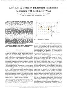
mimicked using the COM port of a PC and a COM port emulation program. A separate command for verifying the spectral data was added to the system, such that, the hardware responds by sending the 512 points of the power spectrum. The spectral results were satisfactory. Power of prerecorded noise sources was computed and very good results were obtained, one of which is depicted in Figure 3. Later validation tests were also carried out in the Underwater Test Facility with power amplifier and standard underwater projector, keeping the hydrophone array immobilized and varying the position and amplitude of noise source. Subsequently, the field trials of the system were carried out in an Underwater Acoustic Research Facility in a reservoir and the estimation of direction of arrival yielded quite encouraging results like the one depicted in Figure 4. DOMA of an idling barge 340
0
350
10
20
330
30
320
DOMA at 39° 40
310
50
300
60
290
70
280
80
270
90
260
100
250
110
240
120 230
130 220
140 210
150 200
190
180
170
160
Fig 4: Direction of Arrival of an idling Barge Engine estimated using the DOA Estimator
8. Results and Discussion The direction of arrival of the noise waveforms emanating from the Barge Engine was estimated using the DOA Estimator in an Underwater Acoustic Research Facility in a reservoir and the DOA was seen to be 39° with reference to the magnetic meridian.
188
PROCEEDINGS OF SYMPOL 2009
The power estimator yielded encouraging results under field trials in an environment, which minimizes the possibility of reflections. During the field trials, the power estimator was sensitive even to the unavoidable noises on the testing platform, when averaging was not used. The FFT code used for the power computation takes 220 ms to complete the task, which even though does not affect the result much, can be easily reduced to less than 100ms by increasing the processor frequency, causing heating issues, which has to be suitably dealt with.
9. Conclusions The Power Computation Module has been realized and field tested with a hydrophone array controller. The estimator is capable of reporting the absolute angle with reference to the Earth’s magnetic meridian during the field trials. Two or more of power estimators in known positions, can help in fixing the position and ranging of underwater noise sources and targets of interest. The absolute ranges and positions of targets depend on the precision of GPS data and magnetic compass readouts [1].
ACKNOWLEDGEMENTS The authors gratefully acknowledge the Department of Electronics, Cochin University
of Science and Technology for providing the facility to carry out this work and the Department of Information Technology (Govt. of India) for the financial assistance.
References [1].
A. Alcocer, P. Oliveira, and A. Pascoal. “Underwater Acoustic Positioning System based on Buoys with GPS” Proceedings of 8th European Conference on Underwater Acoustics, Portugal, 12 June 2006.
[2].
http://ww1.microchip.com/downloads/ en/DeviceDoc/70143C.pdf- Microchip dsPIC30F6014A datasheet
[3].
http://www.national.com/an/AN/AN31.pdf - Application Note 31 Op Amp Circuit Collection
[4].
http://focus.ti.com/docs/prod/folders/p rint/tl084.html TL084 Datasheet
[5].
B. Somanathan Nair, Digital Signal Processing Theory, Analysis and Digital-filter design, Prentice-Hall, India 2006
[6].
http://local.wasp.uwa.edu.au/~pbourke /miscellaneous/dft/ Fast Fourier Transform by Paul Bourke, June 1993.
189