materials Article
A Comparative Study on Permanent Mold Cast and Powder Thixoforming 6061 Aluminum Alloy and Sicp/6061Al Composite: Microstructures and Mechanical Properties Xuezheng Zhang, Tijun Chen *, He Qin and Chong Wang State Key Laboratory of Advanced Processing and Recycling of Nonferrous Metals, Lanzhou University of Technology, Lanzhou 730050, China;
[email protected] (X.Z.);
[email protected] (H.Q.);
[email protected] (C.W.) * Correspondence:
[email protected]; Tel.: +86-931-2976-573; Fax: +86-931-2976-578 Academic Editor: Mark Whittaker Received: 24 April 2016; Accepted: 18 May 2016; Published: 24 May 2016
Abstract: Microstructural and mechanical characterization of 10 vol% SiC particles (SiCp ) reinforced 6061 Al-based composite fabricated by powder thixoforming (PTF) was investigated in comparison with the PTF and permanent mold cast (PMC) 6061 monolithic alloys. The results reveal that the microstructure of the PMC alloy consists of coarse and equiaxed α dendrites and interdendritic net-like eutectic phases. However, the microstructure of the PTF composite, similar to that of the PTF alloy, consists of near-spheroidal primary particles and intergranular secondarily solidified structures except SiCp , which are distributed in the secondarily solidified structures. The eutectics amount in the PTF materials is distinctly lower than that in the PMC alloy, and the microstructures of the former materials are quite compact while that of the latter alloy is porous. Therefore, the PTF alloy shows better tensile properties than the PMC alloy. Owing to the existence of the SiC reinforcing particles, the PTF composite attains an ultimate tensile strength and yield strength of 230 MPa and 128 MPa, representing an enhancement of 27.8% and 29.3% than those (180 MPa and 99 MPa) of the PTF alloy. A modified model based on three strengthening mechanisms was proposed to calculate the yield strength of the PTF composite. The obtained theoretical results were quite consistent with the experimental data. Keywords: powder thixoforming; permanent mould cast; SiCp /6061Al composite; microstructure; tensile properties; strengthening mechanisms
1. Introduction Developing low density, high specific stiffness and super dimensional stability materials have always attracted considerable attention for aerospace and automobile industrial applications [1,2]. Aluminum matrix composites (AMCs) reinforced with ceramic particles are particularly attractive because of their superior strength, stiffness and wear resistance. In addition, they have excellent isotropic mechanical and physical properties both at ambient and elevated temperatures in comparison with the conventional monolithic alloys [1]. One main problem still always plagues the incorporation of micro-size ceramic particles into the aluminum matrix: the high clustering tendency of micro-particles [3]. Numerous methods have been developed to overcome this problem such as melt stirring [2,3], ultrasonic dispersion [4], squeeze casting [5,6] and powder metallurgy [7,8]. Among the various processing techniques, powder metallurgy has prominent advantages such as flexible design of the constituents and uniform distribution of ceramic particles [8], but the as-obtained composites inevitably comprise numerous voids, though some advanced sintering techniques are Materials 2016, 9, 407; doi:10.3390/ma9060407
www.mdpi.com/journal/materials
Materials 2016, 9, 407
2 of 16
employed. Besides, it is not suitable to apply powder metallurgy to produce parts with large sizes or complex shapes [7]. Materials 2016, 9, 407Thixoforming, a promising metal-forming technology that can markedly2 diminish of 16 voids, has been introduced to be integrated with powder metallurgy and thus a novel technology called techniques are employed. Besides, is not suitable to apply powder metallurgy to produce PTF is developed. The PTF not onlyitretains the advantages of powder metallurgy, butparts alsowith inherits large sizes or complex shapes [7]. Thixoforming, a promising metal-forming technology that can the merits of compact microstructure and being available for producing large-sized and complicated markedly diminish voids, has been introduced to be integrated with powder metallurgy and thus a components of the thixoforming. Unfortunately, the focus of the existing research into PTF was mainly novel technology called PTF is developed. The PTF not only retains the advantages of powder on the microstructure partial remelting and mechanical properties of aluminum metallurgy, but alsoevolution inherits theduring merits of compact microstructure and being available for producing matrix alloys [9–11]. Only a fewcomponents studies involved composites fabricated by PTF, and they large-sized and complicated of the thixoforming. Unfortunately, the focus of theconcentrated existing on theresearch effects brought by mainly solutionon treatment [12] or failed to consider the corresponding mechanical into PTFout was the microstructure evolution during partial remelting and mechanical properties [13]. properties of aluminum matrix alloys [9–11]. Only a few studies involved composites fabricated PTF, and the effects out byofsolution treatment [12] or and The main by purpose ofthey this concentrated study is to on highlight thebrought advantage this novel technology failed to consider the corresponding mechanical properties [13]. elucidate the strengthening mechanisms of SiCp in the PTF-SiCp /6061Al composite. To achieve this The10 main purpose is to highlight the advantage of this novel technology and goal, several vol% of 6.94 of µmthis SiCstudy p reinforced 6061 Al-based composite samples were prepared using elucidate the strengthening mechanisms of SiCp in the PTF-SiCp/6061Al composite. To achieve this PTF, and the resulting microstructure, mechanical properties and fracture behavior were investigated goal, several 10 vol% of 6.94 µm SiCp reinforced 6061 Al-based composite samples were prepared in detail in comparison with those of the matrix alloys fabricated by PMC and PTF, respectively. using PTF, and the resulting microstructure, mechanical properties and fracture behavior were A modified modelinon the basis of three strengthening mechanisms wasfabricated proposedbytoPMC calculate the yield investigated detail in comparison with those of the matrix alloys and PTF, strength of this composite. The obtained theoretical results were found to be quite consistent respectively. A modified model on the basis of three strengthening mechanisms was proposedwith to the experimental data. calculate the yield strength of this composite. The obtained theoretical results were found to be quite consistent with the experimental data.
2. Materials and Methods 2. Materials and Methods
2.1. Fabrication PMC of 6061 Alloy 2.1. Fabrication PMC of 6061 Alloy
The PMC-6061 alloy employed in this work was prepared by pure Al, Mg, Cu and Al-20Si master PMC-6061 employed this work was prepared by pure Al, Mg, Cu andthe Al-20Si masteralloy alloy (all The of them werealloy provided byinChangfeng factory, Lanzhou, China) and resulting alloy (all of them were provided by Changfeng factory, Lanzhou, China) and the resulting possessed a nominal composition of Al-1.0Mg-0.6Si-0.3Cu (wt%). A schematic illustration ofalloy the PMC possessed a nominal composition of Al-1.0Mg-0.6Si-0.3Cu (wt%). A schematic illustration of the PMC process is presented in Figure 1. First, a quantity of the master alloy and pure metals was melted in process is presented in Figure 1. First, a quantity of the master alloy and pure metals was melted in a a resistance furnace at 1023 K. Degassing was then conducted at 1003 K by adding 1.5 wt% C2 Cl6 resistance furnace at 1023 K. Degassing was then conducted at 1003 K by adding 1.5 wt% C2Cl6 (Kejia (KejiaChemical Chemical Company, Ningbo, China) melt. 5 min ultimately Company, Ningbo, China) intointo the the melt. The The meltmelt was was heldheld for 5for min and and ultimately injected into a permanent mold (Changfeng factory, Lanzhou, China) with diameters of 50 injected into a permanent mold (Changfeng factory, Lanzhou, China) with diameters of 50 mm mm and and lengths of 500 mm. Some specimen cakes with diameters of 50 mm and lengths of 15 mm were lengths of 500 mm. Some specimen cakes with diameters of 50 mm and lengths of 15 mm were cut cut the cast rods. from from the cast rods.
Figure 1. Schematic illustration of the PMC and PTF process (m: matrix; p: SiCp).
Figure 1. Schematic illustration of the PMC and PTF process (m: matrix; p: SiCp ).
2.2. Fabrication PTF of Sicp/6061 Composite and 6061 Alloy The raw materials used in the fabrication of SiCp /6061 composite and 6061 alloy were atomized 6061 alloy powders and pre-oxidized SiC particles with an average size of 17.91 µm and 6.94 µm,
Materials 2016, 9, 407
3 of 16
respectively. For comparison, the schematic diagram of the PTF process for SiCp /6061 composite is also presented in Figure 1. First, 6061 alloy powders were mixed with 10 vol% SiCp and the resulting powders were subjected to ball milling in an ND7-21 planetary ball-milling machine (Nanjing Laibu Technology Industry Co., Ltd., Nanjing, China) at a mixing time, rotation speed and ball-to-powder weight ratio of 40 min, 100 rpm and 5:1, respectively. The resultant powder mixture was then cold pressed into a specimen with 50 mm in diameter and 15 mm thickness under a pressure of 150 MPa. Based on the results of an existing research [14], one specimen was heated in a resistance furnace at 933 K for 90 min. Then the heated specimen was quickly put into a forging mold (Changfeng factory, Lanzhou, China) with a cavity 55 mm in diameter and 45 mm deep, and finally thixoformed under an optimized pressure of 160 MPa. Repeating the above experimental procedure, several PTF-SiCp /6061Al composite cakes can be obtained. The fabrication process of the PTF-6061 alloy was similar to that of the PTF-SiCp /6061Al composite with the exception of ball milling. 2.3. Material Characterization Metallographic specimens 10 mm in diameter and 10 mm long were machined from the central region of a cake specimen, and then ground, finished, polished and etched using an aqueous solution of 10 vol% NaOH (Kejia Chemical Company, Ningbo, China). Subsequently, the specimens were observed on a MeF3 optical microscope (OM; Nikon Instruments, Shanghai, China) and a QUANTA FEG 450 scanning electron microscope (SEM; FEI, Hillsboro, TX, USA) equipped with an energy dispersive spectroscope (EDS). The estimation of the shape factor and volume fraction of the primary particles in the PTF materials as well as the grain size of these three materials were carried out by Image-Pro Plus 6.0 software (Media Cybernetics Company, Silver Spring, MD, USA) utilizing the OM images randomly captured in minimum ten different locations for each specimen. Similar methods were also used to calculate the eutectics fraction of these three materials. The area ratio of the eutectic phases to the whole ones was taken as the eutectics fraction. In attempt to verify the detailed fracture mechanisms of these materials, some typical fracture surfaces and their corresponding side views were observed on the SEM and OM. The density of the specimens was measured by the Archimedes method so as to calculate the porosity of the specimens. 2.4. Tensile Testing The mechanical properties of these three materials were evaluated by tensile testing conducted at room temperature (about 293 K) on a WDW-100D universal material testing machine (Jinan HengXu Testing Machine Technology Co., Ltd., Jinan, China) with a loading velocity of 5 ˆ 10´3 m/s. The tensile bars with a gauge length of 10 mm and a cross-section of 2.5 mm long and 1.5 mm wide were cut from the central part of a specimen cake. The average of minimum five tests was taken as the tensile properties of each material. 3. Results and Discussion 3.1. Microstructural Analysis Figure 2 shows the microstructures of the PMC-6061 alloy and PTF-6061 alloy. The microstructure of the PMC-6061 alloy is mainly composed of coarse and equiaxed α dendrites with an average size of 90.01 µm and interdendritic net-like eutectic phases (Figure 2a). The eutectic phases of α-Al, Mg2 Si and Si [15] are distributed in a skeleton shape along the grain boundaries (Figure 2b). As shown in Figure 2c, the microstructure of the PTF-6061 alloy consists of near-spheroidal primary α-Al particles with an average size of only 16.83 µm and intergranular secondarily solidified structures. The secondarily solidified structures are comprised of small spheroidal secondarily primary α grains (to differentiate from the primary α-Al particles, the primary α grains solidified from the liquid phase in a semi-solid state are named as secondarily primary α grains) and intergranular eutectic structures (Figure 2d). Similar to the PMC alloy, the eutectic phases are also distributed in skeleton shapes along the grain
Materials 2016, 9, 407
4 of 16
Materials 2016, 9, 407
4 of 16
from the liquid phase in a semi-solid state are named as secondarily primary α grains) and intergranular eutectic structures (Figure 2d). Similar to the PMC alloy, the eutectic phases are also distributed(Figure in skeleton the phase grain boundaries (Figure Based on the of phase boundaries 2e).shapes Basedalong on the constituents and 2e). microstructure the constituents PTF alloy as and microstructure the PTF alloy as discussed above,can thebe secondarily solidification process beto discussed above, the of secondarily solidification process divided into three stages. First,can due divided into three stages. First, due to the presence of the primary α-Al particles, the secondarily the presence of the primary α-Al particles, the secondarily primary α-Al particles grow directly on α-Al particles grow directlywithout on the surfaces of the primary particles nucleation [16],or theprimary surfaces of the primary particles nucleation [16], resulting in thewithout formation of annular resulting in the formation of annular or serrated structure attachments to the primary α-Al particles serrated structure attachments to the primary α-Al particles (marked by arrows A in Figure 2f). Then, (marked by arrows A in Figure 2f). Then, nucleation appears in the liquid phase far away from the nucleation appears in the liquid phase far away from the primary particles, resulting in the generation primary particles, resulting in the generation of numerous small globular α grains (marked by arrows of numerous small globular α grains (marked by arrows B in Figure 2f). Finally, the solidification B in Figure 2f). Finally, the solidification is completed by the eutectic reaction of L → α-Al + Mg2Si + is completed by the eutectic reaction of L Ñ α-Al + Mg2 Si + Si. Overall, the microstructures under Si. Overall, the microstructures under these two forming techniques are distinctly different. The these two forming techniques are distinctly different. The microstructure of the PMC-6061 alloy is microstructure of the PMC-6061 alloy is composed of coarse and equiaxed α dendrites with an composed of coarse and equiaxed α dendrites with an average size of 90.01 µm and interdendritic average size of 90.01 µm and interdendritic net-like eutectic phases, while that of the PTF-6061 alloy net-like eutectic phases, whileprimary that of the of near-spheroidal primary α-Al consists of near-spheroidal α-AlPTF-6061 particles alloy with consists an average size of only 16.83 µm and particles with an average size of only 16.83 µm and intergranular secondarily solidified structures. intergranular secondarily solidified structures.
Figure 2. SEM images of: (a,b) PMC-6061 alloy; (c–f) PTF-6061 alloy. Figure 2. SEM images of: (a,b) PMC-6061 alloy; (c–f) PTF-6061 alloy.
For the PTF-SiCp /6061 Al composite, SiC reinforcements are uniformly distributed in the matrix under the low-magnification SEM image (Figure 3a). The microstructure, similar to that of the PTF-6061 alloy, also consists of near-spheroidal primary particles and intergranular secondarily solidified
Materials 2016, 9, 407
5 of 16
structures except the SiCp , which distribute in the secondarily solidified structures (Figure 3b,c). The statistics indicate that the shape factor and volume fraction of the primary particles in the PTF composite attain values of 2.3% and 89.3%, respectively (Figure 3d), which are higher than those (1.8% and 87.6%) in the PTF alloy (Figure 3e), disclosing a more irregular morphology of the primary particles (if the particles are perfectly spherical, the shape factor has a value of 1; it increases for less spherical particles [17]) and fewer secondarily solidified structures in the PTF composite. Both of the PTF materials were reheated at the same temperature (933 K) during partial remelting. However, the existence of SiCp would impede the heat transfer from the edge to the center of the semisolid ingot due to its low thermal conductivity and the microstructural evolution rate of the PTF composite is thereby delayed. This accounts for the higher volume fraction of primary particles in the PTF composite. In accordance with a report by Chen et al. [11], the microstructural evolution of 6061 alloy powders during partial remelting was divided into three stages: ‚ ‚ ‚
the initial Materials 2016,coarsening 9, 407
6 of 16
structure separation and spheroidization with 2 on the surfaces of oxidized SiCp at high temperature (above 925 K [18]): 3SiO2(S) + 4Al(l) → final SiO coarsening 2Al2O3(S) + 3Si(S); SiO2(S) + 2Mg(l) → 2MgO(S) + Si(S) and 2SiO2(S) + 2Al(l) + Mg(l) → MgAl2O4(S) + 2Si(S)
Figure 3. (a,b) SEM images of PTF-SiCp/6061Al composite; (c) EDS result of the cross in Figure 3b
Figure 3. (a,b) SEM images of PTF-SiCp/6061Al composite; (c) EDS result of the cross in Figure 3b proving the presence of SiCp; (d) OM micrograph of PTF-SiCp/6061Al composite; (e) OM micrograph proving the presence of SiCp; (d) OM micrograph of PTF-SiCp/6061Al composite; (e) OM micrograph of PTF-6061 alloy. of PTF-6061 alloy.
These reactions should reduce Mg concentration but enhance Si concentration in the liquid. Therefore, the diffusion of Mg atom from the liquid to the primary α-Al particles decreased while that of the Si atom increased, resulting in a lower Mg concentration as well as higher Si concentration in the primary α-Al particles of the PTF composite. Since Mg was a vital element to the formation of
Materials 2016, 9, 407
6 of 16
It can be expected that the spheroidization stage of the PTF composite should lag behind that of the PTF alloy owing to the delayed heat transferring in the former material. That is, when all of the primary particles in the PTF alloy were fully spheroidized and entered into the final stage, the spheroidization stage in the PTF composite may just occur because of its delayed evolution rate. Therefore, the primary particles of the PTF composite are less spherical, i.e., its shape factor is higher than that of the PTF alloy. The quantitative examination also indicates that the average size (16.51 µm) of the primary particles of the PTF composite is slightly smaller than that of the PTF alloy (comparing Figure 3d,e). With respect to the SiCp , two main factors influence the semisolid microstructure prior to thixoforming. First, as mentioned above, the presence of SiCp delays the microstructural evolution rate. Therefore, the coarsening of the composite from Ostwald ripening as well as the coalescence of the nearby primary particles is delayed. Secondly, the SiCp located in the liquid phase between the primary particles would hinder the coalescence of the neighboring primary particles and play an obstacle role in atom diffusion. Under these circumstances, the size of the primary particles in the PTF composite is slightly smaller than that in the PTF alloy. In conclusion, the microstructure of the PTF composite differs from that of the PTF alloy. The primary particles are more irregular and the amount of secondarily solidified structures is less than those of the PTF alloy because of the delayed microstructural evolution rate during partial remelting. Besides, the size of the primary particles is slightly smaller than that in the PTF alloy due to the delayed microstructural evolution rate as well as the pinning effect of SiCp against the coalescence of the nearby primary particles. In an attempt to examine the differences in the eutectics amount of these three materials, the statistical measure was utilized in the Figure 2b,c,f and Figure 3b with the same magnification. Comparison with Figure 2b,c indicates that the eutectics fraction of the PMC alloy is up to 6.7%, which is obviously higher than that of the PTF alloy (3.2%). Nevertheless, comparison with Figures 2f and 3b discloses that the eutectics fraction of the PTF alloy is slightly higher than that of the PTF composite (2.4%). Results from the EDS analysis of the compositions of α-Al phase in these three materials also confirm this viewpoint. As shown in Table 1, the Mg and Si concentrations in these two PTF materials are apparently higher than those in the PMC alloy. During partial remelting, the eutectic phases were dissolving towards the primary α-Al particles, leading to an increase in the Mg and Si concentrations in the primary α-Al particles and a decrease in the liquid. Under these conditions, the formed secondarily primary α-Al grains should increase along with a decrease in the Mg2 Si based eutectic phases. It is worth noting that the Mg concentration in the PTF composite is slightly lower but the Si concentration is higher than those in the PTF alloy. This is due likely to the reactions of Mg and Al with SiO2 on the surfaces of oxidized SiCp at high temperature (above 925 K [18]): 3SiO2(S) + 4Al(l) Ñ 2Al2 O3(S) + 3Si(S) ; SiO2(S) + 2Mg(l) Ñ 2MgO(S) + Si(S) and 2SiO2(S) + 2Al(l) + Mg(l) Ñ MgAl2 O4(S) + 2Si(S) Table 1. Compositions of the primary α-Al particles or the grains of these materials. Materials
Al (wt%)
Mg (wt%)
Si (wt%)
PMC alloy PTF alloy PTF composite
99.6 98.5 98.0
0.3 1.0 0.8
0.1 0.5 1.2
These reactions should reduce Mg concentration but enhance Si concentration in the liquid. Therefore, the diffusion of Mg atom from the liquid to the primary α-Al particles decreased while that of the Si atom increased, resulting in a lower Mg concentration as well as higher Si concentration in the primary α-Al particles of the PTF composite. Since Mg was a vital element to the formation of the eutectics during solidification, the eutectics amount in the PTF composite should be accordingly reduced. Summarily, the amount of Mg2 Si based eutectic phases in the PTF materials is distinctly less than that in the PMC alloy due to the dissolution of eutectic phases towards the primary α-Al particles during partial remelting. The eutectics amount in PTF composite is slightly less than that in the PTF
the same magnification. Representative pores can be easily identified in the PMC alloy, as presented in Figure 4a. Nevertheless, the pore amount in the PTF alloy is markedly reduced (Figure 4b) and the PTF composite is actually free of gases and shrinkage porosities (Figure 4c). The porosity percentage of the PTF alloy attains a value of 0.16% and the PTF composite is only 0.07% in comparison with that (3.50%)2016, of the PMC alloy. Materials 9, 407 7 of 16 The lower porosity of the PTF materials can be attributed to the following factors. First, a high pressure was applied in PTF during solidification, squeezing the liquid metal into the last solidified alloy owing to the reactions of Mg and Al with SiO2 on the surfaces of oxidized SiCp as well as the zone of the casting and consequently diminishing the shrinkage porosities. The ability to feed the delayed microstructural evolution. solidification shrinkage is thereby improved. Besides, a relatively lower filling velocity was utilized during moldEvaluation filling to effectively avoid air entrapment. The second one is due to the inherent 3.2. Porosity characteristic of the semisolid forming [19–21]. The near-spheroidal morphology of the primary α-Al Figure shows the typicalisSEM images of porosity distribution in for these three materials under the particles in 4the PTF materials more beneficial to liquid penetration feeding [22]. Moreover, the same magnification. Representative pores can be easily identified in the PMC alloy, as presented in proper liquid fraction of the PTF, which is lower than that of the PMC, should further decrease the Figure 4a. Nevertheless, the pore amountasinwell the PTF alloy is markedly 4b) that and the probability of the shrinkage porosities as entrapped gases. Itreduced should(Figure be noted the PTF composite is actually free of gases and shrinkage porosities (Figure 4c). The porosity percentage compactness of PTF composite is slightly higher than that of the PTF alloy. This is because the SiCp of alloy attains a valuestructures of 0.16% and thelikely PTF composite is only 0.07% in comparison that in the thePTF secondarily solidified may fill in these intergranular pores and with the pore (3.50%) of the PMC alloy. amount in the PTF composite is therefore lower than that in the PTF alloy.
Figure 4. SEM images showing porosities in: (a) PMC-6061 alloy; (b) PTF-6061 alloy; (c) PTF-SiCp/6061Al Figure 4. SEM images showing porosities in: (a) PMC-6061 alloy; (b) PTF-6061 alloy; composite. (c) PTF-SiCp/6061Al composite.
The lower porosity of the PTF materials can be attributed to the following factors. First, a high pressure was applied in PTF during solidification, squeezing the liquid metal into the last solidified zone of the casting and consequently diminishing the shrinkage porosities. The ability to feed the solidification shrinkage is thereby improved. Besides, a relatively lower filling velocity was utilized during mold filling to effectively avoid air entrapment. The second one is due to the inherent characteristic of the semisolid forming [19–21]. The near-spheroidal morphology of the primary α-Al particles in the PTF materials is more beneficial to liquid penetration for feeding [22]. Moreover, the proper liquid fraction of the PTF, which is lower than that of the PMC, should further decrease the probability of the shrinkage porosities as well as entrapped gases. It should be noted that the compactness of PTF composite is slightly higher than that of the PTF alloy. This is because the SiCp in the secondarily solidified structures may likely fill in these intergranular pores and the pore amount in the PTF composite is therefore lower than that in the PTF alloy.
ultimate tensile strength and yield strength of the PTF alloy are 180 MPa and 99 MPa, representing an enhancement of 50% and 67.8% respectively in comparison with those (120 MPa and 59 MPa) of the PMC alloy. Besides, the ultimate tensile strength and yield strength of the PTF composite attain the values 230 MPa and 128 MPa, indicating an increase of 27.8% and 29.3%, respectively, in Materialsof 2016, 9, 407 8 of 16 comparison with those of the PTF alloy. Nevertheless, the elongation of the PTF alloy attains the maximum value of 8.0% among these three materials. That is, the addition of SiCp can significantly 3.3. Tensile Properties enhance the tensile strength but sacrifice the ductility. This is consistent with the results of many Figureon5 SiC presents the mechanical properties of these three materials. It is evident that the investigations p/Al composites [23,24]. ultimate tensile strength and yield strength of the PTF alloy are 180 MPa and 99 MPa, representing an The superior tensile properties of the PTF alloy than the PMC alloy can be attributed to the enhancement of 50% and 67.8% respectively in comparison with those (120 MPa and 59 MPa) of the elimination of porosities and the decrease in the average grain size as mentioned above. In addition, PMC alloy. Besides, the ultimate tensile strength and yield strength of the PTF composite attain the the lower amount of Mg2Si phase in the PTF alloy should also contribute to its superiority because values of 230 MPa and 128 MPa, indicating an increase of 27.8% and 29.3%, respectively, in comparison Mg2Siwith is detrimental to the properties due to itsofbrittle [25]. the However, thevalue superior those of the PTF alloy.tensile Nevertheless, the elongation the PTFnature alloy attains maximum tensile thethree PTFmaterials. composite PTF alloy be primarily attributed of properties 8.0% among of these Thatthan is, thethe addition of SiCpshould can significantly enhance the tensileto the existence of the reinforcing particles strengthen phase, and the detailedonstrengthening strength butSiC sacrifice the ductility. This istoconsistent withthe theα-Al results of many investigations SiCp /Al composites mechanisms will[23,24]. be quantitatively discussed in the following sections.
Figure 5. Tensile properties of of these three (a) stress-strain stress-strain curves; statistical results Figure 5. Tensile properties these threematerials: materials: (a) curves; (b)(b) statistical results basedbased the average of minimum five tests. on theonaverage of minimum five tests.
Figure presentstensile the typical fractographs these three materials. Thebe fracture surface The6 superior properties of the PTFofalloy than the PMC alloy can attributed to theof the elimination porosities and the decrease in the average grain size as mentioned In addition, PMC-6061 alloyof is characterized by obvious porosity features (Figure above. 6a) and thus cracks the lower amount of Mg Si phase in the PTF alloy should also contribute to its superiority because 2 preferentially originate in (marked by arrows in Figure 7a) and then propagate along the eutectic Mg Si is detrimental to the tensile properties its brittleofnature [25]. However, the superior tensile 2 structures during tensile testing. In general, due thetofracture the PMC alloy belongs to intergranular properties of the PTF composite than the PTF alloy should be primarily attributed to the existence of mode. In contrast, the microstructure of the fracture surface of the PTF-6061 alloy is quite compact. the SiC reinforcing particles to strengthen the α-Al phase, and the detailed strengthening mechanisms Accordingly, the porosity characteristics on the fracture surface of the PTF alloy disappear and are will be quantitatively discussed in the following sections. replaced by small dimplesthe (Figure As mentioned above, is effective in reducing or Figure 6 presents typical6b). fractographs of these three thixoforming materials. The fracture surface of the eliminating porosities and gas pores [10,16,19]. It is therefore feasible give PTFpreferentially materials a high PMC-6061 alloy is characterized by obvious porosity features (Figure 6a) to and thusthe cracks density. Differing frombythe PMCin alloy, theand fragile eutectic phases the secondarily solidified originate in (marked arrows Figure 7a) then propagate along theineutectic structures during tensilebecome testing. In general, fracture of the PMC alloyand belongs intergranular mode. In originate contrast, the structures the weakthe points of the PTF alloy thustocracks preferentially in and microstructure the fracture surface of process the PTF-6061 alloy istesting quite compact. Accordingly, theinporosity then develop alongofthese phases in the of tensile (marked by arrows Figure 7b). characteristics on the fracture surface of the PTF alloy disappear and are replaced by small dimples Generally, the failure of the PTF alloy still belongs to the intergranular mode. (Figure 6b). As mentioned above, thixoforming is effective in reducing or eliminating porosities and Figure 6c shows the fracture surface of the PTF-SiCp/6061 Al composite, which is characterized gas pores [10,16,19]. It is therefore feasible to give the PTF materials a high density. Differing from the by visible SiCp (marked by arrows A) and flat facets (marked by arrows B). The microstructure of the PMC alloy, the fragile eutectic phases in the secondarily solidified structures become the weak points fracture surface, similar to that of the PTF-6061 alloy, retains its compactness. Correspondingly, the of the PTF alloy and thus cracks preferentially originate in and then develop along these phases in the dimple characteristics on the fracture ofFigure the PTF process of tensile testing (marked bysurface arrows in 7b).composite Generally, disappear the failure ofand the are PTFsubstituted alloy still by flat facets induced by cracks moving belongs to the intergranular mode. through the primary α-Al particles [19]. This accounts for the minimum elongation of the PTF composite in these three materials. The side view of the fracture surface shows that the cracks propagate across the primary α-Al particles (marked by arrows in Figure 7c) and the failure turns into the transgranular fracture mode. This change in the failure mode from intergranular (for the PTF alloy) to transgranular (for the PTF composite) is mainly due to the
existence of SiCp in the secondarily solidified structures, which generates a pinning effect against the existence of SiCp in the secondarily solidified structures, whichduring generates a pinning effect against thethe crack propagation along the secondarily solidified structures tensile testing. In summary, crack propagation along the secondarily structures during tensile testing. summary, fracture surface of the PMC-6061 alloy issolidified characterized by porosity features whileInthat of the the PTFfracture surface of the PMC-6061 alloy is characterized by porosity features while that of the PTF6061 alloy is quite compact. Both of the fractures belong to the intergranular mode. The fracture 6061 alloy quite compact. Both of the fractures belong by to visible the intergranular mode. Thefacets. fracture surface of the composite is characterized SiC particles and flat The Materials 2016, 9,isPTF-SiCp/6061Al 407 9 of 16 surface of the PTF-SiCp/6061Al composite characterized by visible SiC particles and flat facets. The failure turns into the transgranular fractureismode. failure turns into the transgranular fracture mode.
Figure6.6.SEM SEM fractographs fractographs of: of: (a) (a) PMC-6061 PMC-6061 alloy; Figure alloy; (b) (b) PTF-6061 PTF-6061 alloy; alloy; (c) (c)PTF-SiCp/6061Al PTF-SiCp/6061Al Figure 6. SEM fractographs of: (a) PMC-6061 alloy; (b) PTF-6061 alloy; (c) PTF-SiCp/6061Al composite. composite. composite.
Figure 7. Side views of fracture surfaces of: (a) PMC-6061 alloy; (b) PTF-6061 alloy; (c) PTF-SiCp/6061 Figure 7. Side views of fracture surfaces of: (a) PMC-6061 alloy; (b) PTF-6061 alloy; (c) PTF-SiCp/6061 Al composite. Figure 7. Side views of fracture surfaces of: (a) PMC-6061 alloy; (b) PTF-6061 alloy; (c) PTF-SiCp/6061 Al composite. Al composite.
Figure 6c shows the fracture surface of the PTF-SiCp /6061 Al composite, which is characterized by visible SiCp (marked by arrows A) and flat facets (marked by arrows B). The microstructure of the fracture surface, similar to that of the PTF-6061 alloy, retains its compactness. Correspondingly, the dimple characteristics on the fracture surface of the PTF composite disappear and are substituted by flat facets induced by cracks moving through the primary α-Al particles [19]. This accounts for the minimum elongation of the PTF composite in these three materials. The side view of the fracture
Materials 2016, 9, 407
10 of 16
surface shows that the cracks propagate across the primary α-Al particles (marked by arrows in Figure 7c) and the failure turns into the transgranular fracture mode. This change in the failure mode from intergranular (for the PTF alloy) to transgranular (for the PTF composite) is mainly due to the existence of SiCp in the secondarily solidified structures, which generates a pinning effect against the crack propagation along the secondarily solidified structures during tensile testing. In summary, the fracture surface of the PMC-6061 alloy is characterized by porosity features while that of the PTF-6061 alloy is quite compact. Both of the fractures belong to the intergranular mode. The fracture surface of the PTF-SiCp/6061Al composite is characterized by visible SiC particles and flat facets. The failure turns into the transgranular fracture mode. Materials 2016, 9, 407
10 of 16
3.4. Strengthening Mechanisms of Sicp 3.4. Strengthening Mechanisms of Sicp As mentioned above, the superior tensile strength of the PTF composite should be attributed to the As of mentioned above, particles the superior tensile strength of the PTFIn composite shouldthe be attributed to existence SiC reinforcing to strengthen the α-Al phase. effort to clarify strengthening the existence of SiC reinforcing particles to strengthen the α-Al phase. In effort to clarify the mechanisms of SiCp in the PTF-SiCp /6061 Al composite, some typical fracture surfaces were observed strengthening mechanisms of SiCfrom p in the PTF-SiCp/6061 Al composite, some typical fracture surfaces under high magnification. Results Figure 8 indicate that there are three kinds of fracture mode in were observed under high magnification. Results from Figure indicate there 8a) are induced three kinds the composites during tensile testing: ductile fracture across 8the matrixthat (Figure by of the fracture mode in the composites during tensile testing: ductile fracture across the matrix (Figure 8a) relatively lower matrix strength along with well bonded SiCp /matrix interface and two types of failure induced by the relatively lower matrix strength along with well bonded SiCp/matrix interface and correlated with SiCp . One is the interfacial debonding of SiCp /matrix (Figure 8b) and the other is two types of failure correlated with SiCp. One is the interfacial debonding of SiCp/matrix (Figure 8b) the fragmentation of SiCp (Figure 8c,d). It is thought that the interfaces of SiCp /matrix are ascribed and the other is the fragmentation of SiCp (Figure 8c,d). It is thought that the interfaces of SiCp/matrix to an inherent interface because of the differences in the lattice constants and crystal structures [26]. are ascribed to an inherent interface because of the differences in the lattice constants and crystal Under this condition, local stress concentrations generate at the sharp edges and corners of the SiCp structures [26]. Under this condition, local stress concentrations generate at the sharp edges and in the process of tensile testing (marked by arrow in Figure 8b) and lead to the final debonding of corners of the SiCp in the process of tensile testing (marked by arrow in Figure 8b) and lead to the SiC interfaces. The fragmentation of SiC two ways to fracture: either fractured p /matrix p includes of final debonding of SiCp/matrix interfaces. The fragmentation SiC p includes two ways to fracture: parallel to the fractured surface (Figure 8c) or broken into several pieces (Figurepieces 8d), which also either fractured parallel to the fractured surface (Figure 8c) or broken into several (Figureis8d), induced byalso theinduced local stress concentrations generated in the SiCp /matrix interface. which is by the local stress concentrations generated in the SiC p/matrix interface.
Figure 8. Typical SEM fractographs of the PTF-SiCp/6061Al composite. (a) fracture across the matrix; Figure 8. Typical SEM fractographs of the PTF-SiCp /6061Al composite. (a) fracture across the matrix; (b) debonding of the SiCp/matrix interface; (c,d) fragmentation of the SiCp. (b) debonding of the SiCp /matrix interface; (c,d) fragmentation of the SiCp .
The possible strengthening mechanisms that may operate in the PTF-SiCp/6061Al composite can be mainly divided into two categories: direct and indirect strengthening [27,28]. The direct strengthening, also known as the load transfer model, is based on the load sharing between the reinforcement and the matrix. The indirect strengthening is caused by the changes in the matrix microstructure due to the introduction of reinforcements, and the most used ones for the yield
Materials 2016, 9, 407
11 of 16
The possible strengthening mechanisms that may operate in the PTF-SiCp /6061Al composite can be mainly divided into two categories: direct and indirect strengthening [27,28]. The direct strengthening, also known as the load transfer model, is based on the load sharing between the reinforcement and the matrix. The indirect strengthening is caused by the changes in the matrix microstructure due to the introduction of reinforcements, and the most used ones for the yield strength prediction of particle reinforced AMCs are Orowan strengthening and CTE mismatch [29–32]. To get a theoretical evaluation of the yield strength of present composite in the micromechanics approach, a simple linear summation of such terms is utilized [29,33,34]: σ “ σcy ` ∆σor ` ∆σCTE
(1)
As is indicated in Figure 8d, the SiCp have split into several parts and there are no obvious cracks in the surrounding matrix, revealing that the load transfer mechanism undoubtedly plays a role in strengthening the matrix. The most used load transfer model is the modified shear lag (MSL) model proposed by Nardon and Prewo [35]: „ σcy “ σmy
Vp pS ` 2q ` Vm 2
(2)
where σcy is the composite yield strength, σmy is the matrix yield strength, Vm and Vp are the volume fractions of matrix and reinforcing particles respectively, S is the average aspect ratio of the reinforcing particles. For Vp + Vm = 1, Equation (2) can be substituted by ˆ σcy “ σmy
Vp S 1` 2
˙ (3)
Using the parameters listed in Table 2, Equation (3) can be rewritten as σcy “ 99 ` 120.29Vp
(4)
Table 2. Parameters employed in the calculations (m: matrix; p: SiCp ). Parameter
Value
Gm [36] bm [29] S ∆T α [37] Cm [29] Cp [36]
25.6 GPa 0.28 nm 2.43 640 K 1.4 23.6 ˆ 10´6 K´1 4.3 ˆ 10´6 K´1
Figure 9 shows a good linear relationship between the yield strength increment and the particle volume fraction. As for the 10 vol% SiCp /6061Al composite employed in this work, the increment of yield strength σcy attains the value of 111 MPa. The Orowan strengthening is induced by the interactions between the dispersed reinforcing particles and the dislocations due to the second-phase dispersions, precipitates and voids/cavities on the basis of the assumption that the spherical reinforcements ideally distribute uniformly in the matrix. The following expression is often used [37] ∆σor “
2Gb b 0.6d 2π{Vp
(5)
σ
= 99 + 120.29V
(4)
Table 2. Parameters employed in the calculations (m: matrix; p: SiCp).
Parameter Value 12 of 16 Gm [36] 25.6 GPa bm [29] 0.28 nm where ∆σor is the yield strength incrementSbrought about by the Orowan strengthening, G is the shear 2.43 modulus of matrix, b is the Burgers vector average diameter of reinforcements. Putting ΔTand d is the640 K the relevant parameters into Equation (5), ∆σor can be expressed in terms of Vp by α [37] 1.4 Cm [29] 23.6 ×b10−6 K−1 Cp∆σ [36] 4.3 × 10V−6p K−1 (6) or “ 1.3738 Materials 2016, 9, 407
Figure 10 9 shows good linear relationship yield strength increment and thefractions particle Figure depictsa the variations in the yieldbetween strength the increments with the particle volume volume fraction. As for the vol% p/6061Al composite employed in increment this work, in theyield increment of on the basis of Equation (6).10 For the SiC composite utilized in this work, the strength value 111 MPa. yield strength the σcy attains ∆σ value ofthe only 0.43ofMPa. or assumes
Materials 2016, 9, 407
12 of 16
∆σ
=
2Gb 0.6d 2π⁄V
(5)
where Δor is the yield strength increment brought about by the Orowan strengthening, G is the shear modulus of matrix, b is the Burgers vector and d is the average diameter of reinforcements. Putting the relevant parameters into Equation (5), Δσor can be expressed in terms of Vp by ∆σ
= 1.3738 V
(6)
Figure 10 depicts the variations in the yield strength increments with the particle volume fractions on9.the basis of Equation (6). For the composite utilized in this work, the increment in yield Figure Dependence of the yield strength based on MSL model on the reinforcement volume Figure 9. Dependence of the yield strength based on MSL model on the reinforcement volume fraction. strength Δσor assumes the value of only 0.43 MPa. fraction. The Orowan strengthening is induced by the interactions between the dispersed reinforcing particles and the dislocations due to the second-phase dispersions, precipitates and voids/cavities on the basis of the assumption that the spherical reinforcements ideally distribute uniformly in the matrix. The following expression is often used [37]
Figure 10. 10. Dependence strength due due to to Orowan Orowan strengthening strengthening on on the the reinforcement reinforcement Figure Dependence of of the the yield yield strength volume fraction. volume fraction.
In addition, the CTE mismatch strengthening is caused by the dislocations resulting from the In addition, the CTE mismatch strengthening is caused by the dislocations resulting from coefficient of thermal expansion mismatch between the matrix and the ceramic particles [32]. The the coefficient of thermal expansion mismatch between the matrix and the ceramic particles [32]. resultant increment in the yield strength ΔCTE can be written as The resultant increment in the yield strength ∆σCTE can be written as ∆σ = αGb ρ (7) ? ∆σCTE “ αGb ρ (7) where α is the coefficient of dislocation strengthening and ρ is the dislocation density. It follows that 4V ∆T∆C 1 and1 ρ is1the dislocation density. It follows that where α is the coefficient of dislocation strengthening + + ρ= (8) b(1 − V )ˆ t t t ˙ 4Vp ∆T∆C 1 1 1 ` ˘ ` ` (8) ρ “from where ΔT is the temperature change processing to room temperature, ΔC is the t1 temperature t2 t3 b 1´ Vp CTE difference between matrix and reinforcement particles, and t1, t2 and t3 are the thickness, width and length of reinforcements, respectively. With regard to the SiCp employed in this paper, it was presumed that t1 = t2 = t3 = 6.94 µm. Putting the values of these parameters into Equations (7) and (8), ΔσCTE can be described by Vp as V
Materials 2016, 9, 407
13 of 16
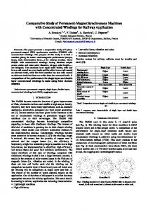
where ∆T is the temperature change from processing temperature to room temperature, ∆C is the CTE difference between matrix and reinforcement particles, and t1 , t2 and t3 are the thickness, width and length of reinforcements, respectively. With regard to the SiCp employed in this paper, it was presumed that t1 = t2 = t3 = 6.94 µm. Putting the values of these parameters into Equations (7) and (8), ∆σCTE can be described by Vp as d Vp ∆σCTE “ 85.61 (9) 1 ´ Vp Figure 11 shows the dependence of the yield strength increment on the particle volume fraction described by Equation (9), which shows that the increase in the particle volume fraction markedly enhances the yield strength increment. For the composite studied in this work, the increment in yield Materials 2016, 9, 407 13 of 16 strength ∆σCTE retains the value of 28.53 MPa.
Figure 11. 11. Dependence of of the the yield strength due to on the on reinforcement volume Figure Dependence yield strength dueCTE to mismatch CTE mismatch the reinforcement fraction. volume fraction.
From the discussions above, it is found that the direct strengthening due to the load transferring From the discussions above, it is found that the direct strengthening due to the load transferring from the matrix to the reinforcements plays the largest role in improving the yield strength. However, from the matrix to the reinforcements plays the largest role in improving the yield strength. However, the strength increase obtained from the Orowan strengthening is quite minor. This is mainly the strength increase obtained from the Orowan strengthening is quite minor. This is mainly attributed attributed to the micro size of the employed SiCp and the large inter-particle spacing [12]. Substituting to the micro size of the employed SiCp and the large inter-particle spacing [12]. Substituting the the aforementioned Equations (4), (6) and (9) into Equation (1), it follows that aforementioned Equations (4), (6) and (9) into Equation (1), it follows that d V b V + 85.61 V σ = 99 + 120.29V + 1.3738 p σ “ 99 ` 120.29Vp ` 1.3738 Vp ` 85.61 1 − V 1 ´ Vp
(10) (10)
The yield strength of the current PTF-SiCp/6061Al composite calculated through Equation (10) yield strength of the current PTF-SiC composite Equation (10) is p /6061Al is 140The MPa, which is apparently higher than the experimental datacalculated (128 MPa).through This result, as reported 140 is apparently higher than the experimental data (128 MPa). This result, as reported by by MPa, Chen which et al. [37], can be primarily attributed to the neglect of the influence of the SiCp failure Chen et al. [37], can be primarily attributed to the neglect of the influence of the SiC failure (including p (including SiCp/matrix debonding and SiCp cracking) on the composite’s yield strength. As the failed SiC /matrix debonding and SiC cracking) on the composite’s yield strength. As the failed SiCp p p SiCp cannot effectively bear load, a decrease in the yield strength will inevitably appear. Considering cannot effectively bear load, a decrease in the yield strength will inevitably appear. Considering these these factors, a modified model taking into account the SiCp failure fraction f is proposed factors, a modified model taking into account the SiCp failure fraction f is proposed d V (1 − f) (11) σ = 99 + 120.29V (1 − f) + 1.3738 b V (1 − f) + 85.61 V p1 ´ fq 1 −pV (1 − f) σ “ 99 ` 120.29Vp p1 ´ fq ` 1.3738 Vp p1 ´ fq ` 85.61 (11) 1 ´ Vp p1 ´ fq In accordance with the authors’ previous study [12], the failure fraction f attains the value of 25.6%. Substituting this intoprevious Equation (11), thethecalculated yieldf strength theofpresent In accordance with thevalue authors’ study [12], failure fraction attains thefor value 25.6%. composite isthis 132.6 MPa, which is much to the experimental datafor(128 Therefore, Substituting value into Equation (11),closer the calculated yield strength the MPa). present compositethis is modelMPa, in the form isofmuch Equation (11) capturesdata the strengthening mechanisms and discloses 132.6 which closer toaccurately the experimental (128 MPa). Therefore, this model in the including SiCp/matrix debonding and SiC p cracking the yield the significant effects of SiCp failure form of Equation (11) accurately captures the strengthening mechanisms and discloses theon significant strength of the PTF-SiCp/6061Al composite. 4. Conclusions 1.
The microstructure of the PMC-6061 alloy is composed of coarse and equiaxed α dendrites with an average size of 90.01 µm and interdendritic net-like eutectic phases, but the microstructure
Materials 2016, 9, 407
14 of 16
effects of SiCp failure including SiCp /matrix debonding and SiCp cracking on the yield strength of the PTF-SiCp /6061Al composite. 4. Conclusions 1.
2.
3.
4.
5.
6.
7.
8.
9.
The microstructure of the PMC-6061 alloy is composed of coarse and equiaxed α dendrites with an average size of 90.01 µm and interdendritic net-like eutectic phases, but the microstructure of the PTF-SiCp /6061Al composite, similar to that of the PTF-6061 alloy, consists of near-spheroidal primary particles and intergranular secondarily solidified structures except SiCp , which are distributed in the secondarily solidified structures. The primary particles of the PTF composite are more irregular and the amount of secondarily solidified structures is lower than those of the PTF alloy because of the delayed microstructural evolution rate during partial remelting. Besides, the size of the primary particles is slightly smaller than that in the PTF alloy due to the delayed microstructural evolution rate as well as the pinning effect of SiCp against the coalescence of the nearby primary particles. The amount of Mg2 Si based eutectic phases in the PTF materials is distinctly lower than that in the PMC alloy due to the dissolution of eutectic phases towards the primary α-Al particles during partial remelting. The eutectics amount in PTF composite is slightly lower than that in the PTF alloy owing to the reactions of Mg and Al with SiO2 on the surfaces of oxidized SiCp as well as the delayed microstructural evolution. The microstructures of the PTF materials are quite compact while that of the PMC alloy is porous. The porosity elimination in the PTF materials is due to the applied high pressure during solidification, the low filling velocity during mold filling, the improved feeding ability of near-spheroidal primary α-Al particles and the low liquid fraction of the semisolid slurry. The ultimate tensile strength and the yield strength of the PTF composite are 230 MPa and 128 MPa, which is apparently higher than those of the PTF (180 MPa and 99 MPa) and PMC (120 MPa and 59 MPa) alloys. The elongation of the PTF alloy attains the maximum value of 8.0% among these three materials. The superior tensile properties of the PTF alloy than the PMC alloy can be attributed to the elimination in porosities and the decrease in the average grain size as well as the lower amount of Mg2 Si phase in the former alloy. The superior tensile properties of the PTF composite over the PTF alloy should be attributed to the existence of the SiC reinforcing particles to strengthen the α-Al phase. The fracture surface of the PMC-6061 alloy is characterized by porosity features while that of the PTF-6061 alloy is quite compact. Both of the fractures belong to the intergranular mode. The fracture surface of the PTF-SiCp /6061Al composite is characterized by visible SiC particles and flat facets. The failure turns into the transgranular fracture mode. The strength increment resulted from MSL model plays largest role in improving the yield strength of the composite. However, the strength increase obtained from the Orowan strengthening is quite minor owing to the micro size of the employed SiCp and the large inter-particle spacing. A modified model taking into consideration the SiCp failure fraction was proposed to calculate the yield strength of the PTF composite. The obtained theoretical results were quite consistent with the experimental data, revealing that the SiCp failure including SiCp /matrix debonding and SiCp cracking has a significant effect on the composite’s yield strength.
Acknowledgments: The authors wish to express thanks for financial support from the Basic Scientific Fund of Gansu Universities (Grant No. G2014-07), the Program for New Century Excellent Talents in University of China (Grant No. NCET-10-0023) and the Program for Hongliu Outstanding Talents of Lanzhou University of Technology (Grant No. 2012-03).
Materials 2016, 9, 407
15 of 16
Author Contributions: Xuezheng Zhang did the experiments, data analysis and wrote the paper. Tijun Chen reviewed and revised the manuscript of this paper. He Qin; and Chong Wang contributed to the data analysis. Conflicts of Interest: The authors declare no conflict of interest.
References 1. 2. 3. 4. 5.
6. 7.
8. 9. 10.
11. 12. 13.
14.
15. 16.
17. 18. 19.
20.
Liu, Z.Y.; Xiao, B.L.; Wang, W.G.; Ma, Z.Y. Elevated temperature tensile properties and thermal expansion of CNT/2009Al composites. Compos. Sci. Technol. 2012, 72, 1826–1833. [CrossRef] Sajjadi, S.A.; Ezatpour, H.R.; Beygi, H. Microstructure and mechanical properties of Al–Al2 O3 micro and nano composites fabricated by stir casting. Mater. Sci. Eng. A 2011, 528, 8765–8771. [CrossRef] Hamedan, A.D.; Shahmiri, M. Production of A356-1 wt% SiC nanocomposite by the modified stir casting method. Mater. Sci. Eng. A 2012, 556, 921–926. [CrossRef] Lan, J.; Yang, Y.; Li, X. Microstructure and microhardness of SiC nanoparticles reinforced magnesium composites fabricated by ultrasonic method. Mater. Sci. Eng. A 2004, 386, 284–290. [CrossRef] Onat, A.; Akbulut, H.; Yilmaz, F. Production and characterisation of silicon carbide particulate reinforced aluminium–copper alloy matrix composites by direct squeeze casting method. J. Alloys Compd. 2007, 436, 375–382. [CrossRef] Hsu, C.W.; Chao, C.G. Effect of heat treatments on In-Situ Al2 O3 /TiAl3 composites produced from squeeze casting of TiO2 /A356 composites. Metall. Mater. Trans. B 2002, 33, 31–40. [CrossRef] Chao, Y.; He, F.H.; de los Reyes, M.; Long, Y.; Zhou, X.-T.; Xia, T.; Zhang, D.-L. Microstructures and Tensile Properties of Ultrafine-Grained Ni–(1–3.5) wt% SiCNP Composites Prepared by a Powder Metallurgy Route. Acta Metall. Sin. Engl. Lett. 2015, 7, 809–816. Ogel, B.; Gurbuz, R. Microstructural characterization and tensile properties of hot pressed Al–SiC composites prepared from pure Al and Cu powders. Mater. Sci. Eng. A 2001, 301, 213–220. [CrossRef] Li, P.; Chen, T.; Zhang, S.; Guan, R. Research on Semisolid Microstructural Evolution of 2024 Aluminum Alloy Prepared by Powder Thixoforming. Metals 2015, 5, 547–564. [CrossRef] Chen, Y.S.; Chen, T.J.; Zhang, S.Q.; Pu-Bo, L.I. Effects of processing parameters on microstructure and mechanical properties of powder-thixoforged 6061 aluminum alloy. Trans. Nonferrous Met. Soc. China 2015, 25, 699–712. [CrossRef] Chen, Y.S.; Chen, T.J.; Fu, W.; Li, P.B. Microstructural Evolution during Partial Remelting of 6061 Aluminum Bulk Alloy Prepared by Cold-Pressing of Alloy Powder. Adv. Mater. Res. 2013, 7, 20–24. [CrossRef] Zhang, X.Z.; Chen, T.J.; Qin, Y.H. Effects of solution treatment on tensile properties and strengthening mechanisms of SiCp/6061 Al composites fabricated by powder thixoforming. Mater. Des. 2016, 99, 182–192. Li, P.B.; Chen, T.J.; Zhang, S.Q.; Wang, Y.J. Effects of partial remelting on the microstructure evolution of SiCp/2024p aluminum composites prepared by alloy powder cold pressing. Spec. Cast. Nonferrous Alloys 2015, 35, 260–263. Chen, Y.S. The Research on Microstructure and Mechanical Properties of SiCp/6061 Al Matrix Composite Prepared by Powder Thixoforming. Master’s Thesis, Lanzhou University of Technology, Lanzhou, China, 20 April 2014. Belov, N.A.; Eskin, D.G.; Aksenov, A.A. Multicomponent Phase Diagrams: Applications for Commercial Aluminum Alloys; Elsevier: Amsterdam, The Netherlands, 2005. Cheng, F.L.; Chen, T.J.; Qi, Y.S.; Zhang, S.Q.; Yao, P. Effects of solution treatment on microstructure and mechanical properties of thixoformed Mg2 Sip /AM60B composite. J. Alloys Compd. 2015, 636, 48–60. [CrossRef] Chen, T.; Jiang, X.; Huang, H.; Ma, Y.; Li, Y.; Hao, Y. Semisolid Microstructure of AZ91D Magnesium Alloy Refined by MgCO3 . Int. J. Met. 2012, 6, 43–54. [CrossRef] Mitra, R.; Rao, V.S.C.; Maiti, R.; Chakraborty, M. Stability and response to rolling of the interfaces in cast Al–SiCp and Al–Mg alloy-SiCp composites. Mater. Sci. Eng. A 2004, 379, 391–400. [CrossRef] Zhang, S.; Chen, T.; Cheng, F.; Li, P. A Comparative Characterization of the Microstructures and Tensile Properties of As-Cast and Thixoforged in situ AM60B-10 vol% Mg2 Sip Composite and Thixoforged AM60B. Metals 2015, 5, 457–470. [CrossRef] Flemings, M.C. Solidification processing. Metall. Mater. Trans. A 1974, 5, 2121–2134. [CrossRef]
Materials 2016, 9, 407
21. 22. 23.
24. 25.
26.
27.
28.
29.
30. 31. 32. 33.
34. 35. 36. 37.
16 of 16
Fan, Z.; Fang, X.; Ji, S. Microstructure and mechanical properties of rheo-diecast (RDC) aluminium alloys. Mater. Sci. Eng. A 2005, 412, 298–306. [CrossRef] Burt, D.J. Direct thermal method: New process for development of globular alloy microstructure. Int. J. Cast. Met. Res. 2003, 16, 418–426. Tan, M.; Xin, Q.; Li, Z.; Zong, B.Y. Influence of SiC and Al2O3 particulate reinforcements and heat treatments on mechanical properties and damage evolution of Al-2618 metal matrix composites. J. Mater. Sci. 2001, 36, 2045–2053. [CrossRef] Song, M. Effects of volume fraction of SiC particles on mechanical properties of SiC/Al composites. Trans. Nonferrous Met. Soc. China 2009, 19, 1400–1404. [CrossRef] Chen, T.; Zhang, S.; Chen, Y.; Li, Y.; Ma, Y.; Hao, Y. Effects of Reheating Duration on the Microstructures and Tensile Properties of Thixoforged In Situ Mg2 Sip /AM60B Composites. Acta. Metall. Sin. 2014, 27, 957–967. [CrossRef] Gubicza, J.; Nauyoks, S.; Balogh, L.; Labar, J.; Zerda, T.W.; Ungár, T. Influence of sintering temperature and pressure on crystallite size and lattice defect structure in nanocrystalline SiC. J. Mater. Res. 2007, 22, 1314–1321. [CrossRef] Zhang, Q.; Xiao, B.L.; Wang, W.G.; Ma, Z.Y. Reactive mechanism and mechanical properties of in situ composites fabricated from an Al–TiO2 system by friction stir processing. Acta Mater. 2012, 60, 7090–7103. [CrossRef] Wang, Z.; Prashanth, K.G.; Scudino, S.; Chaubey, A.K.; Sordelet, D.J.; Zhang, W.W.; Li, Y.Y.; Eckert, J. Tensile properties of Al matrix composites reinforced with in-situ devitrified Al84Gd6Ni7Co3 glassy particles. J. Alloys Compd. 2013, 586, S419–S422. [CrossRef] Wang, Z.; Tan, J.; Sun, B.A.; Scudino, S.; Prashanth, K.G.; Zhang, W.W.; Li, Y.Y.; Eckert, J. Fabrication and mechanical properties of Al-based metal matrix composites reinforced with Mg65Cu20Zn5Y10 metallic glass particles. Mater. Sci. Eng. A 2014, 4, 53–58. [CrossRef] Poirier, D.; Drew, R.A.L.; Trudeau, M.L.; Gauvin, R. Fabrication and properties of mechanically milled alumina/aluminum nanocomposites. Mater. Sci. Eng. A 2010, 527, 7605–7614. [CrossRef] Yan, S.J.; Dai, S.L.; Zhang, X.Y.; Yang, C.; Hong, Q.H.; Chen, J.Z.; Lin, Z.M. Investigating aluminum alloy reinforced by graphene nanoflakes. Mater. Sci. Eng. A 2014, 612, 440–444. [CrossRef] Rashad, M.; Pan, F.; Tang, A.; Asif, M. Effect of Graphene Nanoplatelets addition on mechanical properties of pure aluminum using a semi-powder method. Prog. Nat. Sci. Mater. Int. 2014, 3, 101–108. [CrossRef] Tabandeh-Khorshid, M.; Ferguson, J.B.; Schultz, B.F.; Kim, C.S.; Cho, K.; Rohatgi, P.K. Strengthening mechanisms of graphene and Al2O3 reinforced aluminum nanocomposites synthesized by room temperature milling. Mater. Des. 2015, 92, 79–87. [CrossRef] Tong, X.C.; Ghosh, A.K. Fabrication of in situ TiC reinforced aluminum matrix composites. J. Mater. Sci. 2001, 36, 4059–4069. [CrossRef] Nardone, V.C.; Prewo, K.M. On the strength of discontinuous silicon carbide reinforced aluminum composites. Scr. Metall. 1986, 20, 43–48. [CrossRef] Min, S.; Xie, C.Q.; He, Y.-H. Model of effects of particle failure on yield stress of SiC reinforced aluminum alloy composites. J. Nonferrous Met. 2010, 20, 244–249. Chen, K.H.; Fang, L.; Li, X.; Huang, D.W.; Fang, H.C. Influence of particle failure on strength of SiCp/Al composite. J. Cent. South Univ. Sci. Technol. 2008, 39, 493–499. © 2016 by the authors; licensee MDPI, Basel, Switzerland. This article is an open access article distributed under the terms and conditions of the Creative Commons Attribution (CC-BY) license (http://creativecommons.org/licenses/by/4.0/).