IEEE TRANSACTIONS ON SIGNAL PROCESSING, VOL. 53, NO. 10, OCTOBER 2005
3869
A Comparison Between Uplink and Downlink MC-DS-CDMA Sensitivity to Static Timing and Clock Frequency Offsets Heidi Steendam, Herwig Bruneel, and Marc Moeneclaey
Abstract—We study the effect of fixed timing offsets and clock frequency offsets on the performance of multicarrier directsequence CDMA (MC-DS-CDMA) for both uplink and downlink communication, assuming orthogonal spreading sequences and a slowly varying multipath channel. We point out that a constant timing offset does not give rise to performance degradation for neither uplink nor downlink MC-DS-CDMA. We derive simple but accurate approximate expressions that allow us to easily quantify the effect of clock frequency offset and the influence of the different system parameters on the receiver performance in practical situations. Further, we show that for both uplink and downlink MC-DS-CDMA, the performance in the presence of a clock frequency offset rapidly degrades with an increasing number of carriers. It turns out that this degradation is larger in the uplink than in the downlink because the former suffers from a higher level of multiuser interference. For a given maximum relative clock frequency offset, enlarging the spreading factor in a fully loaded system does not affect the downlink degradation but strongly increases the uplink degradation. Index Terms—Clock frequency offset, multicarrier directsequence CDMA, synchronization.
I. INTRODUCTION
B
ECAUSE of the enormous growth of wireless services (cellular telephones, wireless local area networks, etc.) during the last decade, the need for a modulation technique that can reliably transmit high data rates at a high bandwidth efficiency arises. As multicarrier (MC) systems have good bandwidth efficiency and can offer immunity to channel dispersion, these techniques are excellent candidates for high data rate transmission over multipath channels [1]–[5]. In MC systems like orthogonal frequency-division multiplexing (OFDM), multicarrier code-division multiple access (MC-CDMA), and multicarrier direct-sequence code-division multiple access (MC-DS-CDMA), the available bandwidth is partitioned in a large number of orthogonal subchannels or carriers [1]. The (de)modulation of the (spread) data on the carriers can be accomplished by means of fast Fourier transforms (FFTs).
Manuscript received July 5, 2004; revised November 19, 2004. This work was supported by the Interuniversity Attraction Poles Program P5/11 Belgian Science Policy and was presented in part at the IEEE International Symposium on Spread Spectrum Techniques and Applications, Prague, Czech Republic, September 2002. The associate editor coordinating the review of this paper and approving it for publication was Dr. Markus Rupp. The authors are with the Telecommunications and Information Processing (TELIN) Department, Ghent University, B-9000 Gent, Belgium (e-mail:
[email protected];
[email protected];
[email protected];
[email protected]). Digital Object Identifier 10.1109/TSP.2005.855402
Further, a guard interval (cyclic prefix) is used to combat the frequency selectivity of the channel. In the OFDM technique, the data sequence to be transmitted is split into a large number of lower rate data streams, each of which modulate a different carrier of the MC system [1]–[5]. The OFDM technique is not a multiple access technique, as all carriers are modulated with data from the same user. To support multiple users, the OFDM technique must be combined with a multiple access technique. In this context, the MC modulation technique has been investigated in combination with the CDMA technique [4]–[18]. Two of these combinations are MC-CDMA and MC-DS-CDMA. In MC-CDMA [4]–[11], the original data stream is first multiplied with the spreading sequence, and then, the different chips belonging to the same data symbol are modulated on different carriers: the spreading is done in the frequency domain. In MC-DS-CDMA [6], [10]–[18], on the other hand, the serial-to-parallel converted data stream is multiplied with the spreading sequence, and then, the chips belonging to the same symbol modulate the same carrier: The spreading is done in the time-domain. Both MC-CDMA and MC-DS-CDMA have been proposed for mobile radio communications [4]–[18]. In this paper, we will focus on the MC-DS-CDMA system. The use of a large number of carriers makes multicarrier systems very sensitive to carrier and clock frequency offsets. In [19]–[24], the effect of carrier frequency offsets on various multicarrier systems has been investigated. The sensitivity to clock frequency offsets has been reported for OFDM and MC-CDMA in [19], [25]–[27] and for downlink MC-DS-CDMA in [28]. The present paper extends results from [28] by examining the effect of static clock phase offsets and clock frequency offsets on both uplink and downlink MC-DS-CDMA. In addition, we derive simple but accurate expressions for the degradation caused by the considered timing errors that allow us to easily quantify the influence of the various system parameters on this degradation. The paper is organized as follows. In Section II, we describe the uplink and downlink MC-DS-CDMA systems operating on a multipath fading channel. In Section III, we investigate the effect of constant timing offsets on uplink and downlink transmission. We derive, in Section IV, exact expressions for the performance degradation caused by clock frequency offsets in uplink and downlink MC-DS-CDMA and present simple approximations thereof. The conclusions are drawn in Section V. One of the main conclusions is that MC-DS-CDMA is much more sensitive to clock frequency offsets in the uplink than in the downlink, especially when the spreading factor is large.
1053-587X/$20.00 © 2005 IEEE
3870
IEEE TRANSACTIONS ON SIGNAL PROCESSING, VOL. 53, NO. 10, OCTOBER 2005
Fig. 1. MC-DS-CDMA transmitter structure for a single user.
II. SYSTEM DESCRIPTION A. Uplink MC-DS-CDMA The conceptual block diagram of the transmitter of an MC-DS-CDMA system for a single user is shown in Fig. 1. In MC-DS-CDMA, the complex data symbols to be transmitted are first split into symbol sequences at rate at rate . Each of these lower rate symbol sequences modulates a different carrier of the orthogonal multicarrier system. We the data symbol transmitted by user on carrier denote by during the th symbol interval; belongs to a set of carrier indices. The data symbol is then multiplied with a higher rate spreading sequence with spreading factor , where denotes the th chip of the sequence that spreads the data symbols from user during the th symbol interval. Note that the spreading sedata quence does not depend on the carrier index : All symbols from user that are transmitted during the same are spread with the same symbol interval of duration spreading sequence. It is assumed that . We denote the components of the by , i.e., spread data symbol (1) are serially transmitted on the th carThe components rier of an orthogonal multicarrier system, i.e., the spreading is done in the time-domain (see Fig. 2). (This is in contrast to MC-CDMA, where the spreading is done in the frequency dohas a duration . main.) Each component To modulate the spread data symbols on the orthogonal car-point inverse fast Fourier transform (inverse FFT) riers, an is used. To avoid the fact that the multipath channel causes interference between the data symbols at the receiver, each FFT block at the inverse FFT output is cyclically extended with a samples. This results in the sequence of samples prefix of given by (2)
Fig. 2. Time-domain spreading in MC-DS-CDMA.
The sequence is fed to a with rolloff and unit-ensquare-root raised-cosine filter , with , and ergy impulse response [which has one-sided bandwidth ] is given by (3) (see [29]), shown at the bottom of the page. The resulting conis given tinuous-time transmitted complex baseband signal by
(4) is the network reference where is a time-varying delay repreclock frequency, and senting the transmit clock phase of user . Because of the normalization factors introduced in (1) and (2), the transmitted energy per symbol on the th carrier from user is given by . In the following, it is assumed that carriers inside the roll-off area of the transmit filter are not modulated, available cari.e., they have zero amplitude. Hence, of the carriers are actually used . Asriers, only to be odd, the set of carriers actually used is given suming by . and system bandwidth The corresponding carrier spacing are given by
(5) The above approximations are valid for . In a multiuser scenario, each user transmits to the basestation . To separate the different user signals a similar signal
(3) otherwise
STEENDAM et al.: COMPARISON BETWEEN UPLINK AND DOWNLINK MC-DS-CDMA SENSITIVITY
Fig. 3.
3871
Channel structure for (a) uplink and (b) downlink.
Fig. 5. Earliest and latest possible timing to avoid interference between FFT blocks. (a) Uplink. (b) Downlink.
Fig. 4.
MC-DS-CDMA receiver structure.
at the basestation receiver, each user is assigned a unique spreading sequence , with denoting the user index. In this contribution, we consider orthogonal sequences, consisting of user-dependent Walsh–Hadamard (WH) sequences of length , multiplied with a complex-valued random scrambling sequence that is common to all active users. Hence, the maximum number of users that can be accommodated equals , i.e., the number of WH sequences of length . Note that can be chosen independently of the the number of carriers spreading factor , which in turn equals the maximum number of users. Without loss of generality, we focus on the detection . of the data symbols transmitted by the reference user transmitted by user reaches the basestation The signal through a slowly varying multipath channel. We assume that of the path gains are constant over the duration FFT blocks; the corresponding channel transfer function experienced by the th FFT block from user is denoted [see Fig. 3(a)]. We restrict our attention to wide-sense stationary uncorrelated scattering (WSSUS); hence, the second-order mois independent of both and . The ment basestation receives the sum of the resulting user signals and an . The real additive white Gaussian noise (AWGN) process are uncorrelated, and each has a and imaginary parts of . The resulting signal is applied power spectral density of to the receiver filter, which is matched to the transmit filter, and sampled at the instants (see Fig. 4). Only the samples with are kept for further processing. In uplink communication, a timing misalignment of the FFT blocks transmitted by the different users is present. However, it is assumed that this misalignment is kept within a small fraction of an FFT block by exploiting timing correction information sent by the basestation to the different users. The trans-
mitter of each user adapts its transmit clock phase by means of coarse synchronization (to be explained in more detail in Section IV) such that the samples used for further processing are not affected by interference between successive FFT , as blocks. This adaptation introduces a timing offset of the basestation. compared with the sampling instants The contribution of each user is affected by a different timing , as each user signal is generated with a difoffset ferent transmit clock and is transmitted over a different multipath channel. For each user, it is assumed that the transmitter timing is between the earliest and latest transmitter timing indisamples kept for further procated in Fig. 5(a) so that the cessing at the basestation are free from interference from neighboring blocks. This implies that the length of the cyclic prefix of must be sufficiently longer than the maximum duration the impulse responses of the composite channels with transfer . functions As the removal of the cyclic prefix at the receiver eliminates the interference between neighboring blocks, the data symbols transmitted during symbol interval are not affected by intersymbol interference from other symbol intervals. Hence, we at the omit the symbol index in the sequel. The samples output of the receiver filter are given by
(6) where is the impulse response of the composite channel , and are the filtered noise with transfer function . samples at the instants selected samples are The applied to an -point FFT followed by one-tap equalizers that scale and rotate the FFT outputs. We denote by the coefficient of the equalizer operating on the th FFT output during the th FFT block. Each equalizer output is multiplied with the
3872
IEEE TRANSACTIONS ON SIGNAL PROCESSING, VOL. 53, NO. 10, OCTOBER 2005
corresponding chip of the reference user’s spreading sequence, consecutive values are summed to yield the samples and the at the input of the decision device. Denoting by the th output of the FFT during the th FFT block and taking (2) and (6) into account, we obtain
It is instructive to consider the case where all timing offsets for . In this case, (8) are zero, i.e., and (9) reduce to (14) (15)
(7) with (8)
Hence, the contribution from user to the th FFT output is proportional to , which means that ICI is absent. does not depend on the chip index Further, as the factor , the orthogonality between the contributions from different for users to the same FFT output is not affected, i.e., ; hence, MUI is absent as well. At the input of the decision device, one obtains no timing offsets (16)
(9) The detection of the symbol able , which is given by
is based on the decision vari-
. Hence, the signal-to-noise ratio with (SNR) at the input of the decision device equals . This indicates that in the absence of timing offsets, the multipath channel affects the SNR at the input ) but does not give rise of the decision device (through to interference. B. Downlink MC-DS-CDMA
(10) where (11) and
is the additive noise contribution, with (12)
The quantity denotes the contribution from the data symbol to the sample at the input of the decision from (10) contains a useful compodevice. The sample . The quantities nent with coefficient correspond to intercarrier interference (ICI), i.e., the contribution from data symbols transmitted by the reference user on , the quantities correspond to other carriers. For multiuser interference (MUI), i.e., the contribution from data symbols transmitted by other users. We consider the case of the maximum ratio combiner (MRC). In this case, the equalizer coefficients yield (13) The MRC coefficients (13) maximize the ratio , or, equivalently, the ratio of the useful signal power to noise power at the input of the decision device.
In downlink MC-DS-CDMA, the basestation synchronizes the user signals ( for ) and broadcasts the sum of the user signals from (4) to the different users. As shown in Fig. 3(b), this broadcast signal reaches the receiver of the reference user through a slowly . The fading multipath channel with transfer function output of the channel is disturbed by AWGN with uncorrelated real and imaginary parts, each having a power spectral . The resulting signal is applied to the receiver density of filter (see Fig. 4) in order to detect the data symbols transmitted . The sampling instants are denoted to the reference user , where , and is the deviation from is the network reference clock frequency. Only the samples with indices are kept for further processing. The receiver adjusts its sampling clock phase by means of coarse synchronization (to be explained in more detail in Section IV), such that the sample is located between the earliest and corresponding to samples latest receiver timing indicated in Fig. 5(b): The to be processed are free from interference between successive blocks. This implies that the length of the cyclic prefix is sufof the composite channel ficiently longer than the duration with transfer function . As for uplink transmission, the index will be omitted in the sequel. The sample at the input of the decision device is represented by (10), which contains a useful component (ICI), multiuser interference (MUI), and noise. The quantities are given by (11), with and substituted by and , respectively. As in uplink communication, we consider the maximum ratio combiner, such that the equalizer coefficients are given by (13), with and substituted by and , respectively.
STEENDAM et al.: COMPARISON BETWEEN UPLINK AND DOWNLINK MC-DS-CDMA SENSITIVITY
3873
III. CONSTANT TIMING OFFSET A. Uplink MC-DS-CDMA In this section, we investigate the effect of constant timing on the performance of uplink MC-DSoffsets is independent of the indices and , (8) CDMA. As and (9) reduce to (17) Fig. 6. Coarse synchronization
1T > 0 .
are bandlimited: . Hence, for frequenoutside the roll-off area, the sum (18) reduces cies to one contribution, i.e., , where , is the moduloreduction of , yielding a and . result in the interval Hence, the only effect of a constant timing offset is a rotaof the contribution tion over an angle of user at the th FFT output. From (17), we observe that the for constant timing offset does not introduce ICI ( ). Further, as the quantity is independent of the chip index , the orthogonality between the contributions from the different users is not affected by the constant timing offsets, for i.e., multiuser interference is absent as well ( ). The systematic phase rotation of the FFT outputs is compensated without loss of performance by rotating the th FFT output , reover an (estimate of the) angle given by sulting in equalizer coefficients
. Hence, an increasing misalignment in time between the transmitted and the received samples is introduced. To compensate for this increasing misalignment, a coarse synchronization is performed. In uplink MC-DS-CDMA, this coarse synchronization is done at the transmitter of each user, based on timing information received from the basestation. At the transmitter of each user, the number of samples in the ) or reduced (when ) prefix is increased (when successive samples selected by the basestasuch that the tion for further processing are not affected by interference from neighboring blocks. After coarse synchronization, the resulting , timing deviation can be written as denotes the timing deviation of the first of the where samples of the considered block that are processed by the basesto an interval tation. The coarse synchronization restricts , where is the modulo reduction of , yielding a result in the interval , as shown in Fig. 6. In order to avoid interference between successive FFT blocks, we need . For carriers outside the roll-off area, (11) reduces to
(19)
(20)
(18) The composite channels
The resulting quantity at the input of the decision device is again given by (16). Hence, the effect of a constant timing offset on uplink MC-DS-CDMA is compensated without reduction of the SNR by applying the appropriate counter-rotation to each FFT output.
where (21) (22)
B. Downlink MC-DS-CDMA In the case of a constant timing offset in downlink MC-DSCDMA, the timing offset is given by . Equations (8) and substituted and (9) reduce to (17) and (18), with and , respectively. Hence, a constant timing offset by only introduces a carrier-dependent phase rotation of the FFT outputs but does not give rise to ICI or MUI. The systematic phase rotation of the FFT outputs in the downlink is compensated without reducing the SNR by applying the appropriate counter-rotation to each FFT output. IV. CLOCK FREQUENCY OFFSET A. Uplink MC-DS-CDMA Assuming that the transmitter of each user has a free-run, as ning clock with a relative clock frequency offset compared with the frequency of the basestation clock, the timing deviation increases linearly with time:
(23) (24) In (20), is given by (15). The quantity from (23) and . is the correlation between the sequences , the chips are rotated over an angle In the sequence , which depends on the chip index , corresponding the carrier index , and the timing deviation . For , to the th FFT block. Note that of user and the chips of the reference user the chips are rotated over different angles so that the orthogonality between the different user signals is destroyed: for . In the absence of clock frequency offsets, we have and , whereas in the presence of and are in general clock frequency offsets, all
3874
IEEE TRANSACTIONS ON SIGNAL PROCESSING, VOL. 53, NO. 10, OCTOBER 2005
nonzero. Hence, the clock frequency offsets give rise to both MUI and ICI. Let us consider the signal to interference plus noise ratio (SINR) at the input of the decision device related to the carrier with index . This yields SINR
(25)
where , and are contributions from the useful signal, the ICI, and the MUI, respectively:
(26) The quantity SINR from (25) still depends on the particular realization of the transfer functions and of the spreading sequences during the FFT blocks. Hence, a more conveconsidered sequence of nient performance indicator is SINR , which is obtained from (25) by replacing and by their averages and over the fading statistics and over all possible assignments of spreading sequences to the users. This and averaging involves replacing in (26) by and , respectively. We assume the application of power control so that in the absence of clock frequency offsets, all users achieve the same are seperformance: The transmitted symbol energies lected to compensate for the propagation loss differences between each user’s transmitter and the receiver at the basestation, such that the average received symbol energies take the same for all users and all carriers: . value Because of the WSSUS assumption, does not depend on the carrier index ; hence, the transmitted symbol endepends on the user index but not on the carrier ergy index . In the absence of clock frequency offsets, SINR . In the presence of clock frequency offsets, SINR is less because of the reduction of the than useful component and the introduction of ICI and MUI. We define the degradation (in decibels) caused by the clock frequency SINR . offsets as Deg Note that this degradation is a function of the carrier index . This degradation corresponds to the increase of (or ) required to maintain the BER on the th carrier in the presence of clock frequency offsets essentially the same as the BER in the absence of clock frequency offsets. In a well-designed system, this degradation should be in the order of 0.1 dB or less. A necessary condition to keep the degradation small is that the useful component on each carrier of each user is only slightly for affected by the clock frequency offsets, i.e., all carriers and all users. Hence, assuming that
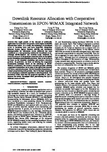
Fig. 7. Shape of jD (x)j; M = 8.
is restricted to the interval for and taking into account that the main lobe to the first zero-crossing) of width (measured from from (22) equals (see Fig. 7), we require that in order to guarantee that . is zero for integer that are not a Further, as , the condition yields multiple of for and . Now, we concentrate on , which depends on at the beginning of the FFT blocks. For the timing offsets on the small clock frequency offsets, the dependence of to index is very weak; therefore, we expect be close to its value corresponding to zero clock frequency and for offset: . Let us assume that the clock frequency is within offsets are so small that the interval for all and all . In this case, the timing offsets exhibit no jumps at the boundaries of the FFT blocks; therefore, . This yields (27) where (28) with (29) and In the following, we investigate the contributions to , assuming small clock frequency offsets. In order to represent and accurately by a truncated Taylor series (keeping up to quadratic terms) around , we need [see (21)] and [see (28)], respectively. to equals The contribution from carrier . For , one obtains from (21) and (27) (30)
STEENDAM et al.: COMPARISON BETWEEN UPLINK AND DOWNLINK MC-DS-CDMA SENSITIVITY
3875
with (31) This indicates that the contribution to the ICI is essentially pro. For given , the largest contribution portional to and . comes from the nearest carriers or , the contribution Taking increases quadratically with and becomes maximum for the carriers that are located closest to the roll-off and . area, i.e., equals The contribution from carrier of user to . For , one obtains (32) where
( 0 1) and MUI contributions ( 1) ( 0 1 1) = 64 = 5 = 57 = 32 1 = =1 = ( 0 1) 2.
Fig. 8. ICI contribution P and P k ; ;N
01
(33) for , the MUI is dominated by As , which are largest for the carthe contributions riers closest to the roll-off area. , the sum As is proportional to the square of is dominated by the MUI caused by the symbols transmitted by the nonreference users on carrier . Assuming that the clock frequency offsets of the interfering users are uni, formly distributed in the interval one obtains
(34) . The largest interference occurs when (so that a In the case where is accurate), but truncated Taylor series of is no longer valid, a trunis not accurate, and we cated Taylor series of have to use (28) instead. In this case, taking into account that is upper bounded by the right-hand side of (30). Using , the contribution from carrier of user to can now be approximated by (35)
T =T
T =T ; k
k
P
;N
N
;N
;N
;
k;
T =T
=
Again, is dominated by the sum of the contrifrom the nonreference users, and butions is given by its average over the distribution of (36) In order to illustrate the validity of the various approximations, we show in Fig. 8 the quantities , and , for and . The following curves are presented: • Exact values, based on the computation of the averages in (26), that take into account the possible jumps of the timing offset at the edges of the FFT blocks; note that , and these jumps affect , but not . These exact values correspond ; to • Approximations based on the correct expression (21) of and on the approximation (27) that ignores the possible jumps of the timing offset; • Truncated Taylor series, i.e., (30) for ICI, the minimum value resulting from (32) and (35) for MUI, and for the useful component. We observe that both the approximation [based on (21) and (27)] and the truncated Taylor series yield results that nearly coincide with the exact values that take possible jumps of the timing offset into account. This indicates that the effect of these and jumps can be safely ignored so that the quantities do not affect the performance. Moreover, the contributions , and are accurately approximated by the simple expressions resulting from the Taylor series expansion.
3876
Fig. 9.
(1
T =T
IEEE TRANSACTIONS ON SIGNAL PROCESSING, VOL. 53, NO. 10, OCTOBER 2005
)
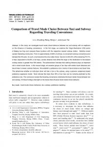
Maximum degradation in presence of clock frequency offset (N ; N =N N E =N dB).
(
+ )(
) = 10
Fig. 9 shows the maximum (over ) of the degradation of the SINR, assuming a full load and a uniform distribution in the interval of the clock frequency offof the nonreference users. We present not only the sets exact result (which considers all ICI and MUI contributions and takes into account the possible jumps of the timing offset at the edges of the FFT blocks) but the simple approximation as well, which is obtained by taking the minimum of the expressions . The accuracy of the approxi(34) and (36) for mate result indicates that the degradation in the uplink is largest (the same degradation occurs on on the carrier and is mainly caused by the noncarrier reference users’ symbols transmitted on the same carrier. For , the degradation is according to the approximation (34) and increases quadratically with and . For , the approximation (36) is valid, and the degradation is es, and (assuming sentially independent of so that ). In order to keep the degradation small (say, less than about 0.1 dB), it is required . that B. Downlink MC-DS-CDMA When the receiver of the reference user has a free-running clock with a relative clock frequency offset as compared of the basestation clock, the timing devito the frequency ation increases linearly with time: . However, in contrast with the uplink, where the increasing misalignment in time is compensated at the transmitters of the different users, the coarse synchronization in the downlink is performed at the receiver of each user. This implies that the number of samples in the prefix at the receiver is reduced ) or increased (when ), such that (when successive samples kept for further processing remain the in the region where interference from other blocks is absent. After coarse synchronization, the timing deviation is given by , where denotes the timing deviation of the first of the samples of the considered block that are processed by the receiver.
= 64
;N
= 5
;N
= 57 1 ;
T =T
= 1
T =T
=
for the carriers outside the roll-off area The quantities and substituted by are given by (20) with and , respectively, for . It folfrom (21) is independent of the user index . In lows that . The quantity the following, we use the notation from (23) is the correlation between the sequences and . However, in contrast with the uplink, is independent that of the user index . Hence, it follows from (23) with : In downlink transmission, symbols transmitted on carrier to nonreference users do not give rise to interference on the th FFT output at the receiver of the reference user. , the chips and This also can be observed in (24): For are rotated over the same angle such that the orthogonality between the different user signals on the same carrier is not af, we have and , i.e., fected. For user signals on other carriers do give rise to interference on the th carrier: The orthogonality between the user signals on different carriers is affected by the clock frequency offset. Hence, a clock frequency offset causes both intercarrier and multiuser interference. , which is transWe assume that the symbol energy mitted by the base station on carrier to user , does not depend on and . Because of the fading of the WSSUS, this yields , where denotes the symbol energy (irrespective of and ) at the input of the receiver of the reference user. As for the uplink transmission, we define SINR [see , and [see (26)] and the associated (25)], SINR , and , with and substituted by , and , respectively. Similarly as for the uplink, for small values of the clock frequency offset (i.e., without discontinuities of the timing offset at the edges of the can be approximated FFT blocks), the average and are replaced by . Note by (27), where (28) in the downlink is independent of the user index that and, therefore, will be denoted as . Taking into account for and assuming the maximum load that , we obtain (37)
STEENDAM et al.: COMPARISON BETWEEN UPLINK AND DOWNLINK MC-DS-CDMA SENSITIVITY
3877
When
, it follows from (27) that . The resulting ICI contribution is essentially the same as the right-hand side of (37) so that : The degradation is dominated by the ICI, and MUI is vir, we see from tually absent. For for . Assuming (27) that , the corresponding MUI contribution is a full load essentially the same as the right-hand side of (37): In this case, the total interference is dominated by MUI, and ICI is virtually . absent , (37) can be approximated as When
(38) Fig. 10.
Coefficients C (k ); C
(k ), and C
(k ); N
= 64; N = 57.
where (39) is given by (31). Hence, the interference power and . For given , is essentially proportional to the interference power is independent of the spreading factor. Assuming the clock frequency offset is in the interval , the interference power becomes . For given , the maximum when interference power (38) depends on the number of modulated carriers as the summation over in (38) ranges over the set of modulated carriers. An upper bound on the interference power is obtained by extending in (39) the summation interval carriers, i.e., . This corresponds over all to replacing in (38) by , which is given by
. As we observe, the approximation is close to the actual degradation. Hence, the simple expression (41) can be used to compute the degradation caused by a clock frequency offset in the downlink. To obtain small degradations, it is required , in which case, the degradation that and independent of the is proportional to spreading factor . We observe that for , the maximum degradation is much larger in the uplink than in the downlink. Whereas the ICI contributions in the uplink and the downlink are the same, the sum of the MUI contributions is much larger in the uplink than in the downlink. This can be explained by noting that the dominant MUI contributions to carrier are caused by signals transmitted on carriers in the vicinity of . •
(40)
which, for given , is independent of the number of modulated carriers. The quantity can be further simplified by using the approximation • (41) , and Fig. 10 shows the coefficients as a function of the carrier index. We observe from the behavior that the largest interference in the downlink occurs for of carriers near (but not exactly at) the the edge of the roll-off area. The coefficients and are essentially the same and become maximum for the carriers and . For carriers that are not close to the edge of the roll-off area, and are accurate approximations of , and they overestimate for the other carriers. Fig. 9 shows the maximum (over ) of the degradation of the SINR obtained with (37), along with the degradation obtained by replacing in (38) by for
In the downlink, the clock frequency offset is the same for the contributions from all user signals. Hence, the chips (24) on neighboring carriers and are rotated over nearly the same angle so that the orthogonality between the reference user and the other users is only slightly affected. For , the orthogonality is maintained so that is zero. In the uplink, the different user signals are affected by different clock frequency offsets. As a result, the chips (24) are rotated over angles that are, on average, larger than in the case of downlink transmission. Consequently, the orthogonality between the reference user and the other users is strongly affected, resulting in a MUI interference power that is substantially larger than in the downlink. In particular, the MUI contributions are the dominant ones.
In the uplink, a small degradation can be obtained only when . As compared to the downlink, this condition on is more stringent by a factor of . For , the uplink degradation is essentially proportional to ; in this region, the ratio between uplink and downlink degradation is proportional to .
3878
IEEE TRANSACTIONS ON SIGNAL PROCESSING, VOL. 53, NO. 10, OCTOBER 2005
V. CONCLUSION In this paper, we have investigated the effect of fixed timing offsets and clock frequency offsets on uplink and downlink MC-DS-CDMA with orthogonal spreading sequences on multipath fading channels. We have derived simple analytical expressions that closely approximate the performance degradation. Our conclusions can be summarized as follows. • Constant timing offsets give rise to performance degradation for neither uplink MC-DS-CDMA nor downlink MC-DS-CDMA. • Clock frequency offsets give rise to a reduction of the useful component and to the occurrence of both ICI and MUI. • For both the uplink and the downlink, the degradation caused by a clock frequency offset strongly increases with . • For given , the degradation in the downlink does not depend on the spreading factor and is es; this degrasentially proportional to dation is caused mainly by ICI. Assuming full load, the degradation in the uplink is caused mainly by MUI and increases with an increasing spreading factor. The degradation in the uplink is larger than in the downlink because the uplink is affected by a larger amount of MUI and is essentially proportional to It can be verified from [10] and [11] that the degradation for downlink MC-DS-CDMA is the same as the corresponding degradation for OFDM and essentially the same as the degradation for downlink MC-CDMA, assuming the three multicarrier systems have the same carrier spacing. REFERENCES [1] R. van Nee and R. Prasad, OFDM for Wireless Multimedia Communications. Norwell, MA: Artech House, 2000. [2] Z. Wang and G. B. Giannakis, “Wireless multicarrier communications,” IEEE Signal Process. Mag., vol. 17, no. 3, pp. 29–48, May 2000. [3] N. Morinaga, M. Nakagawa, and R. Kohno, “New concepts and technologies for achieving highly reliable and high capacity multimedia wireless communication systems,” IEEE Commun. Mag., vol. 38, no. 1, pp. 34–40, Jan. 1997. [4] L. Hanzo, M. Münster, B. J. Choi, and T. Keller, OFDM and MC-CDMA for Broadband Multi-User Communications, WLAN’s and Broadcasting. New York: Wiley, 2003. [5] S. Hara and R. Prasad, Multicarrier Techniques for 4G Mobile Communications. Norwell, MA: Artech House, 2003. , “Overview of multicarrier CDMA,” IEEE Commun. Mag., vol. 35, [6] no. 12, pp. 126–133, Dec. 1997. [7] J.-P. Linnartz, “Performance analysis of synchronous MC-CDMA in mobile Rayleigh channel with both delay and Doppler spreads,” IEEE Trans. Veh. Technol., vol. 50, no. 6, pp. 1375–1387, Nov. 2001. [8] Z. Hou and V. K. Dubey, “Exact analysis for downlink MC-CDMA in Rayleigh fading channels,” IEEE Commun. Lett., vol. 8, no. 2, pp. 90–92, Feb. 2004. [9] Q. Shi and M. Latva-Aho, “Spreading sequences for asynchronous MC-CDMA revisited: Accurate bit error rate analysis,” IEEE Trans. Commun., vol. 51, no. 1, pp. 8–11, Jan. 2003. [10] C. W. You and D. S. Hong, “Multicarrier CDMA systems using time-domain and frequency-domain spreading codes,” IEEE Trans. Commun., vol. 51, no. 1, pp. 17–21, Jan. 2003. [11] X. Gui and T. S. Ng, “Performance of asynchronous orthogonal multicarrier CDMA system in frequency selective fading channel,” IEEE Trans. Commun., vol. 47, no. 7, pp. 1084–1091, Jul. 1999.
[12] L.-L. Yang and L. Hanzo, “Multicarrier DS-CDMA: A multiple access scheme for ubiquitous broadband wireless communications,” IEEE Commun. Mag., vol. 41, no. 10, pp. 116–124, Oct. 2003. [13] S. Kondo and L. B. Milstein, “Performance of Multicarrier DS-CDMA systems,” IEEE Trans. Commun., vol. 44, no. 2, pp. 238–246, Feb. 1996. [14] L. Hanzo, L.-L. Yang, E.-L. Kuan, and K. Yen, Single and Multi-Carrier DS-CDMA: Multi-User Detection, Space-Time Spreading, Synchronization, Networking and Standards. New York: Wiley, 2003. [15] Q. Chen, E. S. Sousa, and S. Pasupathy, “Multicarrier CDMA with adaptive frequency hopping for mobile radio systems,” IEEE J. Sel. Areas Commun., vol. 14, no. 9, pp. 1852–1858, Dec. 1996. [16] L.-L. Yang and L. Hanzo, “Performance of generalized multicarrier DS-CDMA over Nakagami-m fading channels,” IEEE Trans. Commun., vol. 50, no. 6, pp. 956–966, Jun. 2002. [17] V. M. DaSilva and E. S. Sousa, “Multi-carrier orthogonal CDMA codes for quasisynchronous communication systems,” IEEE J. Sel. Areas Commun., vol. 12, no. 5, pp. 842–852, Jun. 1994. [18] E. A. Sourour and M. Nakagawa, “Performance of orthogonal multicarrier CDMA in a multipath fading channel,” IEEE Trans. Commun., vol. 44, no. 3, pp. 356–367, Mar. 1996. [19] A. M. Gallardo, M. E. Woodward, and J. Rodriguez-Tellez, “Performance of DVB-T OFDM based single frequency networks: Effects of frame synchronization, carrier frequency offset, and nonsynchronised sampling errors,” Proc. VTC Fall, pp. 962–966, Oct. 2001. [20] G. Malmgren, “Impact of carrier frequency offset, doppler spread, and time synchronization errors in OFDM based single frequency networks,” in Proc. Globecom, Nov. 1996, pp. 729–733. [21] H. Steendam and M. Moeneclaey, “The effect of carrier frequency offsets on downlink and uplink MC-DS-CDMA,” IEEE J. Sel. Areas Commun., vol. 19, no. 12, pp. 2528–2536, Dec. 2001. [22] K. Ko, T. Kim, and D. Hong, “Performance evaluation of asynchronous MC-CDMA systems with an effect of carrier-frequency offsets,” in Proceedings ICC, May 2003, pp. 3447–3451. [23] L. Tomba and W. A. Krzymien, “Sensitivity of the MC-CDMA access scheme to carrier phase noise and frequency offset,” IEEE Trans. Veh. Technol., vol. 48, no. 5, pp. 1657–1665, Sep. 1999. [24] K. Sathanantan and G. Tellambura, “Probability of error calculation of OFDM systems with frequency offset,” IEEE Trans. Commun., vol. 49, no. 11, pp. 1884–1888, Nov. 2001. [25] T. Pollet, P. Spruyt, and M. Moeneclaey, “The BER performance of OFDM systems using nonsynchronized sampling,” in Proc. Globecom, San Francisco, CA, Nov. 1994, pp. 253–257. [26] H. Steendam and M. Moeneclaey, “Sensitivity of orthogonal frequencydivision multiplexed systems to carrier and clock synchronization errors,” Signal Process., vol. 80, no. 7, pp. 1217–1229, 2000. , “The sensitivity of MC-CDMA to synchronization errors,” Eur. [27] Trans. Telecommun., Special Issue MC-SS, vol. 10, no. 4, pp. 429–436, Jul.–Aug. 1999. , “The effect of clock frequency offsets on downlink MC-DS[28] CDMA,” in Proc. IEEE Int. Symp. Spread Spectrum Techn. Applicat., Prague, Czech Republic, Sep. 2–5, 2002, pp. 113–117. [29] J. G. Proakis, Digital Communications. New York: McGraw-Hill, 2000.
Heidi Steendam received the diploma in electrical engineering and the Ph.D. degree in electrical engineering from Ghent University, Gent, Belgium, in 1995 and 2000, respectively. She is a Professor with the Department of Telecommunications and Information Processing (TELIN), Ghent University. Her main research interests are in statistical communication theory, carrier and symbol synchronization, bandwidth-efficient modulation and coding, spread-spectrum (multicarrier spread-spectrum), and satellite and mobile communication. She is the author of more than 60 scientific papers in international journals and conference proceedings. Prof. Steendam has been an executive Committee Member of the IEEE Communications and Vehicular Technology Society Joint Chapter, Benelux Section, since 2002. She has been active in various international conferences as Technical Program Committee member and Session chair.
STEENDAM et al.: COMPARISON BETWEEN UPLINK AND DOWNLINK MC-DS-CDMA SENSITIVITY
Herwig Bruneel was born in Zottegem, Belgium, in 1954. He received the M.S. degree in electrical engineering, the degree of Licentiate in computer science, and the Ph.D. degree in computer science in 1978, 1979, and 1984, respectively, all from Ghent University, Gent, Belgium. He is a Full-Time Professor with the Faculty of Applied Sciences and Head of the Department of Telecommunications and Information Processing, Ghent University, where he also leads the SMACS Research Group. His main personal research interests include stochastic modeling and analysis of communication systems, discrete-time queueing theory, and the study of ARQ protocols. He has published more than 200 papers on these subjects and is coauthor of the book, with B. G. Kim, “Discrete-Time Models for Communication Systems Including ATM” (Boston, MA: Kluwer, 1993). From October 2001 to September 2003, he served as the Academic Director for Research Affairs at Ghent University.
3879
Marc Moeneclaey received the diploma in electrical engineering and the Ph.D. degree in electrical engineering from the University of Ghent, Gent, Belgium, in 1978 and 1983, respectively. From 1978 to 1999, at Ghent University, he held various positions for the Belgian National Fund for Scientific Research (NFWO), from Research Assistant to Research Director. He is presently a Professor with the Department of Telecommunications and Information Processing (TELIN), Ghent University. His research interests include statistical communication theory, carrier and symbol synchronization, bandwidth efficient modulation and coding, spread-spectrum, and satellite and mobile communication. He is the author of more than 200 scientific papers in international journals and conference proceedings. Together with Prof. H. Meyr (RWTH Aachen) and Dr. S. Fechtel (Siemens AG), he co-authored the book Digital Communication Receivers—Synchronization, Channel Estimation, and Signal Processing (New York: Wiley, 1998). Dr. Moeneclaey served as Editor for Synchronization and for the IEEE TRANSACTIONS ON COMMUNICATIONS from 1992 to 1994. He was co-guest editor for the December 2001 IEEE Special Issue on Signal Synchronization in Digital Transmission Systems of the IEEE JOURNAL OF SELECTED AREAS IN COMMUNICATIONS. From 1993 to 2002, he has been an executive Committee Member of the IEEE Communications and Vehicular Technology Society Joint Chapter, Benelux Section. He has been active in various international conferences as Technical Program Committee member and Session chairman.