microwave thermal rocket was independently proposed by Parkin in 2003 [3] as an adaptation of nuclear .... Multistage collectors offer further improvements but ...
A Comparison of Laser and Microwave Approaches to CW Beamed Energy Launch Jordin T. Kare† and Kevin L. G. Parkin‡ ‡
† Kare Technical Consulting, 908 15th Ave. East Seattle WA 98112, USA Division of Engineering and Applied Science, California Institute of Technology, 1200 East California Boulevard, Pasadena, CA 91125, USA
Abstract. One approach to beamed energy propulsion uses a solid heat exchanger to absorb energy from a distant source and transfer it to a working fluid. Systems of this type can be designed using either microwave or laser sources. In general, microwave sources have been expected to be less expensive than lasers for a given power, but to be more limited in range and/or energy density. With the development of high power millimeter-wave sources and low-cost diode laser arrays, both assumptions are open to question. In this paper, we compare current and projected microwave and laser source technologies for a 100-kilogram-class ground-to-orbit launch system and identify key issues affecting the system-level trade between the two approaches.
HEAT-EXCHANGER LAUNCH CONCEPTS The laser-driven Heat Exchanger (HX) approach to ground-to-orbit laser launch was proposed by Kare in 1993 [1] as an alternative to pulsed ablative propulsion, primarily as way to continue laser launch development with continuous-wave (CW) lasers after the end of large-scale development of high-average-power pulsed lasers. [ 2 ] The microwave thermal rocket was independently proposed by Parkin in 2003 [3] as an adaptation of nuclear thermal propulsion to an external ground-based microwave energy source rather than an on-board nuclear reactor. Both Kare and Parkin offered conceptual designs for a system capable of launching 100 kg payloads to low Earth orbit. The two designs differ radically, as shown in Table 1, effectively illustrating the wide design space available with heat-exchanger propulsion. Nevertheless, either system could be implemented with only minor changes using either a laser or microwave source. This suggests that we can compare laser and microwave-based systems without considering the details of the vehicle design. This paper compares the two systems from the standpoint of the technical maturity, efficiency, and capital cost of the beam source – from power plant through laser or microwave generator to transmitting optics or antennas. The reference laser source considered is described by Kare in [4]. It consists of a few thousand independent beam modules, each of which produces 50 kW of beam power at 1.08 µm. Each beam module consists of six 10-kW diode-pumped fiber lasers feeding a single 1-meter-class telescope with its own pointing and tracking system. Beam modules are preferred over a single large laser and beam director due to their much lower development cost and ability to leverage industrial and military laser development.
CP830, Beamed Energy Propulsion: Fourth International Symposium, edited by K. Komurasaki, T. Yabe, S. Uchida, and A. Sasoh
© 2006 American Institute of Physics 0-7354-0322-8/06/$23.00 388 Downloaded 30 May 2006 to 131.215.240.9. Redistribution subject to AIP license or copyright, see http://proceedings.aip.org/proceedings/cpcr.jsp
TABLE 1. Approximate parameters of proposed launch system concepts Laser (Kare) Microwave (Parkin) Design vacuum Isp 600 seconds 800-1000 seconds Heat exchanger material Metallic Ni Silicon Carbide Heat exchanger type Laminar flow Turbulent flow Operating temperature 1000 C 2500 C Operating flux 5 MW/m2 30 MW/m2 Propellant feed system Pressure fed Pump fed Vehicle type Expendable Reusable Power at vehicle 100 MW 300 MW Powered trajectory length 600-800 km 200 km Powered flight time 400 s 200 s Design payload to orbit 100 kg 100 kg
The microwave source is a phased array of several hundred closely-spaced parabolic dish antennas, each fed by a single 1 MW-class gyrotron oscillator operating at 140 GHz (2.1 mm wavelength). The antennas are mechanically steered to track the vehicle, with fine pointing done electronically via phase control over the array. This design is derived from a 30 MW, 245 GHz, ground-based beam facility proposed and analyzed by Myrabo, Benford, and Dickinson [5,6], with the frequency chosen to correspond to the shortest-wavelength commercially available gyrotrons. An optimization among atmospheric transmission, array size, and possible future gyrotron technology has yet to be attempted.
TECHNOLOGY READINESS Laser Fiber lasers up to 1 kW power are in commercial production; using the NASA Technology Readiness Level (TRL) scale [7], they are TRL 8 (TRL 9 being reserved for technology that has actually been used in a launcher or similar field application). MultikW single-fiber lasers are regarded by the laser community as feasible [8]; alternatively, fiber lasers appear to be well-suited to phase-locking or wavelength-combining techniques that would provide the radiance (power per unit area per unit solid angle) of a multi-kW laser without further increases in single-fiber power. We assign a TRL of 3 (“Analytical and experimental critical function and/or characteristic proof of concept”) to 10-kW fiber laser sources, but expect that multi-kilowatt fiber lasers will be developed independently of any laser launch project, because of their wide potential applications. Lower power lasers could be used for a launcher, although each laser requires a diffraction-limited minimum aperture, so the total telescope area is inversely proportional to the unit laser power. However, existing lasers would require considerable redesign to reduce costs to a practical level for a launch system, so they can only be considered breadboard versions (TRL 5) of launch system hardware.
389 Downloaded 30 May 2006 to 131.215.240.9. Redistribution subject to AIP license or copyright, see http://proceedings.aip.org/proceedings/cpcr.jsp
Other suitable laser technologies for the modular laser source are also at TRL 3, including Diode Pumped Alkali-vapor Lasers (DPALs) [9] and noncoherent laser diode arrays with spectral beam combining [10].
Microwave Source Individual 900 kW continuous wave (CW) gyrotrons at 110 GHz and 140 GHz are TRL 8: in commercial production, with further development being driven by their application to electron cyclotron-resonance heating (ECH) systems for magneticconfinement fusion experiments such as DIII-D [11]. In principle, any number of gyrotron oscillators can be phase-locked to produce a common frequency. Phase locking of microwave oscillators has been used since the 1940s and has reached powers exceeding 1 GW [12]. Phase locking of gyrotron oscillators has been analyzed [13], but it has been demonstrated only at low power and with small numbers of oscillators [14]. Hence, phase locking of gyrotrons is at TRL 3-4. We estimate that developing the hardware for a large phase-locked 140 GHz gyrotron array will require a development effort comparable to that for 10-kW-class fiber lasers. The technical risk of such an effort is probably low compared to laser development, but the cost may be high because several high-power gyrotrons are needed for realistic tests. A master oscillator - power amplifier (MOPA) configuration avoids the phase stability issues of large phase-locked oscillator arrays. However, CW gyrotron amplifiers above 100 GHz are substantially less developed than power oscillators, placing them also at TRL 4. A near term TRL 5-6 option is to use larger numbers of less powerful gyro-klystron amplifiers developed for W-band (94 GHz) radar applications, but the cost of such a system is unknown.
Apertures and Array The laser system’s optical telescope/beam director technology is TRL 8 – existing high-power laser systems such as the Tactical High Energy Laser use essentially similar beam directors at comparable power levels. The baseline launch system is sized specifically to avoid the need to correct for atmospheric turbulence, so adaptive optics technologies are not needed, and each beam module operates independently, so no special techniques are needed for an array of modules. The specific hardware used for launch system beam modules will be new, however, so the beam director is TRL 5. Millimeter-wave steerable dish antennas have such an extensive field history that they can reasonably be classed as TRL 9. Receive-only millimeter-wave phased arrays of steerable dishes have been demonstrated in radioastronomy. High power phased arrays with electronic steering and tracking are used in military radars. Feed systems (except for rotary joints) are comparable to fusion experiment ECH feed systems. However, a launch system array would be unprecedented in size and average power, and in the combination of number of apertures, precision, and tracking requirements. In particular, no suitable real-time phase measurement and correction system has been demonstrated or, to our knowledge, designed. Consequently, we place the phase control system, and thus the phased array as a whole, at TRL 2-3. Table 2 summarizes the technology readiness levels for the two systems.
390 Downloaded 30 May 2006 to 131.215.240.9. Redistribution subject to AIP license or copyright, see http://proceedings.aip.org/proceedings/cpcr.jsp
TABLE 2. Estimated Technology Readiness Levels Laser Microwave Laser Gyrotron 1 kW 4-6 Single 1 MW 10 kW 3 Phase locked array Gyroklystron MOPA Overall source 3 Beam director Antenna array Telescope 8-9 mm-wave dish Fore optics 6 Feed Fiber feed 4 Phase control Pointing/tracking 5 Integrated system Overall aperture 4 Overall system 3
8 3 5 3 9 5 2-3 2-3 2-3 2-3
EFFICIENCY Source Efficiency Nominal efficiencies and likely ranges of efficiency for laser and microwave sources are given in Table 3. The laser diode efficiency is a compromise between the 50–55% efficiencies of current production diode arrays at 25 C, and efficiencies of 70-75% that have been demonstrated in single diodes [15]. A further few-percent gain in efficiency is possible by operating diode arrays at 10 C. For CW gyrotrons at 110 GHz, the advent of single depressed collectors in the mid 1990s raised practical gyrotron DC efficiency from 30% to 50%, with a 62% theoretical limit [16]. In practice, the current state of the art allows routine operation at 40% efficiency, with 50% as a goal for near-future systems. Multistage collectors offer further improvements but are as yet are untried. Gyrotrons have a small advantage in DC power supply efficiency because they operate at high voltage; ohmic losses and semiconductor voltage drops are more significant in low-voltage, high-current diode laser supplies. TABLE 3. Laser and gyrotron efficiency Laser diodes (DC-diode light) Fiber conversion (diode light – fiber light) Laser DC efficiency Power supply Laser wallplug efficiency Gyrotrons (depressed collector) Power supply Gyrotron wallplug efficiency
Nominal 65% 80% 52% 95% 49%
Range 55-75% 70-90% 39-69% 90-95% 35-64%
50% 97% 49%
40-55% 95-99% 38-54%
391 Downloaded 30 May 2006 to 131.215.240.9. Redistribution subject to AIP license or copyright, see http://proceedings.aip.org/proceedings/cpcr.jsp
Aperture Efficiency The aperture efficiency ηap accounts for power lost between the laser or gyrotron output and free space, due to absorption, scattering, spillover (energy lost around the edges of optics), and blockage or diffraction by secondary reflectors and struts. For the laser system, ηap will be in the range of 0.8 to 0.9, assuming all optics including the primary mirror are multilayer coated for high reflectance. Our nominal value is ηap = 0.83, i.e., 50 kW module output power from 60 kW of laser power. The losses for a single microwave aperture will probably be in the same range, although in the absence of a specific antenna and feed design the uncertainties are larger. The ECH system on the D-IIID fusion experiment has waveguide losses of 2%/40 m and 0.6% per dihedral (sharp) bend [17], so waveguide losses from the gyrotron to the antenna feed can be as small as a few percent, provided the gyrotron is adjacent to the antenna. We take the same nominal value of ηap = 0.83, with the caveat that system trades – for example, locating the gyrotrons in a common building outside the antenna array – could lower the efficiency 10% or more.
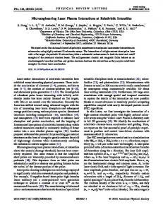
Array Efficiency To a first approximation, if individual antennas are uniformly illuminated and in perfect phase, a phased array of dish antennas has an efficiency ηarray equal to f fill , the fraction of the array area filled by antenna surface. The lost energy is radiated into sidelobes of the desired main beam. A close-packed hexagonal array of circular dishes has f fill = π /(2 3) ≈ 0.907. Practical issues, such as ensuring dishes do not collide if there is a drive or control failure, may reduce f fill considerably. If the array is mechanically steered away from zenith by an angle θz (except by tilting the entire array as a unit) the projected spacing 1.0 between antennas in the d/s0 = 1.0 0.9 direction of the steering will 0.9 be s = s0 cos(θ z ) . This will 0.8 initially increase efficiency 0.8 as the apparent gaps between 0.7 0.7 antennas are reduced, then 0.6 decrease efficiency as 0.6 antenna beams are blocked 0.5 by neighboring antennas. 0.5 0 10 20 30 40 50 60 Approximating a row of circular dishes as a simple Maximum zenith angle, deg. rectangular strip of width d, FIGURE 1. Efficiency of a phased array of steerable dishes, the angle-dependent array averaged over zenith angle, due to fill factor (sidelobe) losses efficiency is and mutual blockage. d is the row width (~dish diameter); s0 is η ( θ ) = d /( s cos( θ )) for z 0 z the row spacing. cos(θ z ) ≥ d / s0 , and
392 Downloaded 30 May 2006 to 131.215.240.9. Redistribution subject to AIP license or copyright, see http://proceedings.aip.org/proceedings/cpcr.jsp
s0 cos(θ z ) / d for cos(θ z ) < d / s0 . Figure 1 shows the result of using this simple model and averaging the losses over angle from θ z = 0 to a given maximum angle (a rough approximation to averaging over a vehicle trajectory). * Amplitude variations or phase errors between dishes, and pointing errors or nonuniform illumination of individual dishes, also lower the array efficiency. For 2
example, for random phase errors of rms magnitude σ, the efficiency is e−(2 πσ / λ ) ; σ = 0.036 λ (a 13° phase error or a path length error of ~80 µm), corresponds to 95% efficiency. We take nominal array efficiency of 0.9 (static fill factor) x 0.9 (trajectory-averaged fill factor/blockage) x 0.95 (amplitude/phase errors) = 0.77, but note that the efficiency for a real array could easily be lower.
Atmospheric Absorption and Scattering At 1.08 µm, loss in the atmosphere is dominated by particulate scattering, which varies widely from site to site. Cook [18] calculates the overall transmission for YAG lasers (1.06 µm) vertically from sea level to 150 km as 0.73 for year-round average conditions in the Sea of Japan, but notes that the transmission from 3 km altitude would be greater than 0.9. We assume a land site can be found with vertical transmission of 0.85 or better under most clear-sky conditions. Microwave losses at the wavelengths of interest are dominated by water vapor absorption. Water vapor has an atmospheric scale height of 1-2 km, and site surveys for infrared and millimeter wave astronomy projects have identified several mountaintop sites within the continental United States with low precipitable water vapor (PWV). High peaks unfortunately tend to have issues of site accessibility, environmental and public use considerations, and weather availability, but as with the laser system we assume a usable site can be found with a PWV of 7 mm or less, corresponding to ~85% vertical transmission at 140 GHz, most of the time. Atmospheric losses increase exponentially with path length through the atmosphere, but for zenith angles less than 60° and 85% zenith transmission, the trajectory-averaged losses (as opposed to the worst-case losses) will be larger than the zenith losses by a factor of only 1.2 – 1.5. For system comparisons and costing we assume a trajectoryaverage transmission ηatm = 0.8 for both systems. Neither laser nor 140 GHz radiation will penetrate visible clouds, fog, or precipitation without large losses, so neither system has a large advantage with respect to weather-related availability.
APERTURE SIZE, BEAM DIVERGENCE, AND SCALING The most difficult aspect of comparing microwave and laser systems relates to the scaling of the systems with power and beam divergence. Even for nominally equal *
Mutual blockage will be a more severe problem if vehicles are to be launched from the ground with beamed power, i.e., without a booster stage, since that will require the array to point nearly to the horizon in at least one direction.
393 Downloaded 30 May 2006 to 131.215.240.9. Redistribution subject to AIP license or copyright, see http://proceedings.aip.org/proceedings/cpcr.jsp
beam divergence, the two systems will have different beam profiles, zenith-angle dependence, and beam shapes, and thus different losses as a function of range and zenith angle. To permit a preliminary comparison, we take the laser system as a reference. The baseline system is designed to produce a circular Gaussian beam with an effective angular width θ beam (full width to 1/e2 flux, 87% encircled energy) of 16 µrad at θ z = 60°. The beam width is the result of convolving several effects (diffraction of the Gaussian initial beams, atmospheric turbulence, jitter, and module-to-module pointing errors) and is thus relatively insensitive to any particular change in the system design. A nominally equivalent microwave system with a uniformly-illuminated circular phased array of diameter D would have an elliptical beam (due to the foreshortening of the array as seen from off-zenith) with an Airy profile. The angular divergence to the first zero (83% en-ellipsed energy) would be 2.44 λ / D (minor axis) by 2.44 λ / D cos(θ z ) (major axis). Defining the geometric mean of these to be the microwave system’s θ beam :
θbeam 2 = (2.44 λ / D) 2 cos(θ z ), or D = (2.44 λ /θbeam )
cos(θ z )
(1)
The array diameter for 16 µrad divergence at 140 GHz and θ z = 60° is 462 meters, which is uncomfortably large: the array area is 168,000 m2. However, the microwave system can trade power for aperture, by having the vehicle fly a shorter, higheracceleration trajectory.* This trade is not wholly independent of the vehicle and system design; for example, the vehicle propulsion system mass will tend to increase with beam power, and the effects of gravity on the trajectory will be reduced. For a first-order estimate, however, we assume that by adjusting the heat exchanger size and other system parameters, we can maintain a constant payload for a constant product Pbeam D .
SYSTEM COST A full launch system cost estimate is well beyond the scope of this paper, but a rough estimate of the capital costs is possible. We consider only the cost of the source, transmitting aperture, and prime power, assuming the launcher has a dedicated power plant. The capital cost of the system is given by Csys = c s Psα + c ps
Ps β
ηs
+ c prime
Ps
ηs η ps
+ Cap N ap γ
(2)
where cs c ps
= Source (laser or gyrotron) cost per output watt = DC power supply cost per DC watt
*
The laser system can do this also, but the baseline laser system cost is already dominated by the laser cost, so reducing aperture area and cost is not useful. The laser system would benefit from a trade in the opposite direction, toward longer range and lower power, but θbeam is limited by atmospheric turbulence and cannot be much reduced without using adaptive optics. Minimum acceleration is also limited by Earth’s gravity, and maximum trajectory length by Earth’s curvature, and the laser system is near these limits as well.
394 Downloaded 30 May 2006 to 131.215.240.9. Redistribution subject to AIP license or copyright, see http://proceedings.aip.org/proceedings/cpcr.jsp
c prime = Prime power (generator) cost per watt Cap = Unit aperture (dish or beam projector) cost Ps = Total source power in watts ηs , η ps = Source, DC power supply, efficiency N ap = Number of apertures α, β , γ = Scaling exponents for costs The cost scaling exponents account for the learning curve – the decrease in unit cost of hardware with increasing production. This is often expressed as a learning curve factor f (cost reduction for each doubling of the number of units); for cost-scaling exponent x, x = 1+ ln(1− f ) /ln(2) , e.g., a 10% learning curve corresponds to an exponent of 0.85 For the laser system, we assume α = 0.76 (a 15% learning curve, typical for unique complex assemblies) for laser cost scaling. As a reference point, we estimate a cost of $100/watt, or $1M per unit, for a hypothetical 10 kW fiber laser, quantity one. Current sub-1-kW fiber lasers are more expensive ($200 – 500/watt) but use single tele– communications-type laser diodes ($75-150/watt) as pumps, while higher power fiber lasers will use diode laser bars, currently about $30/watt in single quantity [19]. This gives a predicted cost of $10.50/watt for 15,000 lasers ( Ps = 150 MW). That figure includes the cost of DC power supplies, which are commodity products with modest learning curves (95%) but are cheap, nominally $0.35/DC watt in 10,000 unit quantities. $10.50/watt is consistent with a previous estimate of $6 – 10/watt for fiber lasers by one of us (Kare [20]) based on the projected cost of diode laser arrays. The cost of telescopes varies widely depending on requirements; a single researchquality 1-m astronomical telescope can cost $0.5 – 1 M, and a fast-slewing beam director much more. The launch system beam projector has looser requirements on the optics and mount than a typical astronomical telescope, but adds high power and a pointing and tracking subsystem. Using a single-unit cost of $750K and a cost exponent γ of 0.85 (10% scaling factor), the unit cost for 2500 beam projectors would be $228K. The cost for prime power depends on how heavily the launch system is used. A launch system will require several hundred megawatts of electricity, with intermittent loading. If the system is lightly used (a few launches per day) an energy storage system (batteries, flywheels, etc.) might be acceptable, recharged from the national grid or a small generator. However, for heavier use, or bursts of several successive launches, a dedicated power source will be needed. We assume a dedicated gas-turbine power plant, with an installed cost of approximately $0.60/watt. We do not yet have a good estimate for cooling system costs, and they are likely to be site-dependent. For this paper we assume cooling costs are small compared to generator costs, particularly since only about half of the prime power becomes waste heat. Thus we lump cooling costs into c prime , along with costs for power and cooling water distribution, and assume c prime = $0.80/watt, with no learning curve discount, for both systems. Large gyrotrons currently cost about $1/watt for 2-10 units. A 15% learning curve (α = 0.76) gives a gyrotron cost of ~$0.40/watt for 200 units. Power supplies for a 1MW
395 Downloaded 30 May 2006 to 131.215.240.9. Redistribution subject to AIP license or copyright, see http://proceedings.aip.org/proceedings/cpcr.jsp
gyrotron cost about $1/RF watt ($0.50/DC watt at ηs ≈ 0.5 ) but support hardware (superconducting magnet, stand, connectors, control electronics) and waveguide feeds raise the total cost for an installed gyrotron source to about $4/RF watt. Gyrotron power supplies and support hardware are specialized, but less so than the gyrotrons themselves, so we assume those costs scale with a 90% learning curve (β = 0.85). This gives a source cost of roughly $2.20/watt for 200 gyrotrons, or $1.80/watt for 600. This is consistent with estimates from experts in the field [21]. As another point of comparison, the International Thermonuclear Experimental Reactor (ITER) ECH system, with 27 1 MW gyrotrons (24 at 170 GHz, 3 at 120 GHz) has a projected cost of $82.5 million, almost exactly $3/watt. [22] This includes $26.3 million for power supplies, $14.5 million for RF sources (gyrotrons) and controls, and $41.7 million for transmission lines (waveguides); launcher hardware would have a higher duty cycle and add phase locking requirements, but have less waveguide complexity. Microwave antenna cost can be estimated by analogy to astronomical arrays, specifically the Atacama Large Millimeter Array (ALMA) [23]. ALMA will have 64 12-meter mm-wave antennas, with a projected cost of approximately $3.3M each, including mounts, which is $29.5K/m2 (FY2000 dollars) [24]. The ALMA array has a maximum operating frequency of 790 GHz, but has tolerances similar to those for a 140 GHz launch array because power beaming requires very low losses. In particular, ALMA has specified a 25 µm rms surface roughness, which would produce a 2.1% scattering loss at 140 GHz but nearly 3 dB (50%) loss at 790 GHz. Launch array antennas must also handle high power and provide full performance while slewing, and we include the as-yet-undetermined cost of the phase control system in the antenna cost. We therefore assume 12-meter power beaming antennas would cost 1/3 more than ALMA antennas ($4.45M or $40K/m2) at quantity 64, with a 10% learning curve (γ = 0.85). Scaling of antenna cost with antenna diameter d is unclear; assuming Cap ∝ dδ we 4.0 Dish cost scales as
3.5
d^2 d^2.5
3.0 System
2.5 2.0
Laser system
1.5
Laser source
Antenna array - dishes - mounts - phase control
1.0 Microwave source - gyrotrons - power supplies - power & cooling
0.5 0.0 15
20
25
30
35
40
45
50
Nominal beam divergence, µradians
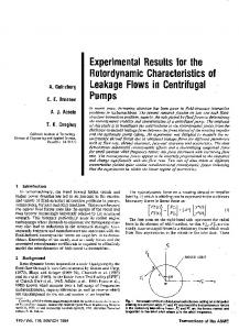
FIGURE 2. Microwave system cost vs. beam divergence (∝ 1/array diameter)
396 Downloaded 30 May 2006 to 131.215.240.9. Redistribution subject to AIP license or copyright, see http://proceedings.aip.org/proceedings/cpcr.jsp
have found examples and estimates ranging from δ = 1.5 [25] to δ = 2.7 . ( δ = 2.0 is a constant cost per square meter). Figure 2 shows the scaling of the aperture cost and source cost (including prime power) for the microwave system as a function of the beam divergence, for δ = 2.0 and 2.5. Both the number and size of the antennas vary enter into the calculation, so the total array cost varies as D3δ / 2−γ or, equivalently, as φ beamγ − 3δ / 2 . Finally, Table 4 summarizes the cost estimates and relative costs for the two systems, assuming an approximately optimum trade between array size and source power for the microwave system. TABLE 4. 100-kg launch system beam source cost comparison Laser Microwave Average power at vehicle, MW 100 250 Average atmospheric transmission 0.8 0.8 Power in beam, MW 125 312.5 Array efficiency 1 0.77 Transmitted power, MW 125 406 Aperture efficiency 0.83 0.83 Source power, MW 150 487
Ratio 2.5 1 2.5 0.77 3.25 1 3.25
laser/gyrotron cost, $/W Power supply and support cost, $/W* Prime power and cooling cost, $/W* Source cost, $/W Source cost, $M
9.80 0.70 1.60 12.10 1,815
0.036 2.19 1 0.29 0.94
# apertures Aperture diameter, m Aperture cost, $/m2 ** Unit aperture cost, $K Array cost, $M
2500 1 n/a 228 570
0.36 1.54 1.60 3.49 1,702 487 7.5 22.8 994 484
n/a n/a n/a n/a 0.85
System cost, $M 2,385 2,187 0.92 *cost per RF or laser watt; source efficiency included **assumes δ = 2.5
DISCUSSION Although the cost per watt of bare gyrotrons is estimated to be under 4% the cost of fiber lasers, gyrotrons have less than a 3:1 cost advantage per watt reaching the vehicle once the full source cost and efficiency are considered. This remaining advantage is negated at this scale by the high cost of the microwave antenna array. Trading array size for microwave power leads to a microwave system with roughly 3 times the power at the vehicle as in the laser system – essentially the same ratio as that between the original Kare and Parkin conceptual system designs. The costs of the two systems then differ by much less than the probable errors in our estimates.
397 Downloaded 30 May 2006 to 131.215.240.9. Redistribution subject to AIP license or copyright, see http://proceedings.aip.org/proceedings/cpcr.jsp
The microwave system has a much shorter range and acceleration time than the laser system. This implies higher accelerations and higher loads on the vehicle and payload, but also means the microwave system can launch more payloads in a short period of time, or more total mass over a long period. Both systems have enormous total launch capacity compared to current launchers, so capital cost and payload size are probably more important than launch rate in the near term, but launch rate may be significant for some users. With the system parameters used here, the microwave system scales favorably to larger payloads and higher powers, since a simple scaling of the system increases power and reduces beam divergence (increasing the useful range) while the laser system beam divergence does not improve with power. Conversely, the microwave system scales down poorly, either for smaller systems or for development and flight demonstrations.
CONCLUSIONS Microwave- and laser-based beamed energy launchers both have technical unknowns that place them at TRL 2 to 3. For modular laser sources, there is a single major technical issue – scaling unit laser power to ~10 kW or greater. For microwave systems, the clearest technical issue is phase locking of large gyrotron arrays, but the microwave phased array aperture, and specifically phase sensing and control on the required scale, are also major challenges. Laser systems have a modest advantage in end-to-end efficiency, mainly due to difficult-to-eliminate array losses in a steerable-dish phased array. Other losses need further analysis, but appear to be similar for the two systems. The laser system cost is, not surprisingly, dominated by the lasers themselves; the laser system will be competitive if and only if laser costs fall at least roughly as projected. For the microwave system, there is no dominant cost element likely to be affected by technical progress or production scaling, but the greatest gains in system performance vs. cost would come from lowering the cost of large millimeter-wave antennas.
ACKNOWLEDGMENTS The authors would like to thank Dr. James N. Benford of Microwave Sciences Inc. for his advice, particularly on HPM sources and phased arrays.
REFERENCES 1. 2.
3.
J. T. Kare, “Laser-Powered Heat-Exchanger Rocket for Ground-to-Orbit Launch” Journal of Propulsion and Power 11(3) 535-543 (1995). J. T. Kare, “Laser Launch -- The Second Wave,” in Beamed Energy Propulsion, Proc. 1st Internat. Symp. on Beamed Energy Propulsion, ed. by A. V. Pakhomov, AIP Conf. Proceedings 664, Melville, New York, 2003, pp. 22-36. K. L. G. Parkin and F. E. C. Culick, Feasibility and Performance of the Microwave Thermal Rocket Launcher, Proc. Second Internat. Symp. on Beamed Energy Propulsion, ed. by K. Komurasaki, AIP Conf. Proceedings 702, Melville, New York, 2004, pp. 418-429.
398 Downloaded 30 May 2006 to 131.215.240.9. Redistribution subject to AIP license or copyright, see http://proceedings.aip.org/proceedings/cpcr.jsp
4.
5.
6.
7. 8.
9. 10.
11.
12.
13.
14. 15. 16. 17.
18. 19.
20.
21. 22.
23. 24. 25.
26. 27.
K. L. G. Parkin and F. E. C. Culick, Feasibility and Performance of the Microwave Thermal Rocket Launcher, Proc. Second Internat. Symp. on Beamed Energy Propulsion, ed. by K. Komurasaki, AIP Conf. Proceedings 702, Melville, New York, 2004, pp. 418-429. K. L. G. Parkin and F. E. C. Culick, Feasibility and Performance of the Microwave Thermal Rocket Launcher, Proc. Second Internat. Symp. on Beamed Energy Propulsion, ed. by K. Komurasaki, AIP Conf. Proceedings 702, Melville, New York, 2004, pp. 418-429. J. T. Kare, “Modular Laser Options for HX Laser Launch” in Beamed Energy Propulsion, Proc. 3rd Internat. Symp. on Beamed Energy Propulsion, ed. by A. V. Pakhomov and L. N. Myrabo, AIP Conf. Proceedings 766, Melville, New York, 2005, pp. 128-139. L. N. Myrabo and J. Benford, “Propulsion of Small Launch Vehicles Using High Power Millimeter Waves” in Intense Microwave Pulses II, ed. by H. E. Brandt, SPIE Proceedings 2154, Bellingham, WA, 1994, pp. 198-217. J. Benford, and R. Dickinson, “Space Propulsion and Power Beaming Using Millimeter Systems” in Intense Microwave Pulses III, ed. by H.E. Brandt, SPIE Proceedings 2557, Bellingham, WA, 1995, pp. 179-192. Also published in Space Energy and Transportation 1, p. 211 (1995). J. C. Mankins, “Technology Readiness Levels: A White Paper,” NASA, Office of Space Access and Technology, Advanced Concepts Office, 6 April 1995. J. Nilsson, J. K. Sahu, Y. Jeong, W. A. Clarkson, R. Selvas, A. B. Grudinin and S. Alam, “High Power Fiber Lasers: New Developments” in Advances in Fiber Devices, ed. by L. N. Durvasula, SPIE Proceedings 4974, Bellingham, WA, 2003, pp. 50-59. W. F. Krupke, R. J.Beach, V. Kanz, and S. A. Payne, “DPAL: a new class of CW near-infrared high-power diode-pumped alkali (vapor) lasers” in Gas and Chemical Lasers, and Applications III, ed. by S. J. Davis and M. C. Heaven, SPIE Proceedings 5334, Bellingham, WA, 2004, pp. 156-167. C. Hamilton, S. Tidwell, J. S. Meekhof, G. Gitkind,, and D. Lowenthal, “High power laser source with spectrally beam combined diode laser bars” in High-Power Diode Laser Technology and Applications II, ed. by M. S. Zediker, SPIE Proceedings 5336, Bellingham, WA, 2004, pp. 1-10. J. Lohr et al., “High power long pulse performance of the DIII–D gyrotron installation” in Proc. 12th Joint Workshop on Electron Cyclotron Emission and Electron Cyclotron Resonance Heating, ed. by G. Giruzzi, World Scientific, Singapore, 2003. See also . J. Benford, J. Levine, N. Aiello, and B. Harteneck, “Design and Operation of a Module of Phase-Locked Relativistic Magnetrons,” J. Appl. Phys 70, 2838 (1991). A. W. Fliflet and W. M. Manheimer, “Nonlinear theory of phase locking gyrotron oscillators driven by an external signal,” Phys. Rev. A 39, 3432–3443 (1989). H.H.Guo et al., “Phase-locking of a second-harmonic gyrotron oscillator using a quasi-optical circulator to separate injection and output signals,” IEEE Transactions on Plasma Science, 1995. 23(5): pp. 822-832. P. Crump, J. Wang, T. Crum, S. Das, M. DeVito, W. Dong, J. Farmer, Y. Feng, M. Grimshaw, D. Wise, and S. Zhang. “> 360W and > 70% Efficient GaAs-Based Diode Lasers” in High-Power Diode Laser Technology and Applications III, ed. by Mark S. Zediker, SPIE Proceedings 5711, Bellingham, WA, 2005, pp. 21-29. See also . M. Thumm, “State-of-the-art of High Power Gyro-Devices and Free Electron Masers Update 2004,” Technical Report FZKA 7097, Forschungszentrum Karlsruhe, Karlsruhe, 2005. J. Lohr, D. Ponce, L. Popov, J.F. Tooker and D. Zhang, “Initial Tests And Operation Of A 110 Ghz, 1 Mw Gyrotron With Evacuated Waveguide System On The DIII–D Tokamak” in Proc. 3rd Int. Workshop on Strong Microwaves in Plasmas, Moscow/St. Petersburg, Russia (1996). Also published as Technical Report GAA22420, General Atomics, Inc., San Diego, CA, 1996. J. R. Cook, “Atmospheric Propagation of High Energy Laser and Applications” in Beamed Energy Propulsion, Proc. 3rd Internat. Symp. on Beamed Energy Propulsion, ed. by A. V. Pakhomov and L. N. Myrabo, AIP Conf. Proceedings 766, Melville, New York, 2005, pp. 58-72. M. Apter, “High power laser diodes offer efficient answer,” Opto & Laser Europe, Institute of Physics Publishing, May 2005. See . J. Kare, Modular Laser Launch Architecture: Analysis and Beam Module Design, Final Report, Phase I, University Space Research Association subcontract 07605-003-015, NASA Institute for Advanced Concepts, Atlanta, GA, May 2004, p. 38. J. Benford, Microwave Sciences, Inc., private communication, Dec. 2005. R. Temkin, “ECH Systems,” presentation to U.S. Department of Energy Virtual Laboratory for Technology PAC Meeting, U.C. San Diego, San Diego CA, March 2004. Committee to review the science requirements of the Atacama Large Millimeter Array, “The Atacama Large Millimeter Array (ALMA): Implications of a Potential Descope (2005),” National Research Council, Washington DC, 2005. See . Similar cost projections can be found in other publicly-accessible NRAO ALMA reports, but we have not found a formal publication. W. Horne, “Estimate Antenna Costs: Millimeter Array,” Millimeter Array Memo #5, National Radio Astron. Observatory, Socorro NM, Dec. 1982.
399 Downloaded 30 May 2006 to 131.215.240.9. Redistribution subject to AIP license or copyright, see http://proceedings.aip.org/proceedings/cpcr.jsp