May 19, 2006 - A. General information. All chemicals used were of analytical grade or of highest ... Gelest, and Boehringer Mannheim. Photoluminescence (PL).
JOURNAL OF APPLIED PHYSICS
VOLUME 84, NUMBER 7
1 OCTOBER 1998
Combinatorial approaches toward patterning nanocrystals T. Vossmeyer, S. Jia, E. DeIonno, M. R. Diehl, and S.-H. Kim Department of Chemistry and Biochemistry, University of California, Los Angeles, California 90095-1569
X. Peng and A. P. Alivisatos Department of Chemistry, University of California, Berkeley, California 94720-1460
J. R. Heatha) Department of Chemistry and Biochemistry, University of California, Los Angeles, California 90095-1569
~Received 7 April 1998; accepted for publication 7 July 1998! A scheme for generating complex, spatially separated patterns of multiple types of semiconducting and/or metallic nanocrystals is presented. The process is based on lithographic patterning of organic monolayers that contain a photolabile protection group and are covalently bound to SiO2 surfaces. The process results in spatially and chemically distinct interaction sites on a single substrate. Nanocrystal assembly occurs with a high selectivity on just one type of site. We report on the production of binary, tertiary, and quatemary patterns of nanocrystals. We highlight and discuss the differences between nanocrystal/substrate assembly and molecule/substrate assembly. Finally, we investigate the assembled structures using photoluminescence and absorption spectroscopy. © 1998 American Institute of Physics. @S0021-8979~98!06719-X#
I. INTRODUCTION
particles and to prevent formation of bulk material, any patterning approach must be carried out at low temperatures and in nonchemically hostile environments. Only a couple of methods for the preparation of spatially resolved assemblies of NCs have appeared in the recent literature. Whitesides and co-workers6 prepared micropatterns of palladium colloids, which in turn served as a catalyst for electroless deposition of copper. They used a micropatterned poly~dimethylsiloxane! ~PDMS! stamp soaked with Pdcolloid solution and stamped patterns onto functionalized Si/SiO2 , polyimide, and glass substrates. Microcontact printing for particle assembly has several advantages: it is fast, simple, cheap, and capable of surprisingly high spatial resolution. The primary disadvantage is that the technique does not employ a mask, thus making it incompatible with other patterned processing steps that are common to many device fabrication schemes. We have recently described how a strategy for combinatorial solid-phase peptide synthesis developed by Fodor and co-workers7 can be extended to lightdirect assemblies of Au, Pt, or CdSe nanoparticles onto solid supports.8,9 In that approach, photolabile protection groups @nitroveratryloxycarbonyl ~NVOC!# coupled to an amino functionalized substrate were selectively removed by irradiation through a mask in the near UV. The resulting pattern of protected and unprotected amino groups was then exposed to the nanoparticle solution and selective particle assembly ~.85% selectivity! was achieved on areas with exposed amino groups. A similar approach had previously been used to create patterned arrays of biomacromolecules.10,11 In this article we describe how clean patterns of multiple types of metal and semiconductor NCs can be produced, in which each type of nanocrystal is spatially separated from every other. As an example, we describe the preparation of a substrate characterized by spatially distinct luminescence properties, using different sizes of highly luminescent core/
During the past few years, solution-phase synthetic schemes for the generation of semiconducting and metallic nanocrystals ~NCs! have advanced to the point where these particles are now of similar quality to the high-grade materials used by the modern microelectronics industry. Concurrent with this development have been a number of ‘‘proofof-principle’’ demonstrations in which NCs have been integrated into various electronic1–3 and photonic4 devices or have been shown to catalyze various reactions.5 These demonstrations have shown that, indeed, NCs may play an important role in future technologies such as photovoltaics, switches, phosphors, light-emitting diodes ~LEDs!, electronic data storage systems, and sensors. For all of these applications, particle size and stoichiometry both play important roles. For photonics-based applications, these variables determine color, and for electronic-based devices, particle size determines switching or charging voltages. Most testcase devices have been fabricated as either single-particle devices ~serial fabrication!, or in such a fashion that the spatial positioning of the NCs is not important. However, most of the photonics and electronics applications will eventually require parallel schemes for the control of spatial positioning of the NCs. Examples might include multiple color LEDs, color pixels for field-emission displays, or multichannel chemical sensors. Standard patterning techniques, such as laser ablation of the material and deposition through a shadow mask, do not work well for NCs since most metal and semiconductor NCs have covalently bound organic surfactants that tend to desorb at temperatures around 100 °C. Because the surfactants are usually necessary to stabilize the a!
Author to whom correspondence should be addressed.
0021-8979/98/84(7)/3664/7/$15.00
3664
© 1998 American Institute of Physics
Downloaded 19 May 2006 to 131.215.225.175. Redistribution subject to AIP license or copyright, see http://jap.aip.org/jap/copyright.jsp
J. Appl. Phys., Vol. 84, No. 7, 1 October 1998
shell structured CdSe/CdS NCs. The chemistry involved in the selective assembly of nanocrystals is different than for the case of molecules, and these differences are highlighted and discussed. Finally, we characterize the efficiency of our selective patterning process, as well as the properties of the patterned NCs, by interrogating the photophysical signatures of the various patterned regions on the substrate. II. EXPERIMENTAL SECTION A. General information
All chemicals used were of analytical grade or of highest purity available and obtained from Aldrich, Fisher, Acros, Gelest, and Boehringer Mannheim. Photoluminescence ~PL! spectra were taken with a home-built spectrometer using the 473.6 nm line of an argon–krypton laser ~coherent! for excitation. Absorption spectra were taken with a Hewlett Packard 8451 A diode array spectrophotometer. Scanning electron microscope ~SEM! images were taken with a Cambridge 360 scanning electron microscope operated at 15 kV. Optical micrographs were taken with a remodeled Reichert–Jung Polyvar Infrapol microscope operated in reflection mode and equipped with a charge-coupled device camera or with a Reichert–Jung MET fluorescence microscope equipped with an RCA silicon intensified camera and an argon ion laser for fluorescence excitation. B. Preparation of nitroveratryloxycarbonyl–glycine „NVOC–GLY…
Synthesis of the compound NVOC–GLY has been mentioned before12 but has not been described in detail. 0.27 g ~3.6 mmol! glycine was dissolved in 14 mL 10% ~w/v! sodium carbonate solution followed by addition of 10 mL dioxane. The mixture was stirred in an ice bath and 1.0 g ~3.6 mmol! nitroveratryloxycarbonyl chloride was added slowly. The mixture was allowed to warm to room temperature and stirred for several hours. After this, the mixture was poured into 200 mL water and then washed three times with 80 mL diethylether. Under vigorous stirring, a pH of 2–3 was adjusted by slowly adding 5 M HCl. The orange-yellow precipitate obtained was refrigerated overnight, and subsequently, filtered and then recrystallized two times from a water/methanol ~50:50 v/v! mixture. The melting point was 180 °C and the yield 70%. C. Au nanocystals
Preparation of the dodecylamine stabilized gold nanocrystals has been described in the literature.13 We used reaction scheme 1 given in Ref. 13 to prepare particles of an average core size of 2.6 nm. In order to react the particles with the lithographically patterned substrates, we dissolved them in toluene to a concentration corresponding to an optical density of 0.5 at 0.5 cm path length at 550 nm. D. Pt nanocrystals
Preparation of the Pt nanoparticles is analogous to the preparation of gold nanoparticles. 152 mg ~0.445 mmol! of PtCl4 was dissolved in 15 mL deionized water. To this stir-
Vossmeyer et al.
3665
ring solution was added 247 mg ~0.445 mmol! N~C8H17!4Br in 15 mL toluene, resulting in two-layer separation. Next, a solution of 82 mg ~0.445 mmol! C12H25NH2 in 15 mL toluene was added, which immediately turned the solution milky yellow. Then, 185 mg ~4.89 mmol! NaBH4 dissolved in 15 mL water was added. The milky solution immediately turned black and was allowed to stir overnight. The aqueous layer was separated and discarded. The volume of the black organic layer was reduced to about 10 mL by rotary evaporation. The particles were precipitated by adding 400 mL acetone and storing at 24 °C overnight. The particles were then filtered and redissolved in toluene. Transmission electron microscope ~TEM! images of the samples revealed an average metal core diameter of 2.560.5 nm. The concentration used in experiments with the lithographically patterned substrates corresponded to an optical density of 0.5 at 1 cm path length at 700 nm. E. Epitaxially grown CdSe/CdS-core/shell structured nanocrystals
The synthesis of dodecylamine stabilized CdSe/CdScore/shell structured NCs has been described in the literature.14 Here, we used yellow (l max5560 nm) and red (l max5610 nm) luminescent NCs ~YNCs and RNCs! dissolved in a 0.1 M solution of octylamine in chloroform. Corresponding to their emission maxima the particles had average CdSe core diameters of 2.4 and 3.7 nm and a CdS shell thicknesses of about 1.5 and 1.0 ML, respectively. As compared to Rhodamine 560, the fluorescence quantum yield was around 18% for the YNC solution and 8% for the RNC solution. The particle concentrations of the solutions we used for treating the substrates corresponded to an optical density of 0.5 at 350 and 430 nm for the YNCs and the RNCs at 1 cm path length, respectively. F. Preparation of photosensitive glass and Si/SiO2 substrates
Glass slides and Si wafers were cleaned according to the procedure described by Linford et al.15 Briefly, microcover slides and pieces of silicon wafers were cleaned by treating them first with a mixture of concentrated H2SO4 and 30% H2O2 ~70:30 v/v! at 100 °C for 1.5 h. Then, the substrates were rinsed with deionized water and immersed into a mixture of 29.2% ammonium hydroxide solution and 30% H2O2 ~70:30 v/v! for half an hour. The substrates were washed extensively and stored under 18.2 MV cm water until needed. To react the substrates with aminoethoxysilanes we used the experimental setup described by Haller.16 A rack holding the dried substrates was immersed into 250 mL of dry toluene into which 1.5 mL ~7.2 mmol! 3aminopropylmethyldiethoxysilane were injected. When using 3-aminopropyldimethylethoxysilane only 0.6 mL ~3.2 mmol! were injected. As described in the results section, we also tried to use 3-aminopropyltriethoxysilane at similar concentrations. After refluxing the solution overnight under argon atmosphere, the substrates were transferred into dry toluene and stored under argon until needed.
Downloaded 19 May 2006 to 131.215.225.175. Redistribution subject to AIP license or copyright, see http://jap.aip.org/jap/copyright.jsp
3666
J. Appl. Phys., Vol. 84, No. 7, 1 October 1998
Vossmeyer et al.
In order to react the photolabile compound NVOC–GLY with the surface bound amino groups, the substrates were washed with dry CH2Cl2 and put into a closed reaction vessel containing 2 mL of dry CH2Cl2 . A solution of 30 mg ~95 mmol! NVOC–GLY in 100 mL dry dimethylformamide ~DMF! was injected followed by 20 mL ~128 mmol! 1,3diisopropylcarbodiimide ~DIC!. After standing for 1 h at room temperature the NVOC–GLY/DIC treatment was repeated once. The substrates were then put into a solution of 200 mL ~2.1 mmol! acetic anhydride and 350 mL ~2.0 mmol! diisopropylethylamine in 3 mL of dry DMF in order to block any amino groups that had not reacted. After washing the slides with ethanol and water and drying them in an argon stream, they were stored under argon at 218 °C and used for the lithographic experiments within one week. All preparations with the light sensitive NVOC group were carried out in a dark-room environment. G. Lithographic fabrication of patterned nanocrystal arrays
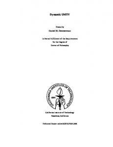
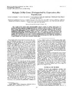
The strategy is illustrated in Fig. 1. Photosensitive substrates were irradiated for 30 min through a mask in the near UV/Vis ~l.360 nm! with a 1000 W tungsten–halogen lamp. This long exposure time is due to the low-power UV emission from the lamp. We have demonstrated that if a 364 nm Ar1 ion laser is used for irradiation, the exposure time is reduced to just a few seconds. The infrared radiation from the lamp will quickly heat up a substrate, so it was removed by passing the light beam through a water filter. For preparing macroscopic patterns, the substrates were immersed in a 55.0 mM solution of semicarbazide hydrochloride in methanol and partly covered by the mask during irradiation. Micropatterns were prepared by sandwiching the semicarbazide hydrochloride solution between the substrate and a stripepatterned chrome-on-glass mask. The resulting NH2 /NVOC patterns of deprotected and still protected amino groups could be tested by fluorescence microscopy after labeling the free-amino groups with either ATTO-TAG,17 or fluorescein by reaction with fluorescein isothiocyanate.7 For preparing binary micropatterns consisting of metal ~Pt or Au! and CdSe/CdS-core/shell NCs, the metal particles were first selectively assembled by immersing the NH2 /NVOC-patterned substrate into a solution of the particles for about 1 h. When using Au NCs, the substrate was subsequently treated with a 0.1 M solution of 1,8octanedithiol in methanol for 10 min and then again immersed into the Au particle solution for half an hour. This amplification of particle binding, where the initially assembled particles themselves served as a selective substrate, was repeated once. When Pt NCs were assembled, butylamine was added to the toluene/Pt colloidal solution up to a concentration of 0.1 M. The same procedure was used to amplify particle binding with the exception that the dithiol solution was replaced with a 0.1 M solution of 1,6hexanediamine in methanol. Here, the amplification was not repeated. After the selective assembly of the metal particles onto the substrate, a second deprotection was performed with the stripe mask oriented perpendicular to the lines of the metal
FIG. 1. Reaction scheme for the stepwise preparation of multiple particle arrays. An amino-functionalized substrate that had been protected with the photolabile NVOC group was partly deprotected by irradiation through a mask in the near UV ~I!. During deprotection the substrate was covered with a solution containing a reagent for scavenging reactive side products of the photoreaction. The substrate was then treated with a solution of amine stabilized nanoparticles, which assembled on areas of deprotected amino groups ~II!. The deprotection was repeated ~III! and another type of aminestabilized nanoparticles was assembled onto areas of freshly deprotected amino groups, yielding a binary nanoparticle array ~IV!. The cartoon depicts the assembly of patterns only a few nanocrystals wide, and was drawn this way for the sake of clarity. In fact, the written domains were actually a few microns (102 – 103 particles! wide.
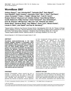
particle assemblies. The substrates were then exposed to a solution of RNCs for about half an hour, washed with solvent, and dried. The macroscopic patterns illustrated in Fig. 2 were prepared as follows. Half of a glass slide was deprotected, and the whole slide was immersed in a solution of RNCs for 30 min ~step 1!. The other half of the slide was then deprotected with a 0.2 M solution of butylamine in toluene sandwiched between the substrate and the mask ~instead of the methanolic semicarbazide solution!, because alcohols were found to irreversibly quench the luminescence of the substrate bound core/shell NCs. The whole slide was then immersed in a solution of YNCs for 45 min ~step 2!. After treating the slide for 10 min with a 0.1 M solution of 1,8-octanedithiol in toluene, it was washed with toluene and only one half of the slide ~step 3A! was dipped into Au-nanoparticle solution for 45 min to give a quaternary pattern. In a similar experiment the whole slide was dipped into a solution of RNCs for 30 min after treating the binary pattern with the dithiol ~step 3B!. After each assembly step these patterns were investi-
Downloaded 19 May 2006 to 131.215.225.175. Redistribution subject to AIP license or copyright, see http://jap.aip.org/jap/copyright.jsp
J. Appl. Phys., Vol. 84, No. 7, 1 October 1998
FIG. 2. Scheme for the preparation of macroscopic patterns for spectroscopy. First, half of a glass slide is photodeprotected to produce a substrate with amine interactions on one half, and NVOC on the other. Step 1: The slide is immersed into a solution of red-luminescent particles ~RNCs!, creating the pattern as shown. Step 2: The remainder of the slide is photodeprotected, and the slide is immersed into a solution of yellow-luminescent particles ~YNCs!, creating spatially separated regions of red and yellow particles. Step 3A: Dithiols are exchanged for the alkylamine nanocrystal surfactants, and half the slide is immersed into a solution of Au nanocrystals, producing a quaternary pattern. Step 3B: After a similar ligand exchange, the whole slide is immersed into a solution of RNCs, producing the binary pattern. The optical properties of these slides are discussed in the text and shown in Figs. 4 and 5.
gated by UV/Vis absorption and/or fluorescence spectroscopy. III. RESULTS AND DISCUSSION A. Preparation of photosensitive glass and Si/SiO2 substrates
Under the conditions we chose to functionalize glass and Si/SiO2 substrates with amino groups it was found that the trialkoxysilane 3-aminopropyltriethoxysilane polymerized and precipitated on the substrate. The use of the dialkoxysilane 3-aminopropylmethydiethoxysilane and the monoalkoxysilane 3-aminopropyl–dimethylethoxysilane usually resulted in substrate surfaces that were totally transparent and could not be distinguished from untreated slides by eye. Sometimes, however, parts of the slides showed a white precipitate when the dialkoxysilane was used, and these slides were discarded. Even the best slides, when probed by SEM, were often characterized by a small amount of submicron particulate matter on the substrate. This matter apparently originated from the surface-functionalization step. As measured by the efficiency of particle binding, the dialkoxysilanes generated a higher coverage of amino sites than the monoalkoxysilanes, and were used for most of the experiments discussed here. Although NVOC–Cl reacts readily and in high yield with primary amines in ~basic! solution, we could not react NVOC–Cl with surface-bound amino groups. Therefore, we first reacted NVOC–Cl with the amino group of glycine and then coupled NVOC–GLY to the surface-bound amino groups to prepare the photosensitive substrates.
Vossmeyer et al.
3667
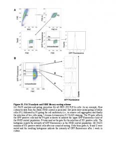
FIG. 3. Three different microscopy images of assembled and spatially separate metal and semiconductor NC arrays. ~A! Optical micrograph ~reflection mode! of a binary pattern of Au- and highly luminescent CdSe/CdS-core/ shell NCs on a glass substrate. Only the Au-NC arrays are seen because of their strong absorbance. ~B! Fluorescence micrograph of the same slide shown in part ~A!. Here, the arrays of luminescent NCs are clearly seen as bright horizontal stripes. Again, the strongly absorbing Au-NC arrays show up again as dark vertical stripes. ~C! SEM micrograph of Pt-NC arrays ~vertical stripes! and CdSe/CdS-core/shell NC arrays ~horizontal stripes! assembled on a Si/SiO2 substrate. The scale bar in part ~A! is 100 mm and is valid for all images.
B. Lithographic fabrication of patterned nanoparticle arrays
The procedure is illustrated in Fig. 1. Irradiation of the photosensitive substrates through a mask in the near UV resulted in patterns of deprotected and protected amino groups of the surface bound glycine. This pattern could be developed with fluorescent markers. If deprotection was done in air, the defined pattern was barely discernable by fluorescence microscopy. A higher yield of free-amino groups was achieved by wetting the substrate with a solution of semicarbazide hydrochloride in methanol or butylamine in toluene for the photodeprotection step. The solvates were added as scavengers for an aldehyde by-product that is presumably formed during the photodeprotection step,18 and which might rereact with the free-amino groups. When the NH2 /NVOC-patterned substrates were dipped into NC colloidal solutions, the NCs preferentially assembled on photodeprotected areas, thus undergoing a ligand exchange with the substrate-bound amino groups. By stepwise repetition of the deprotection and assembly process, micropatterns consisting of different particle arrays could be prepared. In Fig. 3, three examples of binary particle assemblies are shown, including Au- and strongly luminescent CdSe/CdS-core/shell NCs on a glass substrate, and Pt- and CdSe/CdS-core/shell NCs on a Si/SiO2 substrate. The reflection-mode micrograph @Fig. 3~A!# only reveals stripes of the Au NCs, which absorb much more strongly than the semiconductor NCs. In contrast, the semiconductor NCs appear as bright stripes in the fluorescence micrograph @Fig. 3~B!#, while the strongly absorbing Au NCs appear as dark stripes. For the SEM micrograph @Fig. 3~C!#, both the Pt NCs ~vertical lines! and the semiconductor NCs ~horizontal lines! appear with similar contrast. In order to investigate the selectivity of the method we prepared macroscopic patterns that could be analyzed by fluorescence spectroscopy. As shown in Fig. 2, we first exposed a half-photodeprotected glass slide to a solution of RNCs ~step 1!. The fluorescence intensities measured on this particular slide indicated a greater than 10/1 selectivity ratio. In other experiments, this selectivity ratio ranged from 100/1 to 8/1. The binding selectivity of the NCs depended on the
Downloaded 19 May 2006 to 131.215.225.175. Redistribution subject to AIP license or copyright, see http://jap.aip.org/jap/copyright.jsp
3668
J. Appl. Phys., Vol. 84, No. 7, 1 October 1998
type of particle, the particle concentration, the chemical composition of the NC solution, and the exposure time of the slide to the particle solution. This complexity highlights the differences that characterize selective assembly of particles rather than molecules, and is one of the major findings of this article. Selective assembly of particles onto amine-patterned substrates works well if the particle surfactants readily undergo ligand exchange with the surface amino groups. However, nanocrystal–substrate interactions and molecular– substrate interactions can be quite different. For example, spatially resolved libraries of peptides or oligonucleotides can be prepared by simply taking advantage of strong covalent chemical interactions between solution-phase molecules and substrate-bound molecules. This is not always the case for NCs. Such materials are characterized by strong interparticle and particle–substrate dispersion attractions that scale geometrically with the size of the particle.19 Such interactions can compete quite effectively with ligating particle– substrate interactions, and thus decrease binding selectivity. This can become a major problem when trying to stepwise assemble different kinds of particles onto the same substrate. Thus, the matrix of conditions for achieving spatially selective binding of multiple types of NCs to substrates is quite complex. Prolonged exposure times and high particle concentrations eventually gave strong unselective binding. On the other hand, addition of a ligating reagent ~octylamine for the semiconductor NCs; butylamine for the Pt NCs! to the particle solution usually increased the particle solubility, and thereby decreased unselective binding to the substrate. The optimum conditions for selective particle binding varied strongly from solution to solution, and thus, had to be determined for each individual particle sample by stepwise controlling the assembly process. After the red luminescent particles had been bound, the NVOC half of the slide was photodeprotected and the whole substrate was immersed in a solution of YNCs ~Fig. 2, step 2!. This immersion step was optimized by stopping it every 15 min, and monitoring the progress by measuring the yellow particle photoluminescence. When the PL intensity was in the same range as for the RNCs ~after 45 min!, the coupling reaction was stopped. The complexity of the binary pattern was increased by coupling 1,8-octanedithiol to the substrate-bound particles and redipping only one half of the slide into Au-NC solution ~Fig. 2, step 3A! or a solution of RNCs ~Fig. 2, step 3B!. Consider the metal/semiconductor pattern prepared according to Fig. 2, step 3A. This slide had four fields of different particle assemblies. Each quadrant is characterized by a unique set of optical properties, as shown by UV/Vis absorption and photoluminescence spectroscopy. Compared to the absorption spectra Y and R in Fig. 4~B! ~corresponding to the similarly labeled quadrants of Fig. 2! the absorption spectra of the quadrants Y/Au and R/Au clearly reveal the presence of Au NCs as indicated by the absorption centered at 530 nm. For comparison the UV/Vis absorption spectra of a Au-NC colloidal solution (Au(S) ) and solutions of the yellow (Y(S) ) and red (R(S) ) luminescent core/shell NCs are given in Fig. 4~A!. The PL of these various layers can be understood qualitatively within the context of a Forster cou-
Vossmeyer et al.
FIG. 4. ~A! Left: UV/Vis-absorption spectra of the red (R(S) ) and yellow (Y(S) ) luminescent CdSe/CdS-core/shell NCs dissolved in chloroform, and of Au NCs dissolved in toluene. Right: corresponding luminescence spectra of the red (R(S) ) and yellow (Y(S) ) luminescent NC solutions. ~B! Left: absorption spectra of the quaternary pattern depicted in Fig. 2 ~step 3A!. Right: corresponding luminescence spectra.
pling model for energy transfer. When the PL spectra Y and Y/Au or R and R/Au are compared, a dramatic quenching of the luminescence is observed, indicating energy transfer from the semiconductor NCs to the metal NCs. The quenching is stronger for the Y/Au pattern, consistent with the fact that the PL spectrum of the YNCs overlaps almost directly with the absorption spectrum of the Au NCs. The higher luminescence quantum yield exhibited by the yellow NCs will also lead to a slightly larger characteristic length scale for energy transfer for these particles to the Au NCs. Now consider the luminescence properties of the semiconductor-only quadrants ~Y and R! of the slide prepared according to Fig. 2, step 3A. These PL spectra are presented in Fig. 4~B!, and the solution-phase PL of those same particles are presented in Fig. 4~A!. Notice that the PL from the substrate-bound particles is asymmetric when compared to the solution-phase case. We would like to utilize this information to quantify the binding selectivity of binary patterns, but we also need to consider the role that energy transfer might play in modifying these observed luminescence intensities. In other words, if YNCs unselectively bind to RNCs, then the PL spectrum of the RNC quadrant could be affected in two ways. First, the YNCs could contribute luminescence intensity, thus skewing the RNC spectrum to slightly higher energies. In this case, the observed asymmetry in the PL spectrum gives a measurement of the nonselectivity of the second assembly step ~Fig. 2, step 2!. However, nonselectively bound YNCs could also transfer their excitation to the RNCs, thus enhancing the observed RNC quantum yield. Thus, to separate out the effect of energy transfer, we have prepared a bilayer ~YNC on RNC! structure ~Fig. 2,
Downloaded 19 May 2006 to 131.215.225.175. Redistribution subject to AIP license or copyright, see http://jap.aip.org/jap/copyright.jsp
Vossmeyer et al.
J. Appl. Phys., Vol. 84, No. 7, 1 October 1998
3669
tured nanoparticles have not proven successful. The particle bilayers depicted in Fig. 2 demonstrate the potential applicability of our technique toward the preparation of multicolored nanocrystal-based photonics devices. In fact, the technology reported here appears sufficient for patterning nanocrystal-based color pixels. As semiconductor quantum dot preparation techniques have advanced over the past few years, the range of luminescent colors that are available from these materials has also greatly expanded. We note that particles characterized by blue, green, and red luminescence spectra have all been reported. FIG. 5. Luminescence spectra of a binary pattern of YNCs and RNCs after coupling one layer of RNCs on top as illustrated in Fig. 2 ~step 3B!.
step 3B!, and compared its PL spectrum ~Fig. 5! to the RNC monolayer. We find that when YNCs are selectively bound to RNC monolayers, the luminescence quantum yield at 610 nm perhaps increased, but only by a few percent at most. This implies that energy transfer between YNC donors and RNC acceptors is not particularly important in our samples. When one considers the distance between the cores in our core/shell bilayers, the fact that energy transfer does not dominate the observed PL is not surprising.20 We thus believe that the asymmetric broadening in the spectra should give a reasonable estimate of the selectivity of binding achieved after assembling the second particle array. Using these data, and taking into account the different PL quantum yields, we calculated that the binding selectivity is around 93%. Given this selectivity, we should be able to prepare patterns with up to 4 or 5 types of particles, each spatially separated, and each giving an a relatively clean, single-type particle luminescence spectrum. It was observed that the PL intensity of the CdSe/CdS core/shell NC arrays could not be enhanced arbitrarily by a layer-by-layer coupling of particles with 1,8-ocanedithiol. Absorption spectroscopy was utilized to monitor the growth of a thin film of particles. As successive monolayers were added, however, the luminescence intensity increased only a little or, sometimes, even decreased. One possible explanation is that the thiols introduce a set of surface electronic states that couple strongly to the electronic wave functions of the nanocrystal core. These traps presumably localize charge carriers after excitation, and thereby quench the luminescence of the particles. Low-temperature luminescence measurements in our laboratory support this hypothesis. As multilayers of various thickness of core/shell NCs are cooled to 20 K, the relative PL intensities of various layers begin to reflect the thickness of the films. This argues that surface trapping in these systems is phonon assisted, similar to the case for organically passivated ~non-onion shell! semiconductor quantum dots.21 When core/shell structures are initially prepared, amine passivation has been found to positively influence luminescence quantum yields. Thus, we attempted to enhance the total luminescence intensity of our surface-bound particle multilayers by using diamines instead of dithiols for amplified particle binding. So far, however, our attempts to use diamines for amplified binding of CdSe/CdS core/shell struc-
IV. CONCLUSIONS
Amino functionalized substrates that have been blocked with the photolabile protection group NVOC can be used to prepare complex, two-dimensional nanoparticle arrays by lithographic masking techniques. The technique for producing these patterns occurs under conditions that are both ambient and chemically mild. In addition, the techniques presented here should be compatible with other lithographic patterning steps, such as those involved in the formation of electrical contacts, capacitors, and other device components that are relevant to electronics and photonics technology. Furthermore, the technique appears quite general: to date, patterns of Au, CdSe, Pt, and CdS/CdSe core/shell, and Ag particles have been prepared on glass and silicon, and indium–tin oxide ~ITO! ~Ref. 22! substrates. Other technologically relevant substrates, such as semiconducting polymers, should be relatively straightforward extensions of the procedures developed here. We are currently working on this and other aspects relevant to integrating nanocrystal assemblies into microelectronic test devices. ACKNOWLEDGMENTS
This work was part of a joint UCLA/UC Berkeley/ Hewlett Packard effort supported by an NSF-GOALI Grant. One of the authors ~J.R.H.! also acknowledges support from the David and Lucile Packard Foundation, and a Sloan Fellowship. One of the authors ~T.L.V.! would like to thank the Deutsche Forschungsgemeinschaft ~DFG! for partial support. 1
D. L. Klein, R. Roth, A. K. L. Lim, A. P. Alivisatos, and P. L. McEuen, Nature ~London! 389, 699 ~1997!. 2 R. P. Andres, T. Bein, M. Dorogi, S. Feng, J. I. Henderson, C. P. Cubiak, W. Mahoney, R. G. Osifchin, and R. Reifenberger, Science 272, 1323 ~1996!. 3 G. Markovich, D. V. Leff, S.-W. Chung, H. M. Soyez, B. Dunn, and J. R. Heath, Appl. Phys. Lett. 70, 3107 ~1997!. 4 A. P. Alivisatos, J. Phys. Chem. 100, 13226 ~1997!. 5 For a review, see, A. Henglein, Top. Curr. Chem. 143, 113 ~1988!. 6 P. C. Hidber, W. Helbig, E. Kim, and G. M. Whitesides, Langmuir 12, 1375 ~1996!. 7 S. P. A. Fodor, J. L. Read, M. C. Pirrung, L. Stryer, A. L. Lu, and D. Solas, Science 251, 767 ~1991!. 8 T. Vossmeyer, E. Delonno, and J. R. Heath, Angew. Chem. 109, 1123 ~1997!; Angew. Chem. Int. Ed. Engl. 36, 1080 ~1997!. 9 J. R. Heath, T. Vossmeyer, E. DeIonno, and G. Markovich, ACS Symp. Ser. 679, 1 ~1997!. 10 L. T. Mazzola and S. P. A. Fodor, Biophys. J. 68, 1653 ~1995!. 11 S. A. Sundberg, R. W. Barrett, M. Pirrung, A. L. Lu, B. Kiangsoontra, and C. P. Holmes, J. Am. Chem. Soc. 117, 12 050 ~1995!.
Downloaded 19 May 2006 to 131.215.225.175. Redistribution subject to AIP license or copyright, see http://jap.aip.org/jap/copyright.jsp
3670 12
Vossmeyer et al.
J. Appl. Phys., Vol. 84, No. 7, 1 October 1998
A. Patchornik, B. Amit, and R. B. Woodward, Peptides, Proceedings of the European Peptides Symposium ~North Holland, Amsterdam, 1971!, p. 12. 13 D. V. Leff, L. Brandt, and J. R. Heath, Langmuir 12, 4723 ~1996!. 14 X. Peng, M. A. Schlamp, A. V. Kadavanich, and A. P. Alivisatos, J. Am. Chem. Soc. 119, 7019 ~1997!. 15 M. R. Linford, P. Fenter, P. M. Eisenberger, and C. E. D. Chidsey, J. Am. Chem. Soc. 117, 3145 ~1995!. 16 I. Haller, J. Am. Chem. Soc. 100, 8050 ~1978!. 17 W. T. Mu¨ller, D. L. Klein, T. Lee, J. Clarke, P. L. McEuen, and P. G. Schultz, Science 272, 268 ~1995!.
18
A. Patchornik, B. Amit, and R. B. Woodward, J. Am. Chem. Soc. 92, 6333 ~1970!. 19 P. C. Ohara, D. V. Leff, J. R. Heath, and W. M. Gelbart, Phys. Rev. Lett. 75, 3466 ~1995!. 20 C. R. Kagan, C. B. Murray, and M. G. Bawendi, Phys. Rev. B 54, 8633 ~1996!. 21 M. O’Neil, J. Marohn, and G. McLendon, J. Phys. Chem. 94, 4356 ~1990!; A. Eychmuller, A. Hasselbarth, L. Katsikas, and H. Weller, J. Lumin. 48, 745 ~1991!; S.-H. Kim, R. H. Wolters, and J. R. Heath, J. Chem. Phys. 105, 7957 ~1996!. 22 S. Jia, S. W. Chung, and J. R. Heath ~unpublished!.
Downloaded 19 May 2006 to 131.215.225.175. Redistribution subject to AIP license or copyright, see http://jap.aip.org/jap/copyright.jsp