used for the compact cyclotrons developed at TRIUMF in cooperation with Ebco Technologies. The 30 MeV model adopts a solenoid-doublet (SQQ) version ...
© 1996 IEEE. Personal use of this material is permitted. However, permission to reprint/republish this material for advertising or promotional purposes or for creating new collective works for resale or redistribution to servers or lists, or to reuse any copyrighted component of this work in other works must be obtained from the IEEE.
A COMPARISON OF TWO INJECTION LINE MATCHING SECTIONS FOR COMPACT CYCLOTRONS T.Kuo, R. Baartman, L.Root, B. Milton, R.Laxadal, D.Yuan, K.Jayamanna, P.Schmor and G.Dutto, TRIUMF, Vancouver, Canada M.Dehnel, K.Erdman, Ebco Technologies Two versions of injection line matching sections between the external ion source and the spiral inflector are used for the compact cyclotrons developed at TRIUMF in cooperation with Ebco Technologies. The 30 MeV model adopts a solenoid-doublet (SQQ) version while the 19 MeV unit takes a four quadrupole/two quadrupole (4Q/2Q) option. Both cyclotrons use a same type of H- cusp source and an identical inflector-central region combination. A comparison has been made between these two systems, in terms of DC transmission and RF acceptance as a function of source's H- current intensity and emittance. The design and optics characteristics for both systems are described and the results obtained are reported.
results of this being transferred to the engineering upgrade project for the Nordion/TRIUMF TR30 cyclotron. By April 1995, 2 mA at 1 MeV was reached. II. SYSTEM DESCRIPTION A. SQQ Injection Line
The SQQ injection line was designed by Baartman [1,2,3]. The method begins with setting the physical parameters the system has to deal with. A 25 KeV injection energy was selected and this define the βγ value. The source parameters such as waist size, divergence, normalized emittance were chosen. A pair of cyclotron acceptance ellipses are calculated from an approximation in which a I. INTRODUCTION dipole magnet strength (1.2 T) and a field index (n=0.09) are The TRIUMF's TR30 central region model (CRM) is an defined. The εr from the up right ellipse approximation are exact 1 to 1 duplicate of the 30 MeV H- cyclotron's central 2 region in every respect and the highest beam energy can be given by βγν(r)((r)max) /ρ(cyc), same expression for εz. up to 1.5 MeV. The system consists of a high output (7 mA) The (r) max and (z) max are the maximum half beam size and low emittance (0.365 pi-mm-mrad) H- cusp source, a low over one betatron oscillation. ν(r), ν(z) are the betatron loss injection matching section from a SQQ design [1,2,3 ], frequency at the first turn and ρ(cyc) is the cyclotron and a large phase acceptance with good cantering inflector- parameter (20 cm). With half-size 4mm by 13 mrad at the central region. In 1990, up to 650-700 µA at 1 MeV RF source and a matched size of 1 mm radial and 1.7 mm beam with optimal beam quality has been achieved [4 ]. vertical on the first turn, the matching system must provide a The normalized circulating beam emittance εr, εz are 1 π magnification of about 1/3. This defines initially the drift and 3 π mm-mrad respectively. The centering error is no length from source waist to solenoid centre and the length more than 1.5 at 5th turn. All of these excellent design from solenoid to the entrance of the inflector. Beam matching at the first turn was studied for a number achievements resulted in a highly reliable, efficient of inflectors with the electric bend radius A and tilt cyclotron system for isotope production [5,6]. The efforts of parameter k' as free design parameters. The normalized many experts who worked on these systems with high degree circulating emittance was minimized using the computer of professionalism are duly recognized. code TRANSOPTR [9], for each transverse plane and for the we report here about the recent study on further utilization and capability development of this system since sum of the two, εr + εz. The transfer metrics for the 1993. The first is the development and tests for replacing inflector were obtained using the program CASINO [10]. just the high-power-source/ SQQ system with a simpler, By iterating matching calculations, a final system design lower-power and more compact injection system, for TR13 is defined. More detailed studies are to minimize the series cyclotrons suitable for hospital PET project emittance growth due to the transverse coupling in the installation. A 2mA source and a 4-quadrupole(4Q)/2- inflector, and due to beam orbit off-cantering. The final quadrupole(2Q) compact matching section was chosen. Up reference tune was decided as the following [2]: Source to 300 µA H- at 1 MeV was achieved by May 1993 with this waist to solenoid centr1.3 meter; solenoid centre to Q1 compact system[7,8]. Since Feb. 1994, more than 100 µA at cent 20.3 cm; Q1 centre to Q2 centre 11.3 cm; Q2 13 MeV has been obtained routinely from a TR13 cyclotron. centre to median plane 21.4 cm. Solenoid field 1.4 kG The second is to explore the SQQ system's ultimate nominal at 210 amperes; effective length23 cm and beam capability of handling large beams. In 1994, a new rotatio-80xI (ampere) degrees. Q1/Q2 pole tip field = capability of 1.5 mA at 1 MeV has been achieved. The
1858
-363/383 gauss nominal, effective length 6/10 cm and aperture diameter 5 cm.
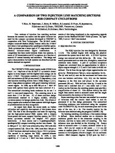
The performance of the 4Q/2Q system is summarized in Fig. 1 where the RF acceptance is plotted a function of DC current through a 20 mm collimator 40 cm from the extractor. Rotational optimization (RO) and non rotational optimization (NRO) are shown for S2E2 and for both 4Q and 2Q cases. We observed that the rotational optimization always improves the transmission. For 4Q case, curve 4 moves up to curve 2, while for 2Q case, curve 7 moves up to 6. The test results agree with the prediction that 4Q would yield smaller emittance than 2Q can. The S2E2 beam was tuncated to 20mm aperture. The DC intensity was 2mA and the corresponding normalized emittance was 0.27 π-mm-mrad. 300 µA RF beam was obtained with 15% RF acceptance. Larger Emittance beam resulted in lesser RF acceptance as curve 5 compared to curve 4. B. Tests with 4Q/2Q on TR13 Cyclotron
Fig. 1. Comparison of RF 1 MeV beam from different system In addition to the beam rotation by the solenoid, the SQQ can be rotated with respect to the inflector axis as a whole without breaking vacuum. The ion source can also be rotated with respect to the injection line. The choice of 25 KeV beam energy makes the beam transport most easily in a magnetic only injection system. The tune of beam line is almost intensity-independent up to 14 mA DC. With proper control of vacuum, space charge neutralization is maintained and in turn emittance growth due to space charge effect is minimized. B. 4Q/2Q Systems The 4Q/2Q system was designed by Dehnel et. al. [7], following the matching technique established by Baartman. The SQQ is replaced by 4 identical compact quadrupole modules, while the injection energy, the cyclotron central region, tune frequency and the inflector parameters are Fig. 2. DC transmission and RF acceptance of TR13 remained the same. Assuming an initial source waist radius cyclotron The beam tests for the TR13 cyclotron followed the of 1.5 to 2.0 mm yielded the εcnr + εcnz sum between 1.4 same procedures as exercised at CRM, but unusual results and 1.8 π-mm-mrad. For 2Q (Q1+Q2) system, the were obtained. We found the 4Q performance was inferior optimized sum value is in 3.0 to 4.0 π-mm-mrad range. to that from 2Q tuning as shown in Fig. 2. It was found that The optimization results in a system using 50 cm source the differences came from a different extraction (E3) and a waist to 1st Q drift length; 21 cm from the 4th Q to the downsized pumping system. Also the drift length increase inflector and three equal spacing of 13.5 cm between Qs. about 6 cm and the center magnetic field decreased about 1 The nominal pole face field strength for 4Q system are kG. Optimizations with Q rotation and axial position of the +290, -560 +560 and -530 gauss for Q1, Q2, Q3, and Q4 inflector exit were performed. The graphic illustration for respectively. The effective length is 10 cm with bore the improvement has been presented in a previous paper [8]. diameter of 5 cm. Again, the whole 4Q/2Q can be rotated with respect to the inflector axis. The 1st Q can also be used C. Tests With the SQQ System as skew quadrupole. III. TESTS and RESULTS A. Tests with 4Q/2Q System
The SQQ system has been vigorously studied since April 1994. After a few iterating cycles of source output and
1859
injection line optimization, a high power source-extraction S4E4 was finally developed to obtain 14mA DC beams through the inflector. This is shown in Fig. 3. The corresponding unbunched RF beam at 1.1 MeV reach 2 mA. The source normalized emittance for beam size tuncated to a 20 mm circle and 40 cm from the source exit are also shown as a function of transmitted beam. From 5 mA on the emittance increases from 0.37 π-mm-mrad to o.65 π-mmmrad at 14 mA. The cyclotron acceptance falls off from 16% to 14.2%.
Fig. 3. DC H- Thru inflector obtainable and H- obtainable at 1.1 MeV from SQQ system of CRM On the other hand, when the beam intensity is small the emittance value is also high (0.46 π-mm-mrad at 0.4 mA). But the transmission is still maintained at 16% revealing that space charge effect causes emittance growth at high beam. The RF system at CRM does not have enough power to hold 50kV and 2.2 kW of RF beams at 1.1 MeV at the same time, the dee voltage is believed to be less than 50 kV, which in turn contributes to the fall-off of acceptance. IV. DISCUSSION From the 4Q/2Q tests with the TR13 cyclotron, sufficient beam current of 220 µA at 1 MeV (210 at 13 MeV) has been achieved at only 7 amp arc power. For normal factory procedure and routine operation, 150 µA has been obtained without test optimization. The 2Q option met all the requirements for the TR13 and it was the most cost
effective solution for 100 µA only specification. As a result, it becomes the TR13 designated injection line. For RF beam current exceeding 1 mA, the SQQ system is the one of choice. The SQQ system possesses certain optical capability that the 4Q/2Q would not have, i.e., a larger bore diameter in the solenoid, a stronger focusing lens and the beam rotation when passing through the solenoid field. The beam shape from the source-extraction system has been assumed a cylindrical symmetry. This is true only if the beam intensity is small. At high ion source power and high extracted beam current, the beam shape appears to be elliptical. The solenoid rotates this beam about 160 degree at 200 amperes, matching the transverse plane to those of the doublet. Thus the source axis rotation, the SQQ rotation with respect to the inflector entrance axis and the beam rotation in the solenoid give a optimal matching capability. In conclusion, the compact 4Q/2Q systems perform well with smaller beam intensity, while the SQQ system has a higher beam handling capability. V. REFERENCE [1] R. Baartman, "Matching of Ion Sources to Cyclotron Inflectors", Proc. 1st European Part. Acc. Conf., pp. 947948, Rome, 1988. [2] R. Baartman, "TR30 Injection Line Optics", TRIUMF Design Note, TRI-DN-89-25, 1989. [3] R. Baartman et. al., "a 30 MeV H- Cyclotron for Isotope Production", Proc. of the IEEE Particle Accelerator Conference, Chicago, 1989, P.1623. [4] W. Kleeven et al, "Status and Results from thr TR30 Cyclotron Centre Region Model", Proc. 2nd European Part. Acc. Conf., pp.434-436, Nice, 1990. [5] H.R. Schneider et. al., "A Compact H- Cyclotron for Isotope Production", Proc. 1st European Particle Accelerator Conference, Rome, 1988, p. 1502. [6] B.F. Milton et. al., "First Beam in a New Compact Intense 30 MeV H- Cyclotron for Isotope Production", Proc. 2nd European Particle Accelerator Conference, Nice, 1990, p. 1812. [7] M. Dehnel et. al., "Injection System Design and Tests for the TR13 Cyclotron" proc. 4th European Particle Accelerator Conference,London, 1994. [8] T. Kuo et. al., "Performance of an ISIS System using Compact Magnetic Quadrupole". proc. 4th European Particle Accelerator Conference, London, 1994. [9] E.A. Heighway and R.M. Hutcheon, "TRANSOPTR-A second Order Beam Transport Design Code with Optimization and Constraints", Nucl. Inst. Methods , 187, 89, 1981. [10] B.F. Milton & J.B. Pearson, "CASINO: Calculation of Spiral Inflector Orbits", TRIUMF Design Note, TRI-DN89-19, 1989.
1860