INTERNATIONAL CONFERENCE ON ENGINEERING DESIGN, ICED’07 28 - 31 AUGUST 2007, CITÉ DES SCIENCES ET DE L'INDUSTRIE, PARIS, FRANCE
A COMPUTATIONAL FRAMEWORK FOR SEMANTICALLY RICH DESIGN PROBLEMS BASED ON THE THEORY OF AFFORDANCES AND EXEMPLAR TECHNOLOGY Jonathan R.A. Maier1, Srinivasan Anandan1, Vikram Bapat2, Joshua D. Summers1 and Bernhard Bettig3 1
Department of Mechanical Engineering, Clemson University Mechanical Engineering-Engineering Mechanics Dept., Michigan Technological University 3 Department of Mechanical Engineering, West Virginia University Institute of Technology 2
ABSTRACT In this paper we discuss the conceptual basis for an integrated design environment that includes computationally intensive activities (simulation, analysis, solid modeling), as well as less computationally intensive activities (problem definition, requirements modeling, rationale capture), etc. Moreover, geometric information and semantic information are linked in this environment, in a seamless framework that empowers the designer to create geometries, create semantic relationships, and trace and manipulate the connections between geometric entities and semantic relations of interest. Toward this goal, a computational environment that supports semantically rich design is described. In this paper we discuss the concept of affordance as a relational formalism to capture semantic information. We also discuss exemplar technology as an appropriate formalism to manipulate semantic information within a CAD environment. Current CAD systems do not allow for artifacts to be placed in context. Various contexts include the artifact’s use by people, the artifact’s relationship in the environment (especially with respect to sustainability issues), how the artifact is manufactured, and the artifact’s life cycle issues such as maintenance, recycling, eventual disposal, etc. These various contexts for the artifact are semantically rich. A geometric description alone does not carry semantic information. In our framework, design exemplars implement affordances in the computational environment, thus providing a mechanism to tie concrete product information to contextual information thereby enabling the capture and manipulation of semantic information within the computational environment. Keywords: Semantics, computational environment, affordances, design exemplars 1
INTRODUCTION
1.1 Capabilities of current design environments In this paper we report our preliminary findings in our on-going research to develop the conceptual basis and computational framework to enable semantically rich design. Current Computer-AidedDesign (CAD) systems typically only include geometric information and, depending upon the particular CAD system, various relationships between geometric features such as assemblies, parametrics, constraint equations, etc. However, semantic information (what the geometry means to the designer, to end users, with respect to requirements, ramifications for DFX methods, etc.) is not integrated into existing CAD systems. As an example, engineering reports are semantically rich but the information contained within is not linked explicitly to the geometric models. This creates a situation where current CAD systems do not allow for artifacts to be placed in context. Various contexts include the artifact’s use by people, the artifact’s relationship in the environment (especially with respect to sustainability issues), how the artifact is manufactured, and the artifact’s life cycle issues such as maintenance, recycling, eventual disposal, etc. These various contexts for the artifact are semantically rich. A geometric description alone does not carry semantic information.
510 ICED’07/875
1
1.2 Literature Review The semantic nature of design problems has been studied for nearly three decades [1]. The engineering information that is used comes from many sources and in many forms: Specifications, Proposals, Milestone Design Reports, Engineering Reports, Process Descriptions, Bill of Materials, or CAD/CAM/CAE models. All of this information is now maintained electronically, usually in databases from which it is available almost anywhere worldwide, at almost every manufacturing company and similar information is maintained in the service industry. However, most of this information is currently only available in human-readable terms. Currently there are international efforts to standardize how semantic information is represented. For example, the semantic web built on the world-wide web is intended to allow publishing information in a computer-interpretable way [2, 3]. Essentially the Semantic web is based on storing information as assertions similar to subject-verbobject phrasing in a natural language sentence. However, the information is in a computerinterpretable form of thing-property-value where the allowable values for each of these arguments is dictated by an XML schema also published on the web. Once the semantic web is in place it should be possible to create queries that are answered by automatically searching for integrated bits of knowledge from all over the web. In a similar effort, Microsoft is working to incorporate semantic information in their word processor application where certain information, such as names or addresses, can be tagged in the document using “smart tags”, thereby supporting actions that are normally performed in other applications. Product Data Management (PDM) software such as NX3 by Unigraphics [4] and Wildfire by Parametric Technology Corporation [5] also allow creating “smart models” in which information can be associated with objects such as parts, features, and geometric primitives in the form of property-value in which property is a text string and value can be a numeric value, a Boolean value (true/false), or a text string. In non-engineering contexts, the semantic modeling approach has been used in diverse domains to intelligently access multi-media content [6, 7], crystolographic data [8], and semantically rich medical knowledge [9, 10]. In engineering, work has been done to provide a semantically rich integration from CAD to CAE analysis models [11]. The authors and others have investigated adding information about “ports” to component models to automate the assembly of models for design and analysis [12, 13]. A recent review of knowledge management tools, including non-expert systems for simply accessing/searching for information and expert systems for actually generating/optimizing designs, shows that most of the work does not address semantics [14]. In general Engineering is “cybertrailing” other fields that are embracing the cyber infrastructure [15]. This may be because of how heterogeneous engineering information can be, how complicated engineering information can be considering the complicated geometry that is designed, complicated engineering analyses (e.g., FEA and CFD), complicated interactions between systems, and the need to not only extract information but to do analyses and use analyses to synthesize designs. Current research has focused on the issues of representing and extracting semantic knowledge and information used and generated during engineering design. However, little work appears in the literature specifically targeting using this semantic information to evaluate and synthesize designs, thereby driving the design process. 1.3 Our vision for capabilities of a semantically rich design environment Ultimately, the goal is to create an integrated design environment that includes not only the computationally intensive activities (simulation, analysis, solid modeling), but also the less computationally intensive activities (problem definition, requirements modeling, rationale capture). Moreover, geometric information and semantic information should be linked, in a seamless framework that empowers the designer to create geometries, create semantic relationships, and trace and manipulate the connections between geometric entities and semantic relations of interest. Toward this goal, a computational environment that supports semantically rich design is needed. We envision that this will lead to a CAD environment enabling semantic information to be represented in a structured way, allowing the computer to use the semantic information directly to evaluate the product being designed, to detect conflicts between the design and its requirements, and to change automatically the design to be consistent with the requirements. For this research we are utilizing the concept of affordance as a relational formalism to capture semantic information. We are also utilizing exemplar technology as an appropriate formalism to
510 ICED’07/875
2
manipulate semantic information within a CAD environment. These concepts are explained in more detail in the next two sections. 2 THEORETICAL BASIS: THE THEORY OF AFFORDANCES The theory of affordances was originally proposed by the perceptual psychologist J.J. Gibson [16]. Since its introduction, the concept of affordance has been adopted as a useful formalism in diverse research areas including childhood development (cf., [17]), artificial intelligence (cf., [18]), industrial design (cf., [19, 20]), human-computer-interaction (cf., [21-24]), and most recently engineering design in a series of papers by the authors [25-29] which has also sparked some interest among other researchers (cf. [30, 31]). Briefly stated, an affordance is what one system (say, an artifact) provides to another system (say, a user, or even another artifact). Simple examples of affordances are that knobs afford turning, keyboards afford typing, and iron affords casting. The concept of affordance thus allows us to describe a broad array of semantically rich relationships that exist in design; relationships in and between designers, artifacts, and users. These relationships are shown in Figure 1, which depicts the Designer-Artifact-User (DAU) complex system [29].
Designer(s)
ne
Ar tif ac
tp
es
ro
c an
pe
rd
r ti es
o Aff ed ed
Artifact(s)
AUA
User(s)
AAA
DAU System
Figure 1. Designer-Artifact-User (DAU) Complex System showing affordance relationships
The Designer-Artifact-User complex system has been elaborated in more detail in previous work by the authors [29]. An important result is that this formalism is also a Complex Adaptive System (CAS) following the same cycle as other CAS (cf., [32]). Within a DAU system, relationships between artifacts and users are described as artifact-user affordances (AUA) which indicate what uses the artifact provides to the user. As in all affordances, AUA can be either positive or negative, depending upon whether the potential behavior is beneficial or harmful to the user. Positive affordances must be designed into the artifact, while negative affordances must be designed against. Therefore, an important task for designers is to ascertain from users what positive affordances should be designed and what negative affordances must be designed against. Relationships in-between artifact subsystems are described as artifact-artifact affordances (AAA). These affordances describe what artifact behaviors are possible depending upon the structure of the artifact subsystems. Five general properties of affordances have been identified: complementarity, which says that an affordance exists between two or more subsystems, not in isolation; imperfection, which says that there is no such thing as a perfect affordance; polarity, which says that affordances can be either positive or negative;
510 ICED’07/875
3
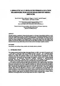
multiplicity, which says that multiple affordances can be associated with a particular subsystem; and quality, which describes how well a particular behavior is afforded. The central idea of Affordance Based Design is that design is the specification of a system structure that possesses certain desired affordances in order to support certain desired behaviors, but does not possess certain undesired affordances in order to avoid certain undesired behaviors. By changing the structure of a system, designers can change the system’s affordances. The affordances, in turn, determine how the system can potentially behave. Designers define the structure of a system, and thus its affordances, and thus how not only the artifact will behave but also how the user will behave with the artifact. The affordances of a computer monitor stand (see Figure 2) analyzed by the investigators in previous research [28] are shown in Table 2. The structure of the monitor stand determines, for example, whether it is strong enough to support a 21 inch monitor, whether it will be damaged by a monitor dropping on it, and whether it is usable and aesthetically pleasing. A diagrammatic representation of the information that could be required to ascertain whether these affordances are met is shown in Figure 3.
Figure 2. Conventional computer monitor stand
The state of the art in affordance based design, however, is still mostly theoretical. Limited methodological support is offered based upon the underlying theory (cf., [27]). The most pressing need therefore is to operationalize the theory and basic methods to enable designers to use affordances in practical design settings. Our research serves to meet this need by incorporating affordances into a semantically rich CAD environment. Table 1. Hierarchical affordance structure for the monitor stand Priority
1
2 3
510 ICED’07/875
Positive Affordances: (The artifact must afford…) The use of up to a 21 inch (CRT) monitor; A view of the monitor vertically as close as possible to its height on the desk without a PCDSMS. Access to buttons, levers, and ports on the PC and docking station; Human use; Manufacture. Aesthetics; Improvement; Maintenance; Retirement; Sustainability.
4
Negative Affordances: (The artifact must NOT afford…) Additional weight onto the laptop computer; Interference to the portable computer and docking station beneath it. Damage when a monitor is dropped from a height of three inches on it; Human injury / frustration. Product degradation.
• • • • • •
Exterior dimensions Thicknesses Material properties Visual cues Labels …
Affords usability?
Model of Artifact (Computer Stand)
• • • • • •
Visual acuity Hand dexterity Arm strength Range of motion Coordination skills … Model of User
Figure 3. Artifact (computer stand) and user models related through the affordance of usability
3 COMPUTATIONAL BASIS: EXEMPLAR TECHNOLOGY The design exemplar is a powerful, generic data structure co-developed by the authors to represent, verify, and manipulate geometric, algebraic, and physical design characteristics in design problems [33-35]. For example, designers, using exemplars, can find geometric properties (e.g., walls with a specific thickness) in CAD models and then change these properties as needed (e.g., the wall thickness from 0.1” to 0.5”). To this end, exemplars first represent design characteristics by defining the objects and relationships that must exist explicitly in the design model when the design has the given characteristic. The design exemplar is a conduit between the model of the artifact, here represented in a geometric CAD model, and these characteristics of interest. As an example, the Designed_Offset_Faces exemplar (Figure 4) defines a characteristic in which there exist in the design model two faces (f1 and f2), that have been explicitly constrained by the designer to be offset from one another. In the graph, round nodes are used to represent objects and square nodes are used to represent relationships or constraints, which can be unary, binary, or n-ary. Once an exemplar has been defined, a pattern matching algorithm (e.g., [36]) can be executed to identify faces in the design that the designer has offset. The exemplar pattern can also contain sub-patterns that (a) repeat themselves in the design, (b) occur in alternative or optional ways, or (c) must not exist in the design. Face f1
PARALLEL_OFFSET
Face f2
Explicit Face f1; Face f2; PARALLEL_OFFSET (f1, f2)
Figure 4. “Designed_Offset_Faces” exemplar
A design exemplar can also describe objects and relationships that are implicit in the design product model. For example, Figure 5 shows an exemplar, “Offset_Faces,” in which two faces exist in the design that are implicitly offset. That is, they happen to be offset in the design, but are not directly being controlled to be so. To find instances of patterns with implicit relationships, pattern matching must be combined with solving and evaluating constraints. Specialized domain-specific solvers are called by a generic solving algorithm. Implicit objects and relationships are shown with non-filled shapes (circles/squares) and dashed lines in the exemplar graph.
510 ICED’07/875
5
Face f1
PARALLEL_OFFSET
Face f2
Explicit Face f1; Face f2; Implicit PARALLEL_OFFSET (f1, f2)
Figure 5. “Offset_Faces” exemplar
Besides distinguishing explicit and implicit characteristics, a design exemplar also distinguishes what a design is like when it has the described characteristic and when it does not. For example, Figure 6 shows an exemplar distinguishing between faces that have been designed to be offset and those that have not. The “valid” and “invalid” parts of a design exemplar describe the two situations: valid, where the identified faces are explicitly designed to be offset, and invalid, where the identified faces are not explicitly designed to be offset. The “valid” and “invalid” parts enable modifying or enforcing a design characteristic in terms of both the existence of objects and relationships and the values of attributes. Modification can include changing values (e.g., modify hole diameters) or changing existence (e.g., add or delete holes). Face f1
Face f1
PARALLEL_OFFSET
PARALLEL_OFFSE T
Face f2
Face f2
NO T
“Valid” Component
“Invalid” Component
Explicit Face f1; Face f2; Explicit (Valid Only) PARALLEL_OFFSET (f1, f2) Explicit (Invalid Only) NOT BLOCK PARALLEL_OFFSET (f1, f2)
Figure 6. “Complete_Designed_Offset_Faces” exemplar
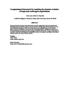
Figure 7 illustrates in textual format a more sophisticated exemplar we have used to identify faces that compose a “thin wall” for casting manufacturability analysis. The explanation of this exemplar is provided to illustrate the portions of the entity-relation sub-graphs that are used to verify different conditions required of the “thin wall” characteristic. Exemplars have been used in a variety of applications including feature recognition, modeling standard embodiment design procedures, design for manufacturing validation, as a query language and case-based reasoning [37-40]. So far, exemplar technology has been used for single task problems such as (i) identifying design objects with a given characteristic (e.g., undercut faces), (ii) evaluating design properties (e.g., length of a duct), (iii) validating designs (e.g., not too big), (iv) comparing two designs with respect to a characteristic (e.g., which model has greater surface to volume ratio), and (v) modifying a design (e.g., to have or not have a fillet). While there are advantages of using the design exemplar, certain limitations do exist. First, the level at which exemplars are developed is extremely detailed. A second limitation is that the vocabulary of the design exemplar is limited to only geometric and parametric entities and relations that are solvable with constraint solving systems, thereby excluding more semantically focused vocabulary elements.
510 ICED’07/875
6
Further, it is possible to create exemplars that have conflicting relations (face 1 and face 2 are both parallel and perpendicular). A final limitation is that the design exemplar must be actively employed by the designer to check the validity or modify a design model.
CP: three planes are highlighted for a “thin wall”
7
CP: two edges are “overlapping” (one of the end vertices on one edge is between the vertices of the second edge)
510 ICED’07/875
CP: dist. at top surface is less than 0.10 units
Figure 7: “Thin_Wall” exemplar
Constraint Problem (CP): wall edge surfaces are facing opposite directions
eq_1: angle < 190 degrees eq_2: angle > 170 degrees eq_3_1: thickness < 0.10 eq_3_2: thickness ≥ 0.10 eq_4: dist_1 = dist_2 + dist_3
Explicit in artifact model Three planes, connected through two lines which are not on the same loop for the middle plane
Explicit: Solid Body; Plane First_Surf; Plane Second_Surf; Plane Top_Surf; Line First_Edge; Line Second_Edge; Point First_V1; Point First_V2; Point Second_V1; Point Second_V2; BOUNDARY (Body, {First_Surf, Second_Surf, Top_Surf}); BOUNDARY (First_Surf {First_Edge}); BOUNDARY (Second_Surf {Second_Edge}); BOUNDARY (Top_Surf {First_Edge}); BOUNDARY (Top_Surf {Second_Edge}); BOUNDARY (First_Edge {First_V1, First_V2}); BOUNDARY (Second_Edge {Second_V1, Second_V2}); Implicit: Vector “First_Vec”; Vector “Second_Vec”; Parameter “angle”; TC_SURF_NORMAL (First_Vec, Body, First_Surf); TC_SURF_NORMAL (Second_Vec, Body, Second_Surf); ANGLE (angle, First_Vec, Second_Vec); EQUATION “eq_1” (angle); EQUATION “eq_2” (angle); Parameter “thickness”; PARALLEL (First_Edge, Second_Edge); DISTANCE (thickness, First_Edge, Second_Edge); Implicit (Valid Only): EQUATION “eq_3_1” (thickness); Implicit (Invalid Only): EQUATION “eq_3_2” (thickness); Implicit: Point “Between”; Line “perpendicular”; Parameter “dist_1”; Parameter “dist_2”; Parameter “dist_3”; PERPENDICULAR (perpendicular, First_Edge); INCIDENT (Between, perpendicular); INCIDENT (Between, Second_Edge); INCIDENT (First_V1, perpendicular); DISTANCE (dist_1, Second_V1, Second_V2); DISTANCE (dist_2, Second_V1, Between); DISTANCE (dist_3, Between, Second_V2); EQUATION “eq_4” (dist_1, dist_2, dist_3); ID “thin wall” (First_Surf, Second_Surf, Top_Surf);
4. NEW EXEMPLAR DATA STRUCTURES AND ALGORITHMS The exemplar representation has been extended in three previous projects in an attempt to provide different levels of abstraction and usability of the design exemplar. First, exemplar networks have been introduced as a tool for assembling atomic exemplars (exemplar nodes) into more complex constructs, which in turn are compiled into a new integrated exemplar [39]. Secondly, the exemplar representation was extended to support logical connectives (AND, OR, NOT, XOR) thereby introducing a more flexible approach to defining characteristics of interest [38, 41]. Finally, a procedural representation has been developed for allowing exemplar developers the flexibility of sequencing distinct exemplars, chaining them based upon the results of their queries [42]. As mentioned earlier, user and artifact properties are necessary for defining artifact-artifact and artifact-user affordances. As an example, consider a scenario of holdability for a fully-abled user. In this case, a handle may be defined to have acceptable size range of 1” to 5”. However, for elderly users, this definition should be replaced with one that defines a different size range, perhaps 3” to 5” based upon arthritic considerations. Many other affordances, and their defining exemplars, may also need to be replaced or updated when the user of the artifact (and hence the user’s properties) is redefined. Three possible avenues for supporting affordance specific exemplars have been identified: 1. Directory structure to hold related exemplars hierarchically according to artifact and user specific information, 2. Create extensive sets of OR condition blocks to accommodate different artifact and user property values 3. Move beyond the current “valid/invalid” representation to include “valid in scenario A/valid in scenario B…” The exemplar algorithm is based on the premise of forming a series of constraint problems to check the validity and to satisfy the desired value propagation. As such, sets of exemplars may be validated against each other to determine possible conflicts within their respective constraint problems. For example, one exemplar may determine that thin wall should be greater than 0.1” (casting requirement), while another exemplar may stipulate that the distance between two planes be set at 0.08” (size requirement). In this situation, these two exemplars could be determined to be in conflict based on their constraint problems. As there may be conflicting affordances (requirements) identified in the design problem, these conflicts may be elicited through the use of exemplar modeling of these affordances. 5. MAPPING AFFORDANCES TO EXEMPLARS In addition to investigating the different structuring of the exemplar as a tool for representing affordances, it is important to examine how or whether it is necessary to delineate between artifactartifact affordances and artifact-user affordances. Consider a design exemplar for representing a thin wall that has been developed to be used in determining a component’s fixturability. This exemplar is a specific affordance between two artifacts: component and manufacturing process. Likewise, a thin wall exemplar can be authored to be used to define the affordance of holdability of a consumer product such as a power tool (the wall thickness of the handle should not make it too fragile). This second exemplar has the purpose of specifying an affordance between the artifact and the user. In this manner, the same general concept of fixturability or holdability can be captured in an exemplar. Figure 7 illustrated a simple thin wall exemplar that can be used to help define holdability. When discussing the holdability of an artifact, several different characteristics must be considered. These characteristics are interdependent. First, the overall size of the artifact can impact the holdability. However, a larger size is allowed if there are handles for the artifact. Further, the strength of the object can be assessed as an issue in holdability. Something may be too fragile to hold, if it consists of several thin walls, for example. However, if these thin walls are re-enforced then, the strength increases and the holdability increases. Table 3 illustrates a few exemplars that may be combined to create a definition for holdability affordances. Applying the exemplars in each row affects (parametrically) the interpretation of the exemplars marked with “Changes meaning”.
510 ICED’07/875
8
Table 2: Exemplars for the affordance of holdability Thin Walls
Large Size
Existence of Support Ribs
Sufficient Handles
Existence of Sharp Edges
Changes meaning
Thin Walls
Changes meaning
Large Size Existence of Support Ribs
Changes meaning
Sufficient Handles
Changes meaning
Existence of Sharp Edges
Changes meaning
Five exemplars are defined for the holdability affordance: (1) check for the existence of thin walls based upon a defined value for “thin”, (2) overall size of the design product, (3) existence of reinforcing ribs on the thin wall, (4) number of handles on the design product, and (5) existence of sharp edges on the design product. The defined value for “thin” in the first exemplar will decrease in value as the number of reinforcing ribs increases. In this manner, the structural strength of the part is maintained at an acceptable holdable level. Thus, the relationship between these two exemplars is inversely related as the meaning changes. In other words, the results from applying the exemplars in the rows will affect the affordances of the columns. On the other hand, the exemplars for overall size and number of handles are related. As the size increases, the number of required handles will increase to ensure that it is easier to hold. Thus, it is important to not just collect a set of exemplars that each represent a geometric characteristic (affordance) under a predescribed set of conditions, but it is also important to link these characteristics together so that they evolve and change as the design is modified. In this manner, composite models of the system of exemplars are required, not simply chaining of the exemplars (Figure 8). user visual acuity product # Handles exemplar Thin wall exemplar
component
geometry
• • • • •
Geometric description Topologic description Material properties Annotations …
age
kinematic model
Overall size exemplar
Affords Holdability?
geometry
• • • • •
Visual acuity Hand dexterity Arm strength Range of motion … Model of Users
Model of Artifact
Figure 8. Exemplar as a representation for checking artifact model variables for existence or value
510 ICED’07/875
9
The exemplar can be combined through logical connectives, such as AND, OR, NOT Blocks as seen in [38, 41], and also through sequentially linked production systems as has been recently developed at Clemson University [42]. 6. CONCLUSIONS In this paper we have discussed the conceptual basis for a computational framework to enable semantically rich design. Having thus established the vision, theory, and supporting technology for a semantically enabled computational environment, our current research is focused on identifying specific classes of semantic information to support and domains of interest, as reported in [43]. Our efforts so far have included analyses of patents, requirements, and student design reports. Actual implementation of the extended exemplar formalism to enable semantic design tasks remains as future work. 7. ACKNOWLEDGEMENTS This work is supported by NSF grant # 0636407. REFERENCES [1] Bhaskar R. and Simon H. A. Problem Solving in Semantically Rich Domains: An Example from Engineering Thermodynamics, Cognitive Science, 1977, 1, 193-215. [2] Berners-Lee T. Semantic Web Roadmap. http://www.w3.org/DesignIssues/Semantic.html, accessed: Jan 29, 2006. [3] Berners-Lee T., Hendler J. and Lassila O. The Semantic Web - A New Form of Web Content that is Meaningful to Computers will Unleash a Revolution of New Possibilities. Scientific American, May, 2001. [4] UGS. UGS - Product Life Cycle Management Solutions. http://www.ugs.com, accessed: September, 2005. [5] PTC. PTC: Product Lifecycle Management (PLM) Sofware Solutions. http://www.ptc.com, accessed: January, 2006. [6] Wallace M., Athanasiadis T., Avrithis Y., Delopoulos A. N. and Kollias S. Integrating Multimedia Archives: The Architecture and the Content Layer. IEEE Transactions on Systems, Man, and Cybernetics, Part A: Systems and Humans, 2006, 36(1). [7] Parmar M. J. and Angelides M. C. Automatic Feature Extraction to an MPEG-7 Content Model, International Conference on Internet and Multimedia Systems and Applications, Honolulu, HI, 2005. pp. 448-53 (IMSA). [8] Mcmahon B. Semantically Rich Metadata in Crystallographic Publishing, EUNIS 2005 Leadership and Strategy in a Cyber-Infrastructure World, Manchester, UK, 2005 (EUNIS). [9] Klein M., and Aleksovski Z. Using Lexical and Logical Methods for the Alignment of Medical Terminologies, Lecture Notes in Artificial Intelligence, 2005, 3581: 241-5. [10] Siadat M. R., Soltanian-Zadeh H., Fotouhi F. and Elisevich K. Content-Based Image Database System for Epilepsy. Computer Methods and Programs in Biomedicine, 2005, 79(3): 209-26. [11] Bajaj M., Fulton R. and Peak R. Customizing Next-Generation Multidisciplinary Product Realization Frameworks, Design Engineering Technical Conferences, Chicago, IL, 2003, pp. 189-98 (ASME). [12] Singh P. and Bettig B. Port-Compatibility and Connectability-Based Assembly Design, ASME Journal of Computing and Information Science in Engineering, 2004, 4(3): 197-205. [13] Liang V. C. and Paredis C. A Port Ontology for Automated Model Composition", Winter Simulation Conference, 2003, New Orleans, LA (WSC). [14] Benson M. and Terpenny J.P. A Survey of Methods and Approaches to Knowledge Management in the Product Development Environment, Design Engineering Technical Conferences, Pittsburgh, PA, 2001 (ASME). [15] Regli W. EXchanging Cyber-Infrastructure Themes in Engineering Design Final Report, NSF EXCITED Workshop, Arlington, VA, 2005. (NSF). [16] Gibson J.J. The Theory of Affordances, in The Ecological Appraoch to Visual Perception, 1979 (Houghton Mifflin, Hopewell, NJ). [17] Gibson E.J. Perceptual Learning in Development: Some Basic Concepts. Ecological Psychology, 2000, 12(4): 295-302.
510 ICED’07/875
10
[18] Murphy R.R. Case Studies of Applying Gibson's Ecological Approach to Mobile Robots, IEEE Transactions on Systems, Man, and Cybernetics, Part A: Systems and Humans, 1999, 29(1): 105-11. [19] Norman D.A. The Design of Everyday Things, 1988, (Currency Doubleday, New York). [20] Norman D.A. Affordances, Conventions, and Design. Interactions, 1999, 6(3): 38-43. [21] Lintern G. An Affordance-Based Perspective on Human-Machine Interface Design. Ecological Psychology, 2000, 12(1): 65-9. [22] Hartson H.R. Cognitive, Sensory, and Functional Affordances in Interaction Design. Behavior and Information Technology, in press. [23] Gaver W.W. Technology Affordances, Proceedings of CHI'91, New Orleans, LA, pp.79-84 (ACM). [24] Flach J.M., Hancock P.A., Caird J.K. and Vicente K. The Ecology of Human-Machine Systems, 1995 (Lawrence Earlbaum, Hillsdale, NJ). [25] Maier J.R.A. and Fadel G. Affordance: The Fundamental Concept in Engineering Design Design Engineering Technical Conferences, Paper no. DTM-21700, Pittsburgh, PA, 2001 (ASME). [26] Maier J.R.A. and Fadel G. Comparing Function and Affordance as Bases for Design, Design Engineering Technical Conference, Paper no. DTM-34029, Montreal, Cananda, 2002 (ASME). [27] Maier J.R.A. and Fadel G. Affordance-Based Methods for Design, Design Engineering Technical Conferences, Paper no. DTM-48673, Chicago, IL, 2003 (ASME). [28] Maier J.R.A. and Fadel G. A Case Study Contrasting German Systematic Engineering Design with Affordance Based Design, Design Engineering Technical Conferences, Paper no. DTM84954, Long Beach, CA, 2005 (ASME). [29] Maier J.R.A. and Fadel G. Understanding the Complexity of Design, in Complex Engineered Systems: Science Meets Technology, Braha, Minai and Bar-Yam (eds), 2006 (Springer, New York). [30] Galvao A.B. and Sato K. Affordances in Product Architecture: Linking Technical Functions and User Requirements, Design Engineering Technical Conferences, Paper no. DTM-84525, Long Beach, CA, 2005 (ASME). [31] Brown D.C. and Blessing L. The Relationship between Function and Affordance, Design Engineering Technical Conferences, Paper no. DTM-85017, Long Beach, CA, 2005 (ASME). [32] Gell-Mann M. Complex Adaptive Systems, in Complexity: Metaphors, Models, and Reality, Cowan, Pines and Meltzer (eds), 2004 (Addison-Wesley, New York). [33] Bettig B., Shah J.J. and Summers J.D. Domain Independent Characterization of Parametric and Geometric Problems in Embodiment Design, Design Engineering Technical Conferences, Paper no. DAC-14259, Baltimore, MD, 2000 (ASME). [34] Bettig B., Shah J.J. and Summers J.D. Geometric Exemplars: A Bridge Between AI and CAD, in From Knowledge Intensive CAD to Knowledge Intensive Engineering, Cugini and Wozny (eds), 2001 (Kluwer Academic Press, the Netherlands). [35] Summers J.D., Shah J.J. and Bettig B. The Design Exemplar: A New Data Structure for Embodiment Design Automation. Journal of Mechanical Design, 2004, 126(5): 775-87. [36] Joshi S. Feature Recognition and Geometric Reasoning for some Process Planning Activities, in Geometric Modeling for Product Engineering, Wozny, Turner and Preiss (eds), 1990 (Elsevier Science Publishers, North-Holland). [37] Venkatamaran S., Summers J.D. and Shah J.J. An Investigation of Integration of Design by Features and Feature Recognition, Feature Modeling and Advanced Design for Life Cycle Systems, Valenciennes, France, 2001 (IFIP). [38] Divekar A. and Summers J.D. Logical Connectives for a CAD Query Language: Algorithms and Verification, Design Engineering Technical Conferences, Paper no. CIE-57787, Salt Lake City, UT, 2004 (ASME). [39] Summers J.D. and Shah J.J. Exemplar Networks: Extensions of the Design Exemplar, Design Engineering Technical Conferences, Paper no. CIE-57786, Salt Lake City, UT, 2004 (ASME). [40] Summers J.D., Lacroix Z. and Shah J. J. Case-Based Design Facilitated by the Design Exemplar, International Conference on Artificial Intelligence in Design, Cambridge, UK, 2002, pp. 453-476 (Kluwer Academic Press). [41] Divekar A. and Summers J.D. Investigation of the Design Exemplar as a CAD Query Language,
510 ICED’07/875
11
International Conference on Engineering Design, ICED ‘03, Paper no. 1109. Stockholm, Sweden, 2003 (The Design Society). [42] Putti S. and Summers J.D. Dynamic Networks: Procedural Representation of the Declarative Design Exemplar. Technical Report, 2006 (Clemson University - Automation in Design Lab). [43] Anandan S., Maier J.R.A., Bapat V., Bettig B. and Summers J.D. Semantics in Engineering Design, International Conference on Engineering Design, ICED ’07. Paris, France, 2007 (The Design Society). Contact: Joshua D. Summers Clemson University Department of Mechanical Engineering 250 Fluor Daniel Building Clemson, SC 29634-0921 USA Phone: 864-656-3295 Fax: 864-656-4435 e-mail:
[email protected] URL: http://aid.ces.clemson.edu
510 ICED’07/875
12