A Framework For Mission Level Design Thomas Liebezeit Volker Zerbe Department of Automatic Control and System Engineering Department of System and Control Theory TU Ilmenau, Germany TU Ilmenau, Germany email:
[email protected] email:
[email protected] Tino L¨offler Departmant of Media Technology TU Ilmenau, Germany email:
[email protected] ABSTRACT In this paper we present the idea of Mission Level Design (MLD) for complex systems. MLD can be thought of as a test of a system design on an abstract level. Therefore, the simulation of an overall system model is used to find problems in the early design phases and gives developers first results of system performance and characteristics. The overall system model is configured by missions, which describe user requirements. For this concept we present a framework consisting of MLDesigner, MLEditor and MLVisor. MLDesigner is a design tool of the latest generation. The new tools MLEditor and MLVisor are used to handle and visualize/evaluate missions. KEY WORDS Mission Level Design, system test, simulation, MLDesigner
1
The validation takes place by the simulation of the overall system model configured by these missions. Thereby, the overall system model is a generalized representation of the system design. For this reason, MLD can be thought of as a design test with a virtual prototype. The aim of MLD is to find answers to the following questions: • Does the design reach or hold the key design parameters? • Do all the subsystems work correct in the overall context? • What will the ressource load be? Through these questions, Mission Level Design aims on the early design phases, where the system is divided into its subsystems and resources are partitioned. Later in the design phase, it can ensure that changes in subsystems have no drawbacks to the overall system task.
Mission Level Design 1.2
1.1
Idea
Today more and more complex systems have to be developed. That’s why independent specialists design modules described by the system specification. If there is an error within the specification it will be found during the testing period of the system. But this probably causes expensive iterations back to the design phase. Therefore it would be better to find this kind of errors in the early design phase. Previous design concepts began to deal with more complex systems by using levels of abstraction. This started with hardware description languages and continued with those for algorithms and systems. In this way, Mission Level Design (MLD) is just another step to the consequent formalization of the design process. MLD deals with the fact that complex systems have too many parameters to check them all in every possible situation. Therefore possible operational requirements have to be defined and included in the formalization of the specification. This will be done by the definition of missions which correspond to typical use cases.
Key parts
From the above mentioned view on MLD, the main parts of the concept can be identifyed. These are: the overall system model, the missions, the simulation and evaluation. One remarkable aspect in this enumeration is, that Mission Level Design unlinks the model and its parameters/missions. So, each mission configurates the system model in another way. At the same time, the missions are added to the system specification and build a tested operating range.
1.2.1
Overall system model
The overall system model is a representation of the system design, that can be simulated. It describes the basic behaviour of its real counterpart on a generalized level. Generalized level means here that only the important aspects are modelled. This is nesessary by the leak of information during the early design phase. The system modules represent the relevant system aspects:
• functional aspects which are the feasible parts of the specification of the system or its components. They describe the functional characteristics (continuous or discrete systems, software), therefore the behaviour of a system or component. • architectural aspects which give a description of the available resources. They are used to examine the performance characteristics of a system or component. Normally, one functional model is mapped to different architectural models to find the best configuration. • environmental aspects which describe relevant parts of the surroundings. The modules are configurable through their parameters, and their hierarchical structure mirrors the system’s future with its modules and submodules. From the modelling point of view it is required to have a great flexibility in choosing a modelling approach for the system model. So, in the best solution every module may be modelled with the best approach1 and the simulation tool realises a mixed mode simulation.
1.2.2
• design parameters are future key features of the system; they are design goals, that may be tested in the evaluation • system parameters are characteristic module values that do not change over all simulations; for example, they describe the dimensioning of resources • mission parameters are characteristic module values used to describe missions; often they are starting values • constants are natural constants like the acceleration of gravity g The mission parameters build the missions whereas each concrete value set forms a typical scenario for the future use of the system. Whereas the other parameters describe the design of the system.
Simulation and Evaluation
The simulation of a mission means that a concrete value set is applied to the overall system model and run by the simulation tool. That is why MLD can be described as missions 1 e.g.
1.3
FSM (finite state machine), DE (discrete event), . . .
MLD design steps
The parts, identified before, lead to the following steps for the system designer: 1. design of the overall system model 2. defining missions and setting system parameters
Missions
For the simulational point of view missions are parameter sets, while for the users they describe a typical use case of the system. They are built from a subset of the overall system model parameters. In general, the following kinds of parameters can be distinguished:
1.2.3
in a virtual world, building up the aspects of the system model. Depending on the model a mixed mode simulation tool will be needed for the simulation. For the evaluation all missions have to be simulated. The analysis of that simulation output enables conclusions for the system design. Because of the systems complexity, a semi-automatic test for design parameters violations is as helpful as a mission specific visualization. The questions mentioned in the introduction to MLD mirror the main conclusions in terms of the system design, that can be reached by the method. A guaranteed errorfree behaviour under operational conditions is essential for mission critical systems or systems with high financial risk.
3. simulating the configured missions 4. evaluating the simulation output Depending on the results of the evaluation, a redesign of the system may be necessary or the design or system parameters have to be adopted to better values. This may be caused by financial or technical decisions. Insofar, the above steps are only a small part of the whole design cycle characterized by Schorcht [6].
2
Framework for MLD
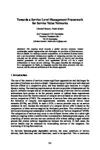
Proceeding to the pure idea of Mission Level Design, the question could come up whether there exist any software tools that support this design method? For our research on the topic to design an autonomous underwater vehicle within the DeepC project [5, 7], we have decided to use MLDesigner [4]. It conforms to many of the demanded features for model design on the one hand, and on the other to those of simulation, as well. Unfortunately, MLDesigner does not support configurable parameter sets yet. That’s why we have implemented two addional tools2 . Firstly, MLEditor for the mission handling and secondly MLVisor for the mission specific evaluation. Figure 1 shows the connection of the task to the tools and clarifies the design steps again. 2 As MLDesigner is only available for Linux, both tools were programmed at this platform with help of the QT library [1], too.
Figure 1. MLD design steps
2.1
MLDesigner
We are using MLDesigner for the modelling of the overall system model and for the simulation. It’s a hybrid simulation tool because it supports the simulation of different model approaches in one model. Thus, there exist basic primitives for different domains: time discrete, synchronous data flow, finite state machines and continuous time models. These are needed for a rapid design test. If all primitives are ready to use in a library, the modelling can be done simply by assembling the primitives. Additionally, its important to have the freedom to expand the feature set. MLDesigner enables the implementation of own primitives. Therefore, it has a build-in source editor and a very useful documentation. The primitives are implemented by the use of C++ templates. The modeler can define own data structures within the model. Above that MLDesigner offers basic visualization plots.
Modelling The modelling of the overall system model happens by taking primitives from the library and placing them into the model. Their inputs and outputs are linked by lines. The parameters of the system, the subsystem and the primitives are assigned next. The modeler labels them with tags which describe their type (#MP[#pt]#xxx3 , #SP[#pt]#yyy4 ). These labels are a MLEditor expansion and not a part of the original MLDesigner workflow. When the overall system model is finished so far, the modeler adds probs. These special primitives were written to put information into the simulation database (SDB). The probs are designed to work together with MLVisor. They will deposit the data for each project in an own SQL database during the simulation. Now, they are only configured by setting the needed information like database name or data stream name. At this state the model can’t be simulated, because all parameters are taged. Simulation All configured models are simulated in MLDesigners simulation mode. At this time, the output data gets written to the SDB. The database consists of three different types of tables: • INDEX TABLE name type id int mission int simulation int string date host string user string
• DESCRIPTION TABLE name type meaning id int automatic index object string name of data stream description string its description • tabels named like: name type id int names sting
Figure 2. MLDesinger
meaning automatic index misson number simulation number date, time host name user name
id object meaning automatic index names of data stream components (object.name)
The tables are filled with the simulated data values and the general data. Table 1 shows an excerpt from the SDB. The INDEX TABLE knows two simulation runs for different missions. For simulation run 319 two data streams called BATTERY and POSAUV are stored. Their value tables are 134 BATTERY and 134 POSAUV, because the simulation run 319 has the internal id 134. POSAUV consists of the subitems x, y, z, roll, pitch, yaw and time and can be identified as the AUV Position by the descirbtion in DESCRIPTION TABLE. 3 mission
parameter (pt{optional}: required plugin type for MLEditor; xxx: standard value) 4 system parameter (pt{optional}: plugin type; yyy: name)
INDEX TABLE id mission simulation 133 2 318 134 3 319 DESCRIPTION id object 1 POSAUV 2 BATTERY
host localhost localhost
user tvl tvl
date 30.06. 30.06.
TABLE describtion AUV Position battery charge
133 id 1 2 ...
PosAUV time x 0.0 1.0 0.1 1.0 ... ...
y 1.0 0.99 ...
134 id 1 2 ...
PosAUV time x 0.0 1.0 0.1 1.0 ... ...
y 0.0 0.0 ...
134 id 1 2 ...
BATTERY time 0.0 60.0 ...
z 1.0 1.01 ... z 0.0 0.0 ...
roll 0.0 0.0 ... roll 0.0 0.0 ...
pitch 0.0 0.0 ... pitch 0.0 0.01 ...
yaw 0.0 0.0 ... yaw 0.0 0.0 ...
battery 100.0 97.521
Table 1. Example from SDB
2.2
MLEditor
For the mission handling we have developed a special tool, called MLEditor. It is able to scan the MLDesigner models for parameter tags5 . For these it allows type dependent the definition of missions or the assignment of values. Configured overall models can be written. MLEditor presents the found parameters ordered in a model tree (see Figure 3). This has the advantage of a much better overview over the parameters and their connection to the model. It also ensures, that multiple parameters with the same name may exist. The presentation is ordered by type. For mission parameters the tool allows the creation of missions. Therefore all of them are editable in a table. If no value is assigned, the standard value will be used. To handle the different parameter data types6 , MLEditor uses a plugin system. With this, the input of the various data7 turns out to be easy. 5 This is easy, because MLDesigner uses a XML structure for the model files. 6 double, string, composed data structure, etc. 7 For our research we implemented a plugin for AUV mission plans. It allows the input of a mission with different manoeuvres like descent phase, maeanders or other path elements in 3D space. This plugin realizes a complex protocol and supports the user on inputing the numerous partial parameters. To improve the user’s convenience, the plugin additionally offers a preview.
Figure 3. MLEditor Expl id ... 17 18 ...
Names name ... high priority Sonar::range ...
Expl id 1 2 3 ...
MP ... a18 ... 100 . . . #MLESTD# ... 80 ... ...
Expl SP id . . . a17 1 ... 10
paramlist ... AUV/AFS/CS/SonarCtrl::priority AUV/AFS/Sonar::range ... ... ... ... ...
... ...
Table 2. Example from PDB
The complete parameter data is stored in a parameter database (PDB)8 . Therefore, three database tables are used for each project. The first is named Project Names and hold an id, the name and the complete model path for each parameter. Project MP, the second table, consists of the values for all mission parameters. The table columns are labeled like ’a17’. This means, that this is the column for the parameter whose id is 17 in Project Names. The first row is filled with the standard values and the remaining ones are used to store the missions. At last, the third table Project SP holds the system and design parameters. It is organized identically to Project MP with the only difference, that these parameters have only one value. Table 2 presents an example PDB. For project Expl one mission (Sonar::range) and one system parameter (priority high) are shown. The mission parameter has the standard value of 100. In mission 1 this will be used, whereas for mission 2 the value changes to 80. The system parameter priority high has the value of 10 for all simulations; 8 Note:
This is not identical with the simulation database (SDB).
When reopening a project, the contents of the PDB is synchronized with the overall system model.
2.3
visualization. For the user such a plugin is a window within the tool. Typical data views are already programmed. • 1D-LED-Plugin: can be used to visualize binary data. The plugin presents a table of settable size, where the fields can be filled with named LEDs. The LED color changes from green to red in dependence of the value. For non-binary data a threshold is used for the transformation to binary type.
MLVisor
• 1D-Bar-Plugin: presents one or more small bars that show the current value between minimum and maximum (see Figure 6). An alarm level is supported on which the color of the bar changes to a settable color. The plugin shows the current value as tooltip.
Figure 4. MLVisor
MLVisor (Figure 4), our visualization and evaluation tool, helps us to handle the huge amount of simulation output data. The general information are read form the SDB by the application so that the user can select a simulation run. The presentation is ordered by mission and simulation number. For the selected mission all data streams are acquired and will be presented to the user while choosing data for displaying (see Figure 5).
Figure 6. 1D-Bar-Plugin
• 2D-Plugin: is used for all 2 dimensional plotting, such as value over time or value over value. It is based on the Qwt library [2] and therefore supports different styles, colors, and a legend. The plugin allows it to save the contents to a picture.
Figure 5. Assignmet widget for data streams to plugin
The visualization itself is realized by plugins. There exist two types of plugins for MLVisor. The first one allows the data preprocessing. It creates new data streams as a function of one or more input streams9 . For this reason, they quasi are invisible, only their output streams appear in the selection list. The second type of plugins does the real 9 For
example, we implemented a plugin, that computes the histogram of a data stream.
Figure 7. 2D-Plugin
• 3D-Plugin: enables the visualization of high dimensional data in a virtual environment. The plugin defines the world and may be filled with objects which are coupled to data sets (3D or 6D). For the objects’ representation the user can choose between basic primitives (cone, cube, cylinder, sphere) or own 3D-models (*.vrml or *.iv). Figure 8 shows a vrml model of an AUV used by the plugin. Three different camera styles are selectable (free, view object, chase camera with own dynamics). Additionally, it is possible to plot the traces of the object positions. The plugin was implemented with the help of the Coin library [3] which is an implementation of the SGI Open Inventor API.
several clicks. Mission specific means, that such a configuration can be used for different simulation runs of the same mission, or possibly even for other missions. Additionally, MLVisor contains the basic features of managing the missions in the SDB.
3
Conclusion
We have presented the idea of Mission Level Design, which means system design test for defined missions by the use of simulation. Furthermore, we have shown how this concept can be implemented in a framework of software tools to enable the practical usage. Therefore, we have introduced MLEditor and MLVisor as add-ons for MLDesigner. While MLEditor handels the usage of missions and system parameters, MLVisor allows the mission specific visualisation and evaluation.
References [1] QT Library, Trolltech: http://www.trolltech.com [2] Qwt Library: http://qwt.sourceforge.net [3] Coin Library: http://www.coin3d.org [4] MLDesigner: http://www.mldesigner.com [5] DeepC project: http://www.deepc-auv.de Figure 8. 3D-Plugin
• semi-automatic evaluation: This plugin tests the violation of system or design parameters. Therefore it can read the values from the PDB. Only if a violation occurs the visualisation is done. This just-in-case presentation is not realizable by preprocessing plugins. Furthermore, it is possible to implement own plugins for special visualization tasks10 . One of the design goals of MLVisor was it to have a synchronous visualization of asynchronous data. That’s why, MLVisor possesses a timeline and most of the plugins are able to be set in an animation mode. In this mode they synchronize their presentation to the global time. For example, the 2D plugin fades in a line symbolizing the time. Others, as the 3D plugin show a real animation. So, the 3D objects are moving in the 3D world. To smooth the animation, linear interpolation is used. The animation velocity is settable to adopt different time scales. Another main feature of MLVisor is its ability to store the plugin configuration. The user can get mission specific evaluation interfaces just by putting them together by 10 For example, we have programmed a artifical horizon. This aeronautic instrument shows an aircraft’s attitude by showing the pitch and roll in relation to the ground. We use it for a better understanding of the AUV’s manouevres.
[6] Gunar Schorcht: Entwurf integrierter Mobilkommunikationssysteme, Logos Verlag 2001 [7] Liebezeit, Th.; Zerbe, V.: Mission Level Design for Autonomous Underwater Vehicles. In: Proc.-CD First International NAISO Congress on Autonomous Intelligent Systems (ICAIS’2002) Geeloang, Australia Feb. 2002 auf Missionsebene