A Computationally Efficient Current Controller for Simultaneous Injection of both Positive and Negative Sequences Zunaib Ali*, Nicholas Chritofides*, Lenos Hadjidemetriou**, Elias Kyriakides** *Frederick University Electrical Engineering Department 7 Y. Frederickou Street, Pallouriotissa Nicosia, Cyprus
[email protected]
**University of Cyprus KIOS Research and Innovation Center of Excellence P.O. Box 20537 CY-1678 Nicosia, Cyprus
[email protected]
Acknowledgements The authors Zunaib Ali and Nicholas Christofides are highly grateful to the Erasmus Mundus Leaders (EM-Leaders) mobility program for providing PhD fellowship. The authors Lenos Hadjidemetriou and Elias Kyriakides are supported by the Research Promotion Foundation (RPF, Cyprus, Project KOINA/SOLAR-ERA.NET/1215/06), by the Ministry of National Infrastructure Energy and Water (Israel) and the SOLAR-ERA.NET (European Union’s Seventh Framework Programme).
Keywords «Current Controller», «Computational Complexity», «Grid Disturbances», «Renewable Energy Integration», «Grid Side Converter Control »
Abstract Reducing the required processing time of current controllers used in grid side converter (GSC) of renewable energy systems (RES) allows to optimize the limited processing resources and at the same time minimize the cost of the processors required. In addition, the transient behavior of these controllers must be fast and with low overshoot for the GSC to support the grid during off-nominal grid conditions and according to the grid code requirements imposed. For a converter to respond accordingly, the injection of both positive and negative sequences of fundamental current under off-nominal grid conditions is necessary. The work presents a GSC current controller that meets all modern grid requirements expected. It has been developed by introducing two modifications to an existing current controller. Experiments and simulations have been performed to validate the operation of the proposed current controller in terms of complexity and performance. Consequently, the new current controller requires 22% less processing time and can achieve a faster and more accurate response in order to meet modern grid code requirements under off-nominal conditions.
1. Introduction The ongoing high level integration of renewable energy systems (RES), in particular photovoltaic (PV) and wind energy, to the utility grid may give rise to problems related to grid stability and power quality. Advanced grid regulations are therefore imposed to ensure the accurate and reliable operation of grid connected RES in the events of grid faults and other off-nominal grid conditions [1-4]. These regulations involve the injection of high quality currents from RES under normal, harmonically distorted, and unbalanced grid conditions, grid frequency variations and other disturbances. Furthermore, RES should remain interconnected and provide reactive power support under grid faults thereby entering the Fault Ride Through (FRT) mode [5-8]. During FRT mode, the injection of both positive and negative sequence currents may be required for supporting the grid under abnormal grid scenarios, thereby enhancing the stability of the power system. Energy generated from RES is efficiently transferred to the utility grid via power electronic based Grid Side Converter (GSC) [9, 10]. Hence for meeting the modern grid regulations, appropriate control techniques with improved performance and reduced complexity are needed for GSC [5, 7]. The GSC controller consists of two control loops, the inner current controller
and the outer active/reactive power (PQ) controller [10-12]. The PQ controller generates the current references corresponding to desired active/reactive power injection. Consequently, the current controller is used to inject the reference currents into the utility grid. The performance accuracy of RES is critical under abnormal grid conditions such as grid voltage faults, frequency variations, harmonic distortion and phase offsets. Therefore, the design of PQ and current controllers must be considered properly for accurate and reliable operation of RES under faults and other disturbances. The control of GSC can be implemented either in stationary reference frame or in synchronous reference frame (SRF) [13, 14]. However, the control of GSC in SRF is more straightforward and all the controlled variables become DC quantities, thereby easily controlled in a decoupled way using low order controllers. In literature, many currents controllers have been presented dealing with aforementioned issues. The SRF based current controller [11]-[12] is the conventional control technique utilizing two PI controllers ) for generation of voltage references. However, when this current and positive synchronous frame ( controller is exposed to unbalanced faults, it cannot perform significantly due to the existence of double frequency oscillations on transformed voltage/current vectors resulting from the presence of negative sequence grid voltage. The undesired 2 oscillations mainly affect the performance of the positive sequence PI controller. The dual SRF (DSRF) current controllers proposed in [15]-[16] mitigate the problem of these oscillations by introducing filtering techniques. The DSRF controller is developed by combining two conventional SRF controllers respectively operating in fundamental positive and negative frames with an additional filter. However, the additional SRF controller and filter increase the computational complexity and result in slower dynamic response due to the presence of the filter in the control loop. For improving the dynamic response of DSRF and to avoid use of filter in the control path, an enhanced decoupled dual SRF (EDDSRF) current controller is proposed in [17]. In EDDSRF controller, the undesired 2 oscillations are mitigated by estimating their magnitude and subtracting it from the positive and negative currents using a novel cross-decoupling network. The decoupling network allows the injection of both positive and negative current sequences free of any oscillations. This however increases the computational complexity significantly due to increased Park’s transformations. The computational complexity, however, is an important factor in real time implementation of control algorithm, since current digital signal processors employed in GSC have limited processing resources [18]. Furthermore, a higher control effort is required by EDDSRF controller, because the essential voltage feedforward terms are not used [19]. The effect of grid voltage harmonic distortion is not considered by the controllers mentioned above. An equivalent version of conventional SRF controller is proposed in [20], where a Proportional-Resonant (PR) controller is used instead of PI controller, but in a similar manner it cannot work under abnormal grid scenarios. Few interesting techniques are discussed in [21-23], where a combination of PR and PI controllers are used to achieve accurate response under unbalanced grid conditions. Furthermore, in [24] multiple Resonant (R) controllers are being used in fundamental positive reference frame for mitigating the effect of harmonic distortion, in addition to positive sequence injection. However, in this case the unbalanced grid conditions are not considered and the controller is able to inject only positive sequence of current. In [25], PR controller is used in combination with integral controllers for enabling the accurate injection of current under grid voltage unbalance and harmonic distortion. Nevertheless, it is worth mentioning that the PR controller does not allow the use of voltage feedforward terms, which however, imposes an undesired higher control effort on the current controller [19]. Furthermore, some current controllers consisting of multiple SRFs are proposed in [26-28] for compensating the effect of grid harmonic distortion and allows the injection of high quality current. These controllers are simple in structure but do not consider the effect of unbalanced of grid voltage. In addition, all the aforementioned controllers can only inject the positive sequence of current, except EDDSRF current controller, that allows simultaneous injection of both the sequences but at high computational cost. For mitigating the undesired effect of both the harmonic distortion and unbalanced faults an interesting technique is proposed in [19]. The technique uses multiple SRF in combination with conventional SRF current controller for enabling accurate injection of fundamental pure sinusoidal positive or negative current sequences. The aforementioned controller cannot inject both the fundamental positive and negative sequences of current simultaneously. An important thing to mention is that under grid faults, the injection of positive sequence current can provide voltage and frequency support to the grid while the negative sequence currents can minimize the unbalances caused by the grid faults.
In this paper two interesting modifications are proposed to the existing controller of [19] for enabling the accurate injection of both sequences of current simultaneously with reduced computational cost. In the first modification, the reference for negative sequence is added to the error between the fundamental positive sequence reference and the measured signal. Furthermore, a decoupling network is used for eliminating the effect of double frequency oscillation for allowing accurate operation of positive sequence controller. In contrast to [17], the computational complexity of the first proposed modification (referred to as modification 1) is less because of the reduced number of Park’s transformations and the elimination of the additional SRF controller for negative sequence. The Modification 1 was subsequently investigated and an even better performance was achieved. The second modification (referred to as modification 2) presents even lower computational complexity and improved performance compared to modification 1 and controller in [17]. Section 2 of the paper discusses the capabilities of an existing current controller. The modifications proposed are analyzed and presented in section 3. The computational complexity analysis is discussed in section 4. Section 5 presents the simulation and experimental verification of proposed current controllers.
2. Existing Current Controller The current controller in [19] utilizes the conventional SRF technique rotated with either positive or negative speed for injecting either positive or negative current sequence, respectively. In addition to the conventional part that can work only under balanced grid conditions, an unbalance compensation module (UCM) is introduced in [19] for compensating the effect of unbalanced grid voltage. Furthermore, for enabling the injection of high quality current under harmonic distortion, the harmonic compensation module (HCM) is implemented in multiple SRF frames, as shown in Fig. 1 (where T and T are the transformation matrices). This current controller cannot inject both the fundamental positive and negative sequences of current simultaneously, which is an important flexibility that can enable a more proper grid support under faults and disturbances. The simultaneous injection is enabled by controller in [17], but it’s computational complexity is very high.
iαβ
−
Tdq+1
+1 idq
+ iαβ − ref
+
−
Δ i d+
PI
ωLf
id+−1 ref
vd +
−
T −1 dq
+
ωLf
−
PI iq − ref+ Δiq+
+
vαβ
Tdq+1
k −1 s
Tdq−5
k −5 s
Tdq+5
+
Tdq+5
k +5 s
Tdq−5
+
Tdq−7
k −7 s
Tdq+7
+
Tdq+7
k +7 s
Tdq−7
+
idq−1 +
T
−
+1 iαβ − ref
*−1 + vαβ
+
+ +
−
−1 dq − ref
i
Harmonic Compensation Module
Fig. 1: Existing current controller of [18].
+
−
ωLf
−1 idq − ref
LPF
−
iq+−1ref+ Δiq+
Tdq−1
+
ωLf
+
PI
+1* vαβ
v q+
Unbalance Compensation Module
iαβ
vαβ
−
vd+
PI
−1 Δidq
* vαβ
**hh
+1' + idq
−
+2 dq
++
Tdq−1
Tdq+1
+1*
vq
Unbalance Compensation Module
Δiαβ
+ + Δ id
iαβ
dq
Δiαβ
id − ref
αβ
++
T
k−1 s
T
Tdq−5
k−5 s
Tdq+5
+
+5 Tdq
k+5 s
Tdq−5
+
−7 dq
T
k−7 s
T
+
Tdq+7
k+7 s
Tdq−7
+
−1 dq
+1 dq
+7 dq
* vαβ
*−1 + vαβ
*h vαβ
Harmonic Compensation Module
Fig. 2: Proposed modification 1 (Type A current controller)
3. Proposed Current Controllers In this section, the proposed modifications (1 and 2) for enabling the simultaneous injection of both the positive and negative sequences of current are discussed in detail.
3.1 Modification 1 (hereafter referred to as Type A Controller) As mentioned earlier, the existing current controller in [19] can only inject one sequence of current at a time. Hence, modification 1 is being proposed to enable the simultaneous injection of both the sequences (positive and negative) and resulting controller is referred as Type A controller. The unbalance compensation module of existing current controller is utilized for injecting negative sequence in addition to compensation of unbalanced faults. The stepwise modification is as follows: i. The reference for negative sequence current is added to the error between the fundamental positive sequence reference and the measured signal, as shown in Fig. 2. ii. Introduction of decoupling network: The injection of negative sequence will result in 2 oscillations on positive sequence, which are subsequently decoupled to enable accurate operation of positive sequence controller. After step (i), the oscillations occur on positive sequence current because the actual measured signal (containing both positive negative sequences) is being transformed to SRF with + speed. Therefore, undesired oscillations are decoupled using a decoupling network. In contrast, no oscillations are observed on negative sequence -axis currents, due to the fact that the transformation (under – speed) is provided with error signal and not the actual measured signal as in the positive sequence case. The computational complexity of controller with proposed modification 1 is less due to reduced decoupling cell and cross coupling/feedforward terms for negative injection, compared to controller in [17]. The performance of both controllers remains similar.
3.2 Modification 2 (hereafter referred to as Type B Controller) The computational complexity can further be reduced by introducing a second modification, which also improves the controllers’ performance (lower oscillation/overshoot during disturbances). The details of modification 2 are listed below: i. From modification 1, it was evident that feeding the error signals before frame transformation does not give rise to oscillations on other frames. ii. Hence, a similar modification (feeding of error before frame transformation) was introduced to the positive injection part of controller, as shown in Fig. 3. This eliminates the use of decoupling network. iii. The only problem in feeding the SRF with error is how to implement the cross-coupling terms necessary for control implementation, since the cross coupling requires the measured currents instead of the error signal. The measured signals are calculated by a mathematical approach where the current error signal is subtracted from the reference current, as shown in Fig. 3. The modification 2 (referred to as Type B controller) has significantly reduced the computational complexity due to complete elimination of decoupling networks as opposed to the one employed in [17] and modification 1. Furthermore, the performance of Type B controller is enhanced in terms of lower overshoot and fast dynamic response compared to modification 1 and is comparable to the controller proposed in [17]. Hence using proposed modification 2, the positive and negative sequences of currents are injected accurately with reduced complexity and improved performance.
4. Computational Complexity Analysis The computational complexity analysis of Type A, Type B and current controllers of [19] and [17] are shown in Table I. The computational analysis considered the number of algebraic manipulations required and the processing time from MATLAB’s profiler report. The controller in [17] was used as reference for the comparisons presented. The lower computational complexity and processing time of proposed Type A and Type B current controllers compared to controller in [17] are verified from Table I. Type B current controller requires 22% less processing time compared to controller in [17]. The computational complexity of Type B current controller is equal to controller in [19] but it is worth mentioning that the Type B controller can inject both sequences of current simultaneously as opposed to controller of [19] which allows injection of one sequence at a time. Hence, compared to [19] the performance capabilities of Type B current controller are enhanced. Between Type A and Type B, the Type B has lower complexity and improved performance, as observed by the lower overshoot and less oscillations.
αβ
Δiαβ
++
− +
Tdq+1
i
Δi
vd+
PI
+
−
ωLf
Tdq−1
+
ωLf
Δ iq+
+
PI
Δiαβ
dq
αβ
++
k −1 s
T
Tdq−5
k−5 s
Tdq+5
+
Tdq+5
k+5 s
Tdq−5
+
Tdq−7
k−7 s
Tdq+7
+
Tdq+7
k+7 s
Tdq−7
+
+ +
+1* vαβ
v q+
T −1 dq
iαβ i
Δ i d+
Unbalance Compensation Module
+
−
−1 dq − ref
id+1'
+ dq
−1 iαβ − ref
+1 iαβ − ref
+1' q
Vabc (pu)
iαβ
−
+1 dq
* vαβ
Iabc (A)
dq
+
*−1 + vαβ
I dq (A)
idq+1− ref
idq+1−ref
*h vαβ
Harmonic Compensation Module
Fig. 3: Proposed modification 2 (Type B current controller).
Fig. 4: Simultaneous injection using Type A current controller.
Table I: Complexity Analysis for Three Controllers in terms of required Multiplications (×), Additions (+) and Subtractions (−) in each control loop.
Complexity Analysis
Current Controller
[Modification 1]
[Modification 2]
Ref.[19]
PI Controller
2
2
2
4
blocks
14
13
13
16
10 Needed Needed
10 Needed Needed
10 Needed Needed
10 Not Needed Not Needed
Needed for one frame
Not Needed
Not Applicable
Needed for both frames
(×): 104; (+): 39; (−): 17; Total: 160 (113.47%)
(×): 94; (+): 34; (−): 13; Total: 141 (100%)
(×): 94; (+): 34; (−): 13; Total: 141 (100%)
(×): 124; (+): 48; (−): 18; Total: 194 (137.58%)
3.96 (108%)
3.65 (100%)
3.65 (100%)
4.46 (122%)
Positive and/or Negative
Positive and/or Negative
Positive
Positive and/or Negative
Integral Controllers Feed-forward Cross-Coupling Decoupling for Simultaneous Injection Total mathematical operations in each loop
Processing time for each loop (MATLAB profiler report) Current Injection Performance Capabilities
Ref.[17]
Note:- Harmonic Compensation Module (HCM), Unbalance Compensation Module (UBM), Decouple Network (DN); Each requires: 6 Multiplications (×) + 1 Addition (+) +1 Subtraction (−); Each PI requires: 2 (×) + 2(+); Cross Coupling: 2(×) + 1(+); Feedforward: 1(+); Each I require 1 (×) + 1(+)
5. Results and Discussion The current injection capability of proposed current controllers is validated through simulation and experimental results.
5.1 Simulation Results The performance of proposed modifications is validated through simulation results performed in MATLAB. Initially, the results for modification 1 and 2 are presented separately. Following this a comparison is also presented between the two showing the improved performance of proposed modification 2 compared to that of modification 1. The tuning procedure is common to all the controllers discussed in this paper and is presented in appendix. The -5th and +7th voltage harmonic is set to 0.03pu and 0.02pu (similar for all cases). and The results for proposed modification 1 are depicted in Fig. 4. With zero initial value, at 0.4s are subjected to a step change of 4.5A and 2A, respectively. Similarly, at 0.55s and are changed to 2 . An unbalanced fault occurs at 0.65s. The proposed modification 1 allows fast and accurate injection of both the sequences simultaneously by utilizing the existing unbalance module of [19]. The proposed modification can be compared to enhanced dual SRF frame current controller [17] in terms of computational complexity, since both the controllers can inject simultaneous current and also
the performance in terms of current injection is comparable (as shown in Fig. 5). However, the computational complexity of controller with proposed modification 1 is less compared to [17] due to reduced decoupling cell and cross coupling/feedforward terms for negative injection, as can be seen in Table I. The results for modification 2 are shown in Fig. 6. All the fundamental sequence values, harmonic conditions and time of activation are similar to previous results. By proposed modification 2, the computational complexity is further reduced and in addition, the performance is also improved with less oscillations/overshoots compared to modification 1. A comparison of proposed modification 1 (legends (injected denoted by ‘A’) and modification 2 (legends denoted by ‘B”) is presented in Fig. 7, with at 0.4s) and (injected at 0.55s). Following this, an unbalance fault is activated at 0.65s. It can be seen by the zoomed inset that the new Type B current controller improves the quality of injected currents and has more accurate response under all the variation points.
Fig. 5: Simultaneous injection comparison between Type A and ED.
Fig. 6: Simultaneous injection using Type B current controller.
Fig. 7: Simultaneous injection comparison between Type A and Type B.
Fig. 8: Simultaneous injection comparison between Type B and ED.
Furthermore, the type B controller is also compared with [17] in Fig. 8 with variation time and current values similar to previous cases. The current controller of [17] is denoted by ‘ED”. It can be seen that the injection capability of proposed Type B current controller is equivalent to the one in [17], but using
proposed Type B current controller the injection is enabled with the requirement of comparatively 37.58% less mathematical operations and 22% less processing time, according to Table I.
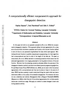
5.2 Experimental Verifications The performance of proposed current controllers is also validated through experimental results. The experimental setup employed in the laboratory consists of different modules, as shown in Fig. 9 and is according to schematic in Fig. 10. The same schematic of Fig. 10 is also employed for the purpose of simulation results. The experimental setup however consists of few differences as opposed to the simulation setup. More specifically, the inverter employed in simulation setup is a three-phase 5 inverter and the voltage at PCC is set equal to 230 V. The corresponding current limit for 5 inverter is 10.25 . The experimental setup however, considers a voltage of 132.8 V at PCC due to the presence of 5 y/D transformer necessary for grid isolation. In addition, the three-phase inverter employed is 1.8 kVA with maximum current limit of 6.5 . For the experimental verification, the current controllers along with the necessary GSC control system is implemented using a dSPACE DS-1104 DSP board along with dSPACE ControlDesk and Matlab/Simulink Real Time Interface. The inverter model used as GSC is a SEMIKRON Semiteach (B6U+E1C1F+B6CI). The ELEKTRO-AUTOMATIK (EA-PS9750-20) DC power supply was used to emulate the renewable energy DC source. The sampling rate for both simulation and experimental results was 4 kHz. The current controllers are tuned using closed-loop system of Fig. 11 and tuning parameters are similar for both experimental and simulation results. More details about tuning procedure can be found in Appendix.
D
Rf =0.14 Ω
PCC
dSPACE DS1104 DSP board
Pref / VDC Qref / Vgrid
Lf =4.93 mHVabc − GSC
Vdq±1
PQ Controller with FRT capability
DC
Cf ∆ =7.8μF n
PLL
θ
I ref
AC
GSC Semikron
PLL
B6U+E1C1F+B6C1
Current Controller
- VDC +
L grid
y
LC Filter
Vabc − m I abc − m
Power Grid
V abc − ref
DC Power Supply Emulating RES production (EA-PS 9750-20)
PWM Modulation
Fig. 10: Schematic of grid connected RES system. GPI (s )
i ref + −
i
Fig. 9: A Photo of experimental setup.
5.2.1
kp +
1 Ti s
v ff +−
Gdel (s )
1 1 + Td s
v +−
G f (s )
1 R f + Lf s
Fig. 11: Current controller closed-loop control system, is voltage feedforward and is the grid voltage.
Experimental Validation: Case Study I
The Type A and B current controllers are experimentally validated through two sets of experiments. In both case studies, the positive sequence and axis currents are respectively injected according to desired active and reactive powers (1200 W and 0 VAR for case I). The first case study analyzes and compares the responses of Type A and B current controllers when a step change of −2 occurs in . The initial value of negative sequence currents is set to zero, consequently both the controllers are injecting three-phase balanced sinusoidal currents. The inverter continues to inject is changed from zero to −2 (marked in Fig. 12). positive sequence symmetrical currents until At this point, the injected three-phase current becomes unbalanced and asymmetrical due to the negative sequence current injection. The improved quality of current injected by Type B current controller can be seen from which in case of Type A current controller suffers from more distortion. Overall both the proposed current controllers offer similar performance, but it is worth mentioning that the Type B current controller enables accurate injection with less computational complexity.
Type A
Type B
id−1 Injection
ia [5 A/div] ib [5 A/div]
id−−1 ref
id−1 Injection
ic [5 A/div]
ia [5 A/div] ib [5 A/div]
id−−1 ref
[2 A/div]
ic [5 A/div]
[2 A/div]
t [10 ms/div]
t [10 ms/div]
Fig. 12: Case I: Experimental results validating the simultaneous injection of both current sequences for Type A and Type B. =0 −2 , = 0, = 4 (1200 ), = 0 (0 ).
5.2.2
Experimental Validation: Case Study II
The second case study investigates the two current controllers when active power of 1000 W is commanded by providing the d-axis reference of positive sequence current and later, the q-axis negative sequence is injected. Until t=26.425 sec (for Type A) and t=0.20 sec (for Type B), both the controllers inject = 3.45 . However, at t=26.425 sec and 0.20 sec, the is subjected to a step change of +2 A and corresponding responses with unbalanced current injections are shown in Fig. 13. Both the proposed current controllers accurately inject the negative and positive sequences of current simultaneously with less computational complexity as compared to existing EDDSRF controller. Both Type A and Type B achieve equivalent performance but the complexity of Type B is lower than Type A. sequence Operating Positive metrica l Typesym Acurrents Scenarios
Type A
sequence Operating Positive Typesymcurrents Ametrica l Scenarios
Positive sequence and start of negative sequence inje ction
Phases
a
b
c
Positive sequence and start of negative sequence injection
Type B
Fig. 13: Case II: Experimental results validating the operation of both Type A and Type B current controller for simultaneous = 0, =0 2 , = 3.45 (1000 ), = 0 (0 ). current injection.
6. Conclusion The proposed modifications enable the injection of both sequences of current simultaneously with reduced computational complexity without compromising the quality of current. The decrease in processing resources (as listed in Table I) has a positive impact and provides greater flexibility to GSC manufacturers. Between Type A and B, the Type B controller is considered a better candidate for fast and accurate injection of current in grid connected RES.
7. Appendix 7.1 Tuning of current controller The design of current controller mainly depends on the proper tuning of PI and I controllers used within the control structure. Since, the dynamics of PI controller employed for injection of fundamental positive sequence are not affected by the addition of HCM and UCM, both PI and I controllers can be tuned separately. Consequently, the PI part of current controller is tuned first. The tuning of PI controller requires the transformation of current controller to corresponding closed-loop control system as shown ( ), transfer function in Fig. 11. The closed-loop system consists of a PI controller transfer function ( ) for incorporating the delays caused by components within control path and the LCL filter ( ), represents the total control path delay, which is the summation transfer function ( ). In of delay caused due to PWM generator (0.5 ), delay due to the computation devices, delay due to the sampling rate and any other delays ( ≈ (0.5) ). Where denotes the sampling period used for GSC controller. The LCL filter transfer function ( ) can be approximated with the transfer function of simple L filter according [12], as shown in Fig. 11, where is the sum of two LCL filter inductances is their combined resistance. and equal By combining all the three transfer functions according to Fig. 11 and by setting up the term to ⁄ , the closed loop transfer function can be simplified as (1). Where, denotes the current injected represents the reference current to be generated by the PQ controller. by the GSC and +1 ( )=
1
1 1+
= 1+
+1
1
1+
1 1+
1
=
+
1
+
1
(1)
1+
The transfer function in (1) represents a second order system and by selecting the value of damping coefficient ζ=0.707 (optimal value), the value of PI tuning parameters can be designed according to (2). =
and
=
(2)
The value of used in this paper is 2 and corresponding values of and are 5 and 1⁄800 respectively. The integral controllers in HCM and UCM can be tuned according to disturbance dynamics [19]. The I controllers in HCM can be tuned for relatively lower gain (200), since grid harmonics present slower dynamic response. Whereas, the UCM I controllers are tuned for higher gain (400) due to faster dynamic response of faults.
References [1] "IEEE Standard for Interconnecting Distributed Resources with Electric Power Systems," IEEE Std 15472003, pp. 1-28, 2003. [2] S. Yang, Q. Lei, F. Z. Peng, and Z. Qian, "A robust control scheme for grid-connected voltage-source inverters," IEEE Transactions on Industrial Electronics, vol. 58, no. 1, pp. 202-212, 2011. [3] F. Blaabjerg, M. Liserre, and K. Ma, "Power electronics converters for wind turbine systems," IEEE Transactions on Industry Applications, vol. 48, no. 2, pp. 708-719, 2012. [4] F. Iov, A. D. Hansen, P. E. Sørensen, and N. A. Cutululis, "Mapping of grid faults and grid codes," Risø National Laboratory8755036228, 2007. [5] L. Hadjidemetriou, P. Demetriou, and E. Kyriakides, "Investigation of different Fault Ride Through strategies for renewable energy sources," in PowerTech, 2015 IEEE Eindhoven, 2015, pp. 1-6. [6] P. Rodr, guez, A. Timbus, R. Teodorescu, M. Liserre, and F. Blaabjerg, "Reactive Power Control for Improving Wind Turbine System Behavior Under Grid Faults," IEEE Transactions on Power Electronics, vol. 24, no. 7, pp. 1798-1801, 2009.
[7] P. Rodriguez, A. V. Timbus, R. Teodorescu, M. Liserre, and F. Blaabjerg, "Flexible active power control of distributed power generation systems during grid faults," IEEE Transactions on Industrial Electronics, vol. 54, no. 5, pp. 2583-2592, 2007. [8] M. Tsili and S. Papathanassiou, "A review of grid code technical requirements for wind farms," IET Renewable Power Generation, vol. 3, no. 3, pp. 308-332, 2009. [9] F. Blaabjerg, C. Zhe, and S. B. Kjaer, "Power electronics as efficient interface in dispersed power generation systems," IEEE Transactions on Power Electronics, vol. 19, no. 5, pp. 1184-1194, 2004. [10] Z. Chen, J. M. Guerrero, and F. Blaabjerg, "A Review of the State of the Art of Power Electronics for Wind Turbines," IEEE Transactions on Power Electronics, vol. 24, no. 8, pp. 1859-1875, 2009. [11] F. Blaabjerg, R. Teodorescu, M. Liserre, and A. V. Timbus, "Overview of Control and Grid Synchronization for Distributed Power Generation Systems," IEEE Transactions on Industrial Electronics, vol. 53, no. 5, pp. 1398-1409, 2006. [12] M. L. R. Teodorescu, and P. Rodriguez, Grid Converters for Photovoltaic and Wind Power Systems, chapter 8. Hoboken, NJ, USA: Wiley-IEEE Press, 2011. [13] P. Rodriguez, A. Luna, R. S. M. Aguilar, I. Etxeberria-Otadui, R. Teodorescu, and F. Blaabjerg, "A Stationary Reference Frame Grid Synchronization System for Three-Phase Grid-Connected Power Converters Under Adverse Grid Conditions," IEEE Transactions on Power Electronics, vol. 27, no. 1, pp. 99-112, 2012. [14] Z. Ali, N. Christofides, L. Hadjidemetriou, and E. Kyriakides, "Performance Enhancement of MAF based PLL with Phase Error Compensation in the Pre-Filtering Stage " in Proceedings IEEE PowerTech, Manchester, 2017, pp. 1-6. [15] S. Yongsug and T. A. Lipo, "Control scheme in hybrid synchronous stationary frame for PWM AC/DC converter under generalized unbalanced operating conditions," IEEE Transactions on Industry Applications, vol. 42, no. 3, pp. 825-835, 2006. [16] S. Hong-Seok and N. Kwanghee, "Dual current control scheme for PWM converter under unbalanced input voltage conditions," IEEE Transactions on Industrial Electronics, vol. 46, no. 5, pp. 953-959, 1999. [17] M. Reyes, P. Rodriguez, S. Vazquez, A. Luna, R. Teodorescu, and J. M. Carrasco, "Enhanced Decoupled Double Synchronous Reference Frame Current Controller for Unbalanced Grid-Voltage Conditions," IEEE Transactions on Power Electronics, vol. 27, no. 9, pp. 3934-3943, 2012. [18] R. Teodorescu, F. Blaabjerg, and M. Liserre, "Proportional-resonant controllers. A new breed of controllers suitable for grid-connected voltage-source converters," in OPTIM 2004, Brasov, Romania, 2004. [19] L. Hadjidemetriou, E. Kyriakides, and F. Blaabjerg, "A grid side converter current controller for accurate current injection under normal and fault ride through operation," in Industrial Electronics Society, IECON 2013 - 39th Annual Conference of the IEEE, 2013, pp. 1454-1459. [20] D. N. Zmood and D. G. Holmes, "Stationary frame current regulation of PWM inverters with zero steadystate error," IEEE Transactions on Power Electronics, vol. 18, no. 3, pp. 814-822, 2003. [21] J. Hu, Y. He, L. Xu, and B. W. Williams, "Improved Control of DFIG Systems During Network Unbalance Using PI&R Current Regulators," IEEE Transactions on Industrial Electronics, vol. 56, no. 2, pp. 439-451, 2009. [22] C. Wessels, N. Hoffmann, M. Molinas, and F. W. Fuchs, "StatCom control at wind farms with fixed-speed induction generators under asymmetrical grid faults," IEEE Transactions on Industrial Electronics, vol. 60, no. 7, pp. 2864-2873, 2013. [23] Z. Ali, N. Christofides, and A. Polycarpou, "Performance Enhanced RES Current Controller with Reduced Computational Complexity," in Proceedings IEEE MPS, Romania, 2017, pp. 1-6. [24] M. Liserre, R. Teodorescu, and F. Blaabjerg, "Multiple harmonics control for three-phase grid converter systems with the use of PI-RES current controller in a rotating frame," IEEE Transactions on Power Electronics, vol. 21, no. 3, pp. 836-841, 2006. [25] Z. Ali, N. Christofides, L. Hadjidemetriou, and E. Kyriakides, "An Advanced Current Controller with Reduced Complexity and Improved Performance under Abnormal Grid Conditions " in Proceedings IEEE PowerTech, Manchester, 2017, pp. 1-6. [26] M. J. Newman, D. N. Zmood, and D. G. Holmes, "Stationary frame harmonic reference generation for active filter systems," IEEE Transactions on Industry Applications, vol. 38, no. 6, pp. 1591-1599, 2002. [27] T. L. Lee, J. C. Li, and P. T. Cheng, "Discrete Frequency Tuning Active Filter for Power System Harmonics," IEEE Transactions on Power Electronics, vol. 24, no. 5, pp. 1209-1217, 2009. [28] V. T. Phan and H. H. Lee, "Control Strategy for Harmonic Elimination in Stand-Alone DFIG Applications With Nonlinear Loads," IEEE Transactions on Power Electronics, vol. 26, no. 9, pp. 2662-2675, 2011.