A Computer Code for the Simulation of X-ray Imaging Systems Seong Kyu Ahn, Gyuseong Cho, Yong Ki Chi, Ho Kyung Kim and Moosung Jae
Abstract—A computer code was developed to simulate
an X-ray imaging system, which is composed in X-ray source, object and detection parts. The physical principles are the X-ray attenuation law and the detecting probability based on deterministic methods. In the part of an X-ray source, it uses a source spectrum and prepares corresponding attenuation coefficients for object materials. A computer-aided drawing (CAD)-formatted file is used as the object geometry to make it convenient to describe complex 3-D object components. The number of pixel and the size of detector are variable in the part of a detector. Transmission images can be simulated with various X-ray energies, including spectrum and various system geometries. The simulation code has its graphic user interface (GUI), which makes it easy to perform selection of simulation parameters. I. INTRODUCTION imaging systems have been widely used in the fields Xof- medical and industrial application. Great efforts also RAY
have been made for improving of detection systems and optimum design conditions of operating components, e.g., Xray sources, detection media, etc. To estimate or improve the system, it is needed to evaluate the effects of each parameter in the X-ray imaging chain. We can do individual experiments on each component to get images and determine its performance or efficiency. It must cost a lot of time and efforts. One can evaluates the system performance in terms of the MTF and DQE using the linear system model. Even though it is an important method to evaluate the real system, it is strongly focused on the detection performance, not on the This work was supported in part by the user program of Korea Basic Science Institute (KBSI). S. K. Ahn is with the Department of Nuclear and Quantum Engineering, Korea Advanced Institute of Science and Technology, Daejon Korea 305701 (telephone: 82-42-869-3861, e-mail:
[email protected]). G. Cho is with the Department of Nuclear and Quantum Engineering, Korea Advanced Institute of Science and Technology, Daejon Korea 305701 (telephone: 82-42-869-3821, e-mail:
[email protected]). Y.K. Chi is with the Department of Nuclear and Quantum Engineering, Korea Advanced Institute of Science and Technology, Daejon Korea 305701 (telephone: 82-42-869-3861, e-mail:
[email protected]). H. K. Kim is with Kyung Hee University, 1 Seochon-ri, Kiheung-eup, Yongin 449-701, Republic of Korea M. Jae is with the Department of Nuclear Engineering, Han Yang University, 17 Haengdang-dong, Seongdong-gu, Seoul 133-791l, Republic of Korea
0-7803-8257-9/04/$20.00 © 2004 IEEE.
operating parameters. One of the other methods is the simulation of the imaging system with varying parameters [1, 2]. From the operation parametric point of view, simulated images, which can be obtained in short time and a simple way, show the effects of each component in the system in visual. In this study, we made a computer code program, which can simulate the X-ray imaging system in various situations. The code, which was programmed in the Iterative Data Language (IDL), may be a useful tool to understand the radiation imaging mechanism. The basic features of each components and the main algorithm are described in detail, and a few examples of simulation result are discussed.
II. BASIC PRINCIPLES The X-ray attenuation law and ray-tracing techniques are the basis of our code. From the source point, a set of rays is emitted to the detector pixels. An object material is located in this path, and some of rays pass through it and some of not (Fig. 1). Therefore the each detector pixel collects the different number of X-ray photons, which is represented in
N ( E ) = N 0 ( E ) exp[ ∑ − µ i ( E ) t i ] In this formula, N(E) and N0(E) refer to the number of transmitted and incident photon with energy of E, µi(E) to the linear attenuation coefficient of material i at the energy of E, and ti is the total penetration thickness of material i. In the simulation, only ti is dependent on the geometry, and other parameters on X-ray energy. Therefore, we separated the thickness calculation step from obtaining transmitted images, that makes easy to simulate with various X-ray energy spectrum. Scattering effects is one of the main components that make radiographic image quality worsen, especially in contrast. There are two methods in simulation of scatter, deterministic approaches governed by the integral transport equation [3] and overall approaches using the scattering build-up factor [4]. Our study is an ongoing situation and scattering effects and also the quantum noise are not considered in the current preliminary step. Consideration in both of them will be our future work. In X-ray imaging system, there are a lot of parameters, which are concerned in source, object and detector. We tried
838
to start the simulation of simple, so the source was point and the detector had perfect quantum efficiency. Afterwards, the point source has been expanded into the area source. Calculate an each Intersection point
The line between detector pixel and source position
Record the Intersection point a corresponding detector pixel
Fig. 1. The schematic draw of X-ray imaging simulation. In the simulation code, thicknesses are calculated from intersection points between rays and object surfaces along the each path line from source to detector pixel.
Fig. 2. Example draws show the CAD-formatted object is consist of numbers of polygons. In the simulation, each polygon is divided in several triangles.
A. Source In real situation, X-ray source is a finite area-source as a focal spot from an X-ray generator. Because the size of focal spot affects final radiographic images, it should be concerned in the simulation. For the first approach, we assumed the Xray source is a point source. And then we have extended it into an area source, which is just a collection of a lot of points. The spectral distribution of incident X-ray is one of the important aspects. We use spectrum data from the program named SRS-78 Spectrum Processor [5]. We can also use mono-energy X-ray source. As this energy of the source,
0-7803-8257-9/04/$20.00 © 2004 IEEE.
corresponding attenuation coefficients are prepared from the each material’s coefficient sets. B. Objects and Materials There are several methods to define an object. One can use surface equations like planes, sphere, and cylinder and so on. Even though this method has advantage on simplicity to define simple geometric object and to calculate interaction points, it is quite complicated work for complex object. A computer-aided drawing (CAD) is the convenient tool to define a complex objects. Our computer code can read the CAD file formatted in DXF, one of general format in CAD. Each CAD-formatted object is read, displayed and assigned to a user-selected material. With the energy of the source, the assigned material determines attenuation coefficients to be prepared. As shown in Fig. 2, sample CAD-formatted image is composition of large number of lines and/or polygons. In our computer code, this object is converted in vertices and connectivities, which represent triangles finally. The reason of converting polygons into triangles is for the simplifying the calculation procedure. C. Detector The detector plane used in the simulation has 2-D pixel structure. The pixel size and number are variable. The possible maximum pixel number is 400 x 400, which is limited by the array memory capacity. Depending on detector materials such as kinds of scintillation crystal, consideration of energy-dependent absorption efficiency can provide the effect of detector types on the images. We, however, assumed in the current stage that the incident photons on detector plane are completely absorbed. Our next step in the detector part is adding the detection efficiency. D. Geometry and Movement The movement in each position of source, object and detector are possible along the x-, y-, and z-axis. The object can also be rotated on three axises. The normal vector of the detector plane is always parallel to z-axis. We can rotate and move an object and the source position when we need to tilt the detector. Because the rotation of an object with a different order on the axis causes completely different final position, the sequence of rotation is fixed in the order of x-, y- and then z-axis. These movement and rotation of components make it possible to get image sets for the simulation of an lamino- or a tomography.
III. SIMULATION ALGORITHM AND FEATURE The simulation code and its graphic user interface have been programmed in the Interactive Data Language (IDL), which gives high capability for data analysis and visualization. A. Simulation Algorithm Fig. 3 shows simplified block diagram of the simulation algorithm. The algorithm follows the mechanism of real radiographic imaging systems. We define variables of the 839
source, detector and object, and then set the geometry in the first part. The second part is the calculation of thickness image. The thickness image means the total penetration length of the object along the each detector pixel-to-source line. Therefore it is not dependent on the material and the energy of photons, but only on the geometry. There is a two-loop calculation referred to object triangles and detector pixels. If the object was consisted in more than two components, there will be more loops.
The last stage of the algorithm simulates transmitted image according to the attenuation coefficient of corresponding material and energy spectrum. We can consider two modes of image, the counting mode and the current mode. In a real detector pixel, the gray level of the pixel can be determined by the signal from energyindependent photon counting, or from the current which depends on the energy. Each normalized signal can be defined in,
Signal
Signal
Counting
Current
=
=
∫N
0
∫ EN
( E ) exp[ ∑ − µ i ( E ) t i ]dE
∫N
0
0
( E )dE
( E ) exp[ ∑ − µ i ( E )t i ]dE
∫ EN
0
( E )dE
B. Graphic User Interface Fig. 4 shows the graphic user interface of the simulation code. It is consisted in the parameter control part for the source, detector and object, and the image display part. There are four image windows, each for the object, geometry, thickness image, and transmitted image.
Fig. 4. The graphic user interface (GUI) of the simulation code contains the parameter control part of the source, detector and object. There are four image windows for the object, geometry, thickness image, and transmitted image.
Fig. 3. Simplified block diagram of simulation algorithm. The algorithm is consisted in three parts, parameter definition, thickness calculation and getting transmitted image.
0-7803-8257-9/04/$20.00 © 2004 IEEE.
Fig. 5. Thickness images of a step wedge.
840
Fig. 6. Thickness images of same positioned cube with different sourcedetector geometry. SODs are 50 cm (left) and 100 cm (right),and ODDs are 50 cm (left) and 100 cm (right).
Fig. 7. Thickness images of rotated cube object. The cube was rotated in 45º on the z-axis (left) and then in 45º on an x-axis (right). Longer passes in a diagonal direction made a brighter image, which means thicker.
source-to-detector were shorter in left image than in right. The ratio of their source-to-object and object-to-detector distances was same. Thickness images of rotated cube object are shown in Fig. 7. The cube was rotated on the z-axis (left) and then on an x-axis (right). Longer passes in a diagonal direction made a brighter image, which means thicker. Because the object does not rotate on its own axis, but on the x, y, z-axises, the final position was shifted from the initial. Fig. 8 shows four images of Al step wedge were simulated with different sizes of source. The wedge has five steps of which height is 1 cm and source-to-object distance and object-to-detector distance were 100 cm for each. Used X-ray energy was 40 keV and sizes of source area were point (top left), 3 x 3 (top right), 5 x 5 (bottom left) and 7 x 7 (bottom right). These images show degradation effects of images as an area of the focal spot.
Fig. 9. Two images of Al step wedge were simulated with 80 kVp X-ray spectrum and 7 x 7 area source in counting mode (left) and energy mode (right). There is not much difference in images, but it shows slightly high contrast in counting mode.
b
c
a
Fig. 8. Four images of Al step wedge were simulated with different size of source. The wedge has five steps of which height is 1 cm and source-toobject distance and object-to-detector distance were 100 cm for each. Used X-ray energy was 40 keV and sizes of source area were point (top left), 3 x 3 (top right), 5 x 5 (bottom left) and 7 x 7 (bottom right).
C. Example Images from Simulation Results Thickness images of 10 cm-tall step wedge are shown in Fig. 5. Zero-thick parts are represented in black and thicker in brighter. Fig. 6 shows Thickness images of same positioned cube with different source-detector geometry. Distances of
0-7803-8257-9/04/$20.00 © 2004 IEEE.
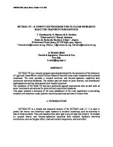
Fig. 10. Sample object (top) is composed in three different parts and materials. The large box of water (a) is 30 x 35 x 12 cm3, and the sphere (b) with the diameter of 5 cm is filled with air. The small 5 cm-cube, which is stuck in the side wall of the large box, is aluminum or lead. X-ray images were simulated with the energy of 100 keV and the cube of aluminum (bottom left) and lead (bottom right).
Two images of Al step wedge were simulated with 80 kVp X-ray spectrum and 7 x 7 area source in the counting mode (Fig. 9. left) and the current mode (right). There is not much 841
difference in images, but it shows slightly high contrast in counting mode. The top of Fig. 10 shows a sample object which is composed in three different parts and materials. The large box of water (a) is 30 x 35 x 12 cm3, and the sphere (b) with the diameter of 5 cm is filled with air. The small 5 cmcube, which is stuck in the side wall of the large box, is aluminum or lead. X-ray images were simulated with the energy of 100 keV and the cube of aluminum (bottom left) and lead (bottom right).
[4] [5]
IV. CONCLUSIONS AND FUTURE WORKS In this study, a computer code was developed to simulate an X-ray imaging system, which is coded in the iterative data language (IDL). This code is composed in X-ray source, object and detection parts. The physical principles are the Xray attenuation law and the detecting probability based on deterministic methods. No scattering was concerned in this step, but it is possible to combine the algorithm for scattering effects later. A computer-aided drawing (CAD)-formatted file is used as the object geometry to make it convenient to describe complex 3-D object components. The number of pixel and the size of detector are variable in the part of a detector. Transmission images can be simulated with various X-ray energies, including spectrum, and various system geometries. As seen in the above example images, simulated images are quite acceptable. The simulation code has its graphic user interface, which makes it easy to perform selection of simulation parameters, images reconstruction and post-image processing. The code can be a basic framework for the virtual X-ray imaging system even though it is not perfect in the current stage. It is also expected to train X-ray imaging system-operators using this simulation program. We are planning to combine several reconstruction algorithms in future. From the simulated projection images, it is also possible to reconstruct lamino- or tomographic images, following the step of image processing. Therefore, we can estimate the effects of operation conditions or geometric parameters on the reconstructed images. The present state of the simulation code is insufficient to evaluate the effects from photon noise and scattering. Quantum noise and scattering algorithm should be added in future for the sufficient simulation. It is also needed to compare with the results from other simulation methods, for example MCNP, which can give scattering effects and quantum noises. These problem should be solved out and definitely be our next step. V. REFERENCES [1] [2] [3]
P. Duvauchelle, N. Freud, V. Kafandjian, D. Babot, “A computer code to simulate X-ray imaging techniques,” Nucl. Instr. Meth., vol. B170, pp. 245-258, 2000. T. Jensen and J. N. Gray, “RTSIM: A Computer Model of Real-Time Radiography,” Review of Progress in Quantitative Nondestructive Evaluation, vol. 14, pp. 353-359, 1995. F. Inanc and J. N. Gray, “Scattering Simulations in Radiography,” Appl. Radiat. Isot. vol. 48, no. 10-13, pp. 1299-1305, 1997.
0-7803-8257-9/04/$20.00 © 2004 IEEE.
842
R. Halmshaw, “Scattered radiation in industrial radiotherapy,” Br J NDT, vol. 35(3), pp. 113-118, 1993. K. Carney, B. J. Gilmore, G. W. A. Fogarty and L. Desponds, Catalogue of Diagnostic X-ray Spectra and Other Data: Report No 78, Institute of Physics and Engineering in Medicine, 1997.