PHYSOR 2002, Seoul, Korea, October 7-10, 2002
RETRAC-PC : A COMPUTER PROGRAM FOR NUCLEAR RESEARCH REACTOR TRANSIENTS BEHAVIOUR T. Hamidouche, H. Mazrou & K. Ibrahim Commissariat à l’Energie Atomique Centre de Recherche Nucléaire d’Alger – Algeria 02 Boulevard Frantz fanon, BP 399 Alger-gare, Algeria
[email protected],
[email protected],
[email protected] A. Bousbia-Salah Facoltà di Ingegneria, Università di Pisa Pisa-Italy
[email protected] ABSTRACT RETRAC-PC is a computer program specially developed for the simulation of the behaviour of Light and Heavy Water cooled Nuclear Research Reactors cores under transients and accidents conditions. The code provides a coupled neutronic and thermal-hydraulic capability with continuous reactivity feedbacks. The models used are based on point kinetics, one dimensional hydrodynamics and one dimensional heat transfer equations. The validation of RETRAC-PC has been performed against experimental data as well with as some benchmark calculations for protected and unprotected transients. This paper presents a summary of the main assessment of the code capabilities in simulating transient core behaviour under positive reactivity insertions and loss of coolant flow. 1. INTRODUCTION RETRAC-PC is a revised and enhanced version of the RETRAC code [1]. It is used to predict the reactor core behaviour under transient or accident conditions, such as reactivity or loss-of-flow accidents. This code handles either plate type or pin rod type fuel element. Its is based on coupled kinetic and thermal-hydraulics equations with adjusted feedback reactivity contribution, such as Doppler effect, clad and coolant temperature, and void effect.
PHYSOR 2002, Seoul, Korea, October 7-10, 2002
In this code, the reactor core may be represented by one single fuel pin or plate element, with homogeneous one dimensional fluid flow. Point kinetics equations, with up to 15 groups of delayed neutrons, are then used to determine the time dependent core power. The heat transfer model is based upon one dimensional radial heat conduction solution and one dimensional axial fluid flow through the coolant channel, allowing several flow regimes; single and two-phase states. Heat transfer coefficient, Fanning friction factor, and void fraction correlations are used taking into account the geometry, the convection regimes (forced, mixed, and natural) and the sub-cooled boiling regimes. The total reactivity feedback contribution is adjusted at each time step calculation taking into account Doppler effect, clad expansion, and coolant temperature and void presence. whereas the control rod reactivity is evaluated according to the nature of rod movement when scram occurs.
2. PHYSICAL MODELS 2.1. Kinetics model: The reactor power behaviour under transient conditions is determined through a numerical solution of the conventional point kinetics equations, with up to a fifteen (15) delayed neutron groups and time step adapted feedback reactivity [2]. This set of kinetics equations is resolved by using the modified Runge-Kutta method [3]. In this model, isothermal or temperature dependent feedback coefficients, with adjusted weighting factors, for Doppler, clad and coolant temperature, and void are allowed. The void reactivity is calculated during the subcooled nucleate boiling regime. After reactor shutdown, decay heat generation is calculated by using the UNTERMAYER and WELLIS relation [4]. The control rod reactivity is evaluated according to the nature of its insertion in core as specified by the user. 2.2. Thermal hydraulics model In the RETRAC-PC code, a single core lattice is chosen to represent the behaviour of any region in the core. The lattice consists in the radial direction of fuel - cladding - gap (if any) - coolant. and axially it is assumed to be composed by an upper plenum, an active fuel length and a lower plenum. The effects of complicated flow boundaries in the core are represented by equivalent flow resistance. One dimensional vertical flow and a homogeneous equilibrium flow are considered; the general mass, momentum, and energy conservation equations are used [5]. These equations are a set of quasi-linear hyperbolic partial differential equations and hence the method of characteristics is
PHYSOR 2002, Seoul, Korea, October 7-10, 2002
used to rewrite them as a set of ordinary differential equations [5], [6]. The numerical solution, is obtained using initial and boundary conditions. In this case the user can use either the DPV or the DVP boundary conditions as follows: 1. The DPV boundary condition means that the density and the pressure are both specified at the inlet flow boundary and the velocity is specified at the outlet 2. The DVP boundary condition means that the density and the velocity are both specified at the inlet flow boundary and the pressure is specified at the outlet. The heat conduction and the energy conservation equations [7] are coupled by the heat flux at the interface between the clad and the coolant. The heat conduction equation inside the fuel element is written in one dimension. Only the radial conduction is considered. The solution is obtained by applying a first order implicit finite difference formula. This leads to a tri-diagonal matrix form and therefore the THOMAS algorithm [8] is used. The heat transfer coefficient is calculated based upon one of the following coolant flow conditions: 2.2.1. Single phase flow a) Forced flow: In case of a forced turbulent flow, the DITTUS BOELTER, COLBURN or the SEIDER-TATE correlations [9] are optionally allowed in the code for Re > 2300, according to the user's specification. For the Heavy water coolant, the following correlation is used [ REF ] : Nu b = 0.0255 Re0b.8 .Prb0.4
(1)
In case of a laminar flow, 200 < Re < 2300, only the SEIDER-TATE correlation [9] is allowed. b) Mixed convection This mode of convection begins when the buoyant forces action becomes significant in forced flow [9]. In this case, the Nusselt number is evaluated by the following relation:
( Nu )
b Mixed conv.
=
V ( Vmix − V) ( Nu) Natural conv .+ ( Nu) Forced conv. . Vmx Vmx
(2)
VMix: Velocity at which the mixed convection starts. c) Natural convection The natural convection is established generally after flow reversal or during passive decay heat removal mode. The McAdams correlation is then used [10]:
PHYSOR 2002, Seoul, Korea, October 7-10, 2002
( ) = 013 . ( Ra )
Nu b = 0.59 Ra D h Nu b
0.25 f
0. 33
Dh
f
10' < Ra D h < 109 109 < Ra D h < 1012
(3)
2.2.2. Two phase flow: The heat transfer coefficient in partial sub-cooled nucleate boiling is calculated using the two-phase transition scheme due to BERGLES-ROHSENOW [11] In case of fully developed sub-cooled or saturated nucleate boiling, the heat transfer coefficient is given calculated using by either JENS & LOTTES, THOM [12] or Mc ADAMS [13] correlations, according to the user specification.
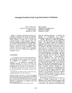
3. APPLICATION TO RESEARCH REACTORS 3.1. Experimental data: RETRAC-PC results have been assessed against two experimental data related to control rod insertion and withdrawal in a heavy water research reactor [14]. These experiments were conducted at low initial power levels and room temperatures to avoid steam formation which may induce post peak power oscillations. Also, long period tests have been chosen to avoid to reach in short time the safety reactor minimal period which activates the automatic reactor shut-down system. The experiments were initiated by moving upward (positive reactivity insertion) or downward (negative reactivity insertion) a peripheral control rod in order to alter fairly uniformly the core flux. Indeed the point kinetic equations are valid if the flux is representative of the flux integral over the core [6]. The overall results are given in reference [14]. Figures 1 and 2 show the RETRAC-PC results against the experimental data for the considered cases. The experimental data show that the reactor power increases exponentially during few seconds and then reaches a value of 750 kW. In comparison, the RETRAC-PC results show the same trends of the core response, and the calculated peak power reaches 810 kW. In fact, during the first 20 to 40 seconds of the trip, the power behaviour, no more influenced by the inherent feedback phenomena, is exponential; this behaviour is what is commonly known as the delay time response. A similar behaviour is also predicted by RETRAC-PC; the calculated results agree well with the experimental data, during these first seconds of the test. Later, the power runaway leaves significantly its exponential increase when the reactivity feedback effects related to changes in fuel and coolant temperature begin to act. The power reaches a peak and finally
PHYSOR 2002, Seoul, Korea, October 7-10, 2002
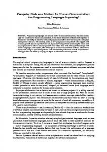
undergoes toward equilibrium at lower level. However, one can observe some discrepancies for equilibrium level of the power. This can be explained by the fact that in RETRAC-PC code, only the fraction of the coolant of the homogenized lattice is considered in the energy balance whereas in reality the feedback contribution is due to the whole moderator present in the core. The power decay response to the negative reactivity insertion test is displayed in Fig-2. Merely the same phenomena as in the first experimental test are observed in this case, except that the physical properties (either the core power or the coolant temperature) decreases instead of increasing. The degree of agreement between calculated and experimental data is typical of the results obtained for the first experiment.
1.00 EXPERIMENTAL DATA RETRAC-PC CALCULATED DATA
POWER(MW)
0.80
0.60
0.40
0.20
0.00 0.0
50.0
100.0
150.0
TIME (Sec)
200.0
Fig-1 Power Evolution during Control Rod Withdrawal Test
250.0
PHYSOR 2002, Seoul, Korea, October 7-10, 2002
0.50
EXPERIMENTAL DATA
POWER (MW)
0.40
RETRAC-PC CALCULATED DATA
0.30
0.20
0.10
0.00 0.0
20.0
40.0
60.0
80.0
100.0
120.0
TIME (Sec)
Fig-2 Power Evolution during Control Rod Insertion Test 3.2. Benchmark data Considered as a typical of large class of research reactors, the IAEA 10 MW BENCHMARK cores [15],[16] have been selected as standard for transient analysis of research reactors. These cores behaviour under some protected and unprotected accident conditions have been calculated by several scientific laboratories over the world and the results have been presented in reference [17]. So, in order to perform further assessment of RETRAC-PC code, these core transients have been performed and the results are presented here with comparison to those given in reference [17]. However, in the following are provided on Tables 1, 2 and 3 only the main results of RETRAC-PC and PARET [18] codes for both HEU and LEU cores [19]. As one can observe, there is a great concordance between the two codes results for all calculated parameters. However, in the following, a detailed comparison is presented only for LEU core in case of $1.5 /0.5 sec ramp reactivity insertion and of fast loss of flow.
PHYSOR 2002, Seoul, Korea, October 7-10, 2002
The reactor power transient histories given by the RETRAC-PC and the PARET codes, as shown on figure 1 3 are quasi identical and have the same trends. Figures 4, 5 and 6 show that fuel, clad and coolant temperatures, obtained by the two codes, have the same shapes up to the peak points. Right after, little differences take place. These differences are particularly more important for coolant temperature because, when using PARET code, extra amount of heat (about 4.5% of the total heat generated in the fuel region) is promptly deposited in the moderator region while this is not the case for RETRAC-PC calculations. This induces higher peak temperatures of fuel and clad and a lower coolant peak temperature. Some differences also appear around peak power. They are due to the differences of feedback models used by the two codes. In fact, the RETRAC-PC code uses a linear temperature dependant polynomial equation for feedback reactivity while PARET uses another model issued from SPERT experience [18]. $ 1.5 / 0.5 sec Ramp reactivity insertion HEU core LEU core RETRAC PARET RETRAC PARET Trip (sec) 0.608 0.609 0.572 0.573 Peak power, Mw 128.14 (0.655)* 129.01 (0.655) 127.70 (0.611) 126.57 (0.611) Energy at peak power, MJ 3.19 3.1 2.58 2.48 Maximal fuel Temperature, Deg. C 173.99 (0.667) 169.42 (0.671) 171.10 (0.624) 164.70 (0.624) Maximal fuel Temperature, Deg. C 158.59 (0.668) 155.25 (0.672) 151.34 (0.627) 149.20 (0.628) Maximal fuel Temperature, Deg. C 83.34 (0.746) 84.32 (0.760) 73.91 (0.710) 70.64 (0.737) * quantities between brackets are time (in seconds) of defined parameters occurrence. Parameter
Results of RETRAC-PC and PARET codes for reactivity transients 1E+3 ramp reactivity LEU
1E+2
Retrac-Pc
1E+1
Relative Power (%)
Table-1. :
Paret
1E+0 1E-1 1E-2 1E-3 1E-4 1E-5 1E-6 1E-7 0.0
0.1
0.2
0.3
0.4
0.5 0.6 0.7 0.8 0.9 1.0 TIME (Sec)
Figure 3 : Power transient
PHYSOR 2002, Seoul, Korea, October 7-10, 2002
180 ramp reactivity LEU
Fuel Temperature (Deg. C)
160
Retrac-Pc Paret
140 120 100 80 60 40 20
0.4
0.5
0.6 0.7 0.8 TIME (Seconds)
0.9
1.0
Figure 4 : Fuel Temperature transient 180 ramp reactivity LEU
160
Retrac-Pc
Clad Temperature (Deg. C)
Paret
140 120 100 80 60 40 20
0.4
0.5
0.6 0.7 0.8 TIME (Seconds)
0.9
Figure 5: Clad Temperature transient
1.0
PHYSOR 2002, Seoul, Korea, October 7-10, 2002
75 ramp reactivity LEU
coolant Temperature (Deg. C)
70
Retrac-Pc Paret
65 60 55 50 45 40 35 0.3
0.4
0.5
0.6
0.7
0.8
0.9
1.0
TIME (Seconds)
Figure 6 : Coolant Temperature transient
In case of fast and slow loss of coolant flow transients, the clad and coolant temperatures transients are shown by figures 7 and 8. One can observe the same trends for these temperatures throughout the transient time span prior to flow reverse. The discrepancies observed later are due to differences in the way each code is modelling this phenomenon. This modelling affects directly fuel, clad, and coolant maximal temperature variations as shown on table 2.
Slow loss of flow transient, V/Vo =exp(-t/T) with T=25 sec. HEU Core LEU core RETRAC PARET RETRAC PARET Power at Scram, Mw 11.62 (4.105) 11.60 (4.094) 11.67 (4.06) 11.59(3.87) 1st Fuel Temperature peak, Deg. C 86.36 (4.005) 86.43 (4.094) 87.75 (4.06) 87.20 (3.89) 1st Clad Temperature peak, Deg. C 84.54 (4.005) 84.55 (4.094) 84.89 (4.06) 87.20 (3.89) 1st cool. Temperature peak, Deg. C 58.86 (4.005) 58.95 (4.104) 59.01 (4.10) 58.63 (3.90) Fuel temperature at 15 % flow rate 49.88 45.28 56.03 45.31 Clad temperature at 15 % flow rate 49.80 45.23 55.13 45.23 Coolant temp. at 15 % flow rate 42.57 44.20 41.20 44.19 Parameter
Table-2 :
Results of RETRAC-PC and PARET codes for low loss of flow transients
PHYSOR 2002, Seoul, Korea, October 7-10, 2002
Fast loss of flow transient, V/Vo =exp(-t/T) with T=1 sec. HEU core LEU core RETRAC PARET RETRAC PARET Power at Scram, Mw 11.667 (0.362) 11.895 (0.362) 11.69 (0.172) 11.48 (0.199) 1st Fuel Temperature peak, Deg. C 89.81 (0.379) 89.86 (0.41) 90.93 (0.380) 90.96 (0.405) 1st Clad Temperature peak, Deg. C 88.06 (0.382) 88.07 (0.41) 88.17 (0.380) 88.06 (0.410) 1st cool. Temperature peak, Deg. C 60.05 (0.455) 60.18 (0.485) 60.10 (0.460) 60.18 (0.480) Fuel temperature at 15 % flow rate 54.80 52.57 54.87 56.80 Clad temperature at 15 % flow rate 54.66 52.39 54.63 56.45 Coolant Temp. at 15 % flow rate 46.05 48.79 46.62 47.20 Parameter
Table-3 :
Results of RETRAC-PC and PARET codes for fast loss of flow transients
90.0 Slow loss of flow Retrac-PC
Temperature (Deg. C)
80.0
Paret
70.0 60.0 50.0 40.0 30.0
0.0
Figure 7:
10.0
20.0 30.0 Time (Sec)
40.0
50.0
Results of RETRAC-PC and PARET codes for slow loss of flow (LEU)
PHYSOR 2002, Seoul, Korea, October 7-10, 2002
100.0
Fast loss of flow Retrac-PC
Temperature (Deg. C)
90.0
Paret 80.0 70.0 60.0 50.0 40.0 0.0
Figure 8:
0.5
1.0
1.5 2.0 TIME (Sec)
2.5
3.0
Results of RETRAC-PC and PARET codes for fast loss of flow transient (LEU) CONCLUSION
The main aim of this paper is to present assessments of the RETRAC-PC capabilities in predicting dynamic nuclear research reactor core behaviour during transient conditions. For these purpose two common transient categories were considered : The Fast transients, where kinetic effects predominate the system evolution, and the Slow transients where thermalhydraulics phenomena are predominant. A wide range of transients was investigated as well as two different enriched fuel core types. In general, the results obtained agree well with the experiments and with the results obtained by other codes such as PARET for the Benchmark transients. However, more assessment studies using experimental (protected and destructive) data of the SPERT-1 reactor are needed to demonstrate the reliability of the code. ACKNOWLEDGEMENT This work was performed under the auspices of Algerian Atomic Energy Commission (COMENA), in cooperation with the International Atomic Energy Agency (IAEA) through a Contract Research Project CRP-ALG-9758. The authors would like to express their special thanks to Dr. B. Baggoura for its fruitful comments and suggestions and to Mr Y. Touil for reviewing this paper. Moreover, we appreciate with thanks the financial support kindly granted by Dr. S. Hassani, Director General of the Nuclear Research Center of Algiers to take part to the present conference. REFERENCES
PHYSOR 2002, Seoul, Korea, October 7-10, 2002
[1] B. Baggoura, A. Bousbia Salah, and T. Hamidouche, ‘RETRAC: A Computer Code for the Analysis of Materials Test Reactors’, Nuclear Science and Engineering, Vol 118, 1994. [2] T. Hamidouche and A. Bousbia-salah: “ RETRAC-PC: A computer program for the analysis of transients in nuclear research reactor cores. Part I: Description of models” COMENA-CRS-R-418, 1998. [3] E. R. Cohen: “Some topics in reactor kinetics”, Proceeding of Second International Conference on Peaceful Uses of Atomic Energy, 11, 302-309, 1958. [4] J. R. Lamarsh, “Introduction to Nuclear Reactor Theory”, Addison-Wesley edition, 1983. [5] K. Kobayashi and K. Namatame, “Method of Characteristics for Solving Axi-Symmetric Two-Dimensional Flows”, JAERI-M 5969, January 1975. [6] Shoichiro Nakamura, “Computational Methods in Engineering and Science with Applications to Fluid Dynamics and Nuclear Systems”, Ohio State University, A Wiley-Inter-science Publications, 1977. [7] Harold Ethervington, “Nuclear Engineering Handbook”, Mc Graw Hill Book Company, 1968. [8] A. Gourdin, M. Boumahrat, « Méthodes Numeriques Appliquées’’, Office des Publications Universitaires, Alger, 1991. [9]
S. Kakaç, R. K. Shah, W. Aung, “Hand-Book of Single-Phase Heat Transfer”, A Wiley-Inter-science Publications, 1987.
[10] R. Giblin, ‘‘Transmission de la Chaleur par Convection Naturelle’’, Ed Eyrolles, 1974. [11] A. E. Bergles, J. G. Collier, J. M. Delhaye, G. F. Hewitt F. Mayinger, “Two Phase Flow and Heat Transfer in the Power and Process Industries”, McGraw-Hill Book company 1981. [12] John. G. Collier, “Convective Boiling and Condensation”, McGraw-Hill Book company, 1981. [13] R. P. Morgan, “A Review and Discussion of Literature Concerning Transient Heat Transfer and Steam Formation”, IDO-17226, 1967.
PHYSOR 2002, Seoul, Korea, October 7-10, 2002
[14] A Bousbia-salah & Rachid Berkani, “Analysis of reactivity insertion experiments in a nuclear research reactor core and comparison with RETRAC-PC computational resuts”, Algerain Review of Nuclear Sciences, Vol 3, Nos 1 &2 (2001) 79-84, 2001 [15] IAEA, “U.S Generic Enrichment Reduction Calculations for Plate-type and Rodded Type Research Reactors (RERTR Program)”, IAEA TECDOC-233, 1980. [16] IAEA, “research reactor core conversion guidebook”, IAEA TECDOC-643, 1992. [17] H. Mazrou, T. Hamidouche, K. Ibrahim and A. Bousbia-salah: “ development of a system of computer codes for the safety analysis of nuclear research reactor cores”, Progress report IAEA Research Contract Alg-9758, 1998. [18] C. Obenchain “PARET: A Program for the Analysis of Reactor Transients”, AEC Research and Development Report IDO-17282, Phillips Petroleum Company, 1969. [19] T. Hamidouche and A. Bousbia-salah: “Analyse comparative d’accidents par les codes RETRAC et PARET”, COMENA-CRS-R-421, rapport COMENA, 1996.