Available online at www.sciencedirect.com
ScienceDirect Procedia CIRP 10 (2013) 194 – 202
12th CIRP Conference on Computer Aided Tolerancing
A concurrent design method for functional tolerance and structure based on the principle of decomposition and reconstitution Heng Zhang, Yanlong Cao*, Yanding Wei, Jiangxin Yang Institute of Modern Manufacturing Engineering, Zhejiang University,38 Yugu Road, Hangzhou 310027, China
Abstract To assure feasibility and economy of mechanical product design, tolerance design should be incorporated into conceptual structure design phase. The completion of the evolving procedures from functional requirement to tolerance scheme resolution in the early stage, greatly promotes selection of structure scheme and optimization of cost. The paper provides a concurrent design methodology for functional tolerance using the principle of decomposition and reconstitution using growth design based on functional surfaces. A concurrent design methodology is given, including growth design-supported structure-tolerance design process, assembly information model and TTRS-based tolerance representation model. A recursive design method for function to structure mapping is proposed, and the tolerance design in every step of the iteration is focused on. Geometric variation model is introduced to infer key parts and key features, helping forming tolerance specification while assuring rationality and sufficiency of structure decomposition. In the whole process, structure and tolerance are constrained to each other and an optimization framework is put forward. Open access under CC BY-NC-ND license. © © 2013 2012 The The Authors. Authors. Published Publishedby byElsevier ElsevierB.V. B.V. Selection and/or peer-review under responsibility of Professor Xiangqian Jiang. Selection and peer-review under responsibility of Professor Xiangqian (Jane) Jiang
Keywords: growth design, concurrent design, functional requirement, tolerance design;
1. Introductiona Tolerance design is usually carried out on detailed geometric entities after structure design process [1]. If accuracy problems occur during tolerance design, designer has to return to the structure design to modify. Due to lack of consideration of tolerance in the early stage, design process can hardly be successful in one time which leads to inevitably increasing cost and time. In order to achieve efficient optimization between structure and tolerance, concurrent design is necessary. Nowadays, few works have comprehensively considered the tolerance design in the conceptual structure design stage. Narahari Y [2] has proposed a method called DFT (design for tolerance) with a function-assembly-behavior model. Based the model, he has given detailed design activities at successive stages * Corresponding author. Tel.: +0086-571-87953198; fax: +0086-571-87951145 . E-mail address:
[email protected].
in design, along with methods and best practices for tolerance analysis and synthesis. Roy U [3] has proposed a design synthesis process for evolution of a product, which forms a mapping from functional requirements to artifact in multiple stage of design evolution. Dantan JY [4] has put forward a methodology called ITP (Integrated Tolerancing Process) to ensure tolerance traceability. He has built relationships between tolerance and function (or decomposed sub-function). Mantripragad [5] has put forward a top-down tolerance design method that supports assembly model, based on which assembly order and assembly tolerance are studied. Most of those literatures have clearly pointed out the existing problems and demonstrated the importance of the tolerance design in the early stage. Some problem-solving related theories have been developed, yet, specific practical resolution scheme is still needed to be exploited. This paper has developed a concurrent design theory and approach for functional tolerance and structure
2212-8271 © 2013 The Authors. Published by Elsevier B.V. Open access under CC BY-NC-ND license. Selection and peer-review under responsibility of Professor Xiangqian (Jane) Jiang doi:10.1016/j.procir.2013.08.031
Heng Zhang et al. / Procedia CIRP 10 (2013) 194 – 202
195
based on the principle of decomposition and reconstitution on the basis of the growth design of products. Starting from primitive requirement of the product, prototype constructed by functional surface is created. Firstly, the general concurrent design method is proposed, including three major aspects, i.e. growth design-supported structure-tolerance process, assembly information model and tolerance representation model. A recursive design approach between functional and structure field is later developed to grow new structure while meeting the functional requirement of each level of the product. Then the tolerance design in each step of iteration is focused on. TTRS-based geometrical variation model of tolerance zone and datum reference frame are introduced to play an important role in deducing key parts and key features while assuring the sufficiency and rationality of the decomposition of the structure. With tolerance type automatically defined, the specification chain could be established for tolerance synthesis in the later procedure. With decomposition of the product function requirement, function can be realized in certain particular geometrical structure, and tolerances help to validate whether the function requirement is met. Also, function and conceptual structure optimization is discussed. In the second section, some ground work about theoretical basis of concurrent design will be presented; a concurrent tolerance-structure design process is detailed in the third section; in the fourth section, tolerance design in the concurrent design procedure is focused on, including assembly information model and a specification method based on a representative model. Also, optimization between tolerance and structure is given.
function-to-structure mapping is usually difficult to build due to its nonlinear factor. To precisely describe the function of product and to give attention to the structure information, we need to find a carrier which should have: 1) simplicity; 2) standardization 3) information independency [7]. Considering factors above, we introduce concept of function surface to the functionstructure mapping. Functional surface assumes certain functionality in a product, such as positioning, clamping, supporting, sealing, etc.; meanwhile, it has certain geometrical attribute, such as form, orientation, position, etc. As an information carrier, it plays an influential role in transmitting information between function and structure. Therefore, a mapping of function-functional surfacestructure could be established (see Fig. 1).
2. Theoretical basis
Theoretically speaking, all things are able to be decomposed. The decomposition process requires analytical study of the particular domain and design purpose. Fig. 2 gives two examples respectively about decompositions of structure and function requirement. An assembly could be decomposed into sub-assemblies, parts, features, surfaces, lines and points in the order of granularity. A FR (functional requirement) could be decomposed into several sub-FRs layer by layer. Decomposition is usually carried out in accordance to the different design stage, a commonly used procedure being in the order of: 1) functional (action principle); 2) qualitative (structure design); 3) quantitative (parameter computation and optimization). Reconstitution is to synthesize. When applying reconstitution to the structure design of mechanical product, the granularity should be particularly taken into account according to the specific design requirement. Table 1 [8] gives a comparison of reconstitution difficulty, structure reconstitution space and creativity
Concurrent tolerance and structure design requires a design platform that supports conceptual structure design. Growth design is such a platform for creative design [6]. The design process of growth design is analogous to creatures’ growth. From the primitive prototype of the product, implementation parts, transmission parts, structural parts and original moving parts are consecutively growing to form the final structure. In the growth design process, we will focus on the concept of functional surface to transmit information of function, structure and tolerance, which lays the foundation of the concurrent design and optimization. 2.1. Functional surface The essential of the design of product is to resolve the mapping from function to structure. However, due to the diversity and complexity of the structure of product, the
Fig.1. mapping of function-functional surface-structure
Function surface is the minimum unit composing a complex mechanism, able to effectively and flexibly express product information in the bottom level. It can be extracted from functional requirement to accommodate concurrent process in assembling and manufacturing, which is suitable for creative and automatic design. We will use function surface as a basic unit in the growth design. 2.2. Principle of decomposition and reconstitution
196
Heng Zhang et al. / Procedia CIRP 10 (2013) 194 – 202
during different level of granularity of structure decomposition. From the comparison, it’s easy to understand that why we choose feature and surface as the studied units. They are relatively suitable for dynamic growth design with a various and flexible combination resolution, yet not too difficult to reconstitute like lines and points. Though problems will be encountered during the reconstitution of features and surfaces, corresponding technological approach like functional mode and entity reconstitution technology can be applied to cope with. Table 1. Granularity of decomposition and reconstitution Creativity
Granularity of decomposition
Difficulty of Reconstitution
Mechanism
very easy
Structure reconstitution space almost none
Part
easy
small
poor
Feature
average
average
average
Surface
difficult
big
good
Line, Point
very difficult
very big
very good
very poor
2.3. Growth design Growth design is a top-down design, being modeled on the assembly level first. Starting from the primitive function of the product, initial prototype that fully represents functional requirement is created with functional surfaces, and begins layer-by-layer growth process like creatures [9]. During the process, functional surfaces are the basic units; different functional modes (i.e. implementation mode, transmission mode, structural mode and original moving mode) are the drive; decomposition and reconstitution are the basic principle of growth process; functional information, structure information, kinematic information and assembly information that attached to the function surfaces can be treated as constraints to control the growth. Under designer’s macro-control, implementation parts,
Fig.2. decomposition of structure and function requirement
transmission parts, structural parts and original moving parts are consecutively growing form primitive prototype to the final structure. Growth design based on functional surface provides a solid platform to perform concurrent tolerance-structure design. 3. Concurrent tolerance-structure design process 3.1. Structure and tolerance Concurrent tolerance-structure design is a top-down process along with conceptual parts growing. Customer’s requirement are first transformed into initial requirement on the functional surface; functional modes are chosen to perform the growth design next; then the fit and contact between functional surfaces are analyzed to assure complete constraint of structure and to find latent tolerance problem; finally tolerance are specified, analyzed and evaluated. All procedures constitute a progressive design process from qualitative to quantitative, form general to specific and from nominal structure to variational entity. In every stage of the process, there are evaluation methods to feedback to the former stage. Designer’s attempt can be easily expressed in the structure design, by clearly knowing through which surfaces and feature the accuracy are transmitting. In the concurrent process, structure and tolerance are evolving simultaneously [4]. Fig.3 is a tolerancing process graph showing overall procedures to deduce geometrical tolerance from initial requirement and relation. Requirement is transformed into function of product and the behavior of the product shows how to achieve certain function. Product’s behavior is realized by some geometrical structure. Tolerance is derived from analyzing geometrical requirement decomposed from the general requirement. During the whole process, the structure leads to define tolerance and tolerance in turn constrains structure.
Heng Zhang et al. / Procedia CIRP 10 (2013) 194 – 202
Fig.3. tolerancing process graph
The major task in the concurrent tolerance-structure design process is the decomposition of the tolerance. In the conceptual design process, tolerance specified on the functional surface during the former stage is intended to be decomposed along with the surface decomposition. In that case, one tolerance specification may split into several specifications, which should still meet the requirement when reconstituted. 3.2. Concurrent tolerance-structure design In the concurrent tolerance-structure design process, we should clearly determine how structure and tolerance can be evolving simultaneously. We here adopt a recursive design method by mapping the functional requirement to detailed structure. The structure newly created would create new functional requirements, which needs to be realized by more decomposed structure. In such a way, the recursive procedures including many
Fig. 4. A recursive method for function-to-structure mapping
steps (depending on the number of the decomposed layers) could be carried out. Also, tolerance design method during every step of the recursive process is studied, illustrating developing tolerance information on functional surfaces. On the newly created structure, it is important to determine the key features and key surfaces. The procedure not only helps form a specification chain, based on which tolerance allocation and optimization is developed, but also in turn indicates the sufficiency and rationality of the decomposition of structure. The two methods mentioned above should be combined in the application of concurrent design. They will be elaborated as following. Generally speaking, growth design-based concurrent tolerance design is process of decomposition and reconstitution. The recursive process can assure the efficient choosing of proper structure to realize the functional requirement. Once the function is not completely met, quick feedback is available to return to the upper layer of the design process, avoiding excessive time-consuming and increasing of cost. When mapping from general function to detailed structure, the top-level functional requirement is consecutively decomposed, until achieving a set of specific geometrical entities to realize. Both function and structure are decomposed into several layers in a complete design process, and designer carries out the work between function field and structure field. In Fig. 4, a recursive method for function-to-structure mapping is illustrated. Designer should analyze the general functional requirement (FR) first and then search for proper structure and develop an assembly model with functional surfaces. Designer should return to the FR field as the newly founded structure would create new functional requirements (FR1, FR2), which needs to be realized by more decomposed structures. FR1 and FR2 are decomposed from FR, together they should still represent the full requirement. Designer then analyzes
197
198
Heng Zhang et al. / Procedia CIRP 10 (2013) 194 – 202
FR1 and FR2, and based on the upper-layer structure, he should choose functional modes to grow new structures (sub-assemlby1, sub-assembly2). Sub-assembly1 and Sub-assembly2 are decomposed from assembly and they should assume the function requirement respectively of FR1 and FR2. During every step of design process, designer would go from the function filed to structure field and then return to the function field. Using the recursive design between function field and structure field, FRs are realized layer by layer until the requirement does not need to be decomposed again. In every step of the recursive design for function-tostructure mapping, tolerance design is requested. It contains two parts: assembly analysis and detailed tolerance design, as shown in Fig. 5. Assembly analysis is to make clear of composition of newly formed structure and new requirement. Detailed tolerance design is to determine detail tolerance information onto the key features and surfaces.
assembly analysis
requirement analysis
4. Method for Tolerance design in concurrent tolerance-structure design process
new assembly graph
4.1. Assembly model
identification of key features and key surfaces
detailed tolerance design
(ii) New assembly graph: The new assembly graph should be established with information of new parts and features and their relations. Along with the existing parts and features, the graph is the foundation for later tolerance design. In the detailed tolerance design: (i) Identification of key features and key surfaces: With the requirement analyzed before, variation models are built to validate datum reference frame, and key features and key parts can be inferred. (ii) New specification chains: With key parts identified and DRFs validated, tolerance types are generated and new specification chains are founded. (iii) Tolerance allocation: tolerance value should be determined after the detailed specification. (iv) Tolerance evaluation and optimization: optimization of structure and tolerance is carried out by founding feedback from tolerance to structure. The detailed tolerance design procedure and key technologies are presented in the next section.
new specification chains
tolerance allocation
tolerance evaluation and optimization
Fig. 5. tolerance design
In the assembly analysis: (i) Requirement analysis: During every step of the function-to-structure mapping, the structure will be more detailed. Along with the change of the nominal structure, the functional requirements will also be decomposed, in which case, design should scrutinize the newly created structure and analyzed the sub-requirements. Those subrequirements are of great importance, because they will be reflected in the new assembly graph and also will be defined as head of the specification chains in the later tolerance design.
During every step of the function-to-structure mapping, an assembly model should be first built as the foundation of later works. The minimum entity involved in assembly process is surface. Using functional surfaces where actual assembling connection happens, is a direct and effective way to describe the assembly relation between parts. We use graph theory to build assembly model that supports concurrent tolerance design. Based on assembly oriented graph (AOG) [10], some improvements have been made to express the assembly information. As shown in Fig.6, Every big circle (referred as node) represents a part, while the small circles inside the big circle represent functional surfaces of the part; Arrows on oriented arcs point to the positioned part (pointing from the lower part to the upper part), each oriented arc representing an assembly positioning joint; Property information is on every oriented arc (representing the property of assembly positioning joints), including the preponderance order of assembly positioning joints (primary, secondary or tertiary), invariance class of two assembling functional surfaces forming assembly positioning joint, and also information of contact/fitting.
Heng Zhang et al. / Procedia CIRP 10 (2013) 194 – 202
Fig. 6. improved AOG.
This graph theory-based assembly model has contained all kinds of constraining relations between functional surfaces. Parts or sub-assembly in the model can be decomposed into more detailed structure in concurrent design process, while the improved AOG expanding accordingly. The model can clearly express the special structure of a complex product and surface relations during every step of the recursive design, as shown in Fig.7.
Fig. 7. Assembly model during each single step of a recursive design
4.2. Tolerance specification using TTRS-based representation model During every step of design for function-to-structure mapping, new structure and new functional requirement will be created. Three-dimensional tolerance chain should be specified on the new structure on the basis of improved AOG. New functional requirements should be analyzed and key parts and key features are determined by a set of topological rules. DRF (Datum reference frame) is validated and tolerance type is deduced. In the structure design, we have chosen functional surface as the minimum growth unit. To keep consistency of the basic principle involved in the whole process and to assure the integration of tolerance design and structure design, we introduce TTRS-based tolerance representation model in the tolerance design stage. TTRS (technologically and topologically related surface),
199
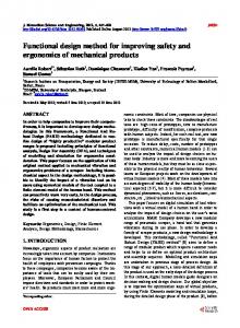
proposed by Clement et al., has classified surface into 7 types according to its invariance degree [11][12][13].We choose FRx in the function field to analyze and form initial specification on the ending part. Based on the TTRS-based tolerance representation model, geometric variation model of both tolerance zone and DRF are built for the purpose of further analysis. Tolerance zone is characterized first, using geometric variation model. Geometrical variation of surface (or its derived feature) is limited by tolerance defined. So we can establish model of tolerance zone by invariance degree. As shown in Fig. 8, the perpendicularity is specified on the left surface with the bottom plane being datum. The tolerance zone is the area between two parallel planes perpendicular to the bottom plane. Translation along axis x or z and rotation around axis y do not change the tolerance zone and its geometric constrains, due to the property of the specified surface (planar); furthermore, perpendicularity does not limit the translation along axis y and the rotation around axis z, which brings two additional invariance degrees, due to the property of orientation tolerance. Therefore the total invariance degree of the tolerance zone is
TI [(Tx Tz Ry ) Ty Rz ]
(1)
It is easy to recognize the constrained direction of the specified feature by analyzing related tolerance zone. The invariance degrees that DRF limits must include the functional direction of the specified feature, which also represents the range of variation of the specified feature. Comparison between the geometric variation model of DRF and tolerance zone helps to validate a DRF. By treating a DRF as a new TTRS derived from reconstitution of several TTRSs, which belongs to one of the seven invariance classes, we can analyze its topological relation with the tolerance zone. A set of topological rules are made to help valid a DRF. For a valid DRF, it must conform to: Rule No.1: For a tolerance on the specified feature whose derived feature is a line (axis, edge), if the tolerance is specified only in one direction, the tolerance should be equally treated as tolerance on specified feature whose derived feature is a plane. Rule No.2: For an orientation tolerance zone on the specified feature whose derived feature is a line (axis, edge), the functional direction of the DRF is parallel to that of the tolerance zone. Rule No.3: For an orientation tolerance on the specified feature whose derived feature is a plane, the functional direction of the DRF is orthogonal to that of the tolerance zone.
200
Heng Zhang et al. / Procedia CIRP 10 (2013) 194 – 202
Tolerance zone
t
u
A z
A
x
y
u
w
Fig. 8 model of tolerance zone
Rule No.4: For a position tolerance on the specified feature whose derived feature is a line (axis, edge) and DRF is of Cc or Cr, its functional direction is parallel to that of the tolerance zone and MGRE of DRF and tolerance zone coincides. Rule No.5: For a position tolerance on the specified feature whose derived feature is a line (axis, edge) and DRF is of Ct , its functional direction is orthogonal to that of the tolerance zone. Rule No.6: For a position tolerance on the specified feature whose derived feature is a plane and DRF is of Cp or Cr, its functional direction is parallel to that of the tolerance zone and MGRE of DRF and tolerance zone coincides. Rule No.7: For a position tolerance on the specified feature whose derived feature is a plane and DRF is of Ct, its functional direction is orthogonal to that of the tolerance zone. Rule No.8: If DRF is of Cx , it is always valid. Here, Cp stands for planar invariance class, Cc stands for cylindrical invariance class, Cr stands for revolutional invariance class, Ct stands for prismatic invariance class, and Cx stands for compound invariance class. When a DRF is being validated, Rule No.1 should be always checked first, to determine the specific validating case. Then a search should begin from Rule No.2 to Rule No.7. If the DRF conforms to one of these 6 rules, then the search ends and the DRF is valid; if not, Rule No.8 is examined. If after examining Rule No.8, the DRF conforms to none of these 8 rules, the DRF should be reselected. We have given an example to illustrate the process. In Fig. 9 is a simple part with two features to be specified (S1, S2). Three datums A, B, C are selected to form the DRF. First, invariance degrees of position tolerance zone are depicted. Then we validate DRFs in order of A, A-B, A-B-C. Clearly DRF A is not sufficient for S1 and S2, so DRF A-B belonging to a prismatic TTRS, is taken into consideration. For S1, DRF A-B is valid as it conforms to
Rule No. 3. So DRF A-B-C is no longer necessary to be examined and the specification result is presented as in Fig. 9. For S2, however, DRF A-B could not conform to any eight rules above, so datum C should be added to form DRF A-B-C, a TTRS of compound invariance class.
Fig. 9. geometric variation model of tolerance zone and DRFs
With the procedure of DRF validation, key parts and key features are automatically and indirectly determined. Requirements can be decomposed from upper parts to lower parts. Tolerance specification chain is able to be constructed on functional surfaces on key features. Form tolerance symbol is chosen according to the form of specified functional surface; orientation and position tolerance symbol is chosen according to the orientation and position of the specified functional surface relative to DRFs (see Fig. 10). Tolerance type changes according to the property of surface or its relation to the datum. Whether the symbol is needed is judged by the form of the tolerance zone. form orietation position Fig. 10. choice of tolerance type
Heng Zhang et al. / Procedia CIRP 10 (2013) 194 – 202
4.3. Tolerance allocation and optimization for concurrent design When specification chain has been constructed, the variation of entities should be quantified by tolerance allocation. Many approaches are developed to help tolerance allocation. A traditional way is to use tolerance-cost function as the objective function, and to set boundary conditions and assemblability as constraints. This paper does not elaborate the detailed method, please refer to [14]. After the function-to-structure mapping and tolerance design, it is necessary to optimize tolerance and conceptual structure based on their mutual relation. Many ways of feedback can be built to modify the structure and tolerance thanks to the concurrent environment. Based on the result of tolerance allocation during every step of recursive design, the newly created nominal dimension of part can be modified; specification chains can be modified by choosing alternative DRFs; allocation method can also be modified. In addition, we can use tolerance to instruct structure design. In every step, if the tolerance is strict, typical positioning structure (instead of those that is difficult to obtain through manufacture) should be chosen when applying growth design with function modes, in order to maximize the tolerance value. Begin
Creation of new structure and FRs
Instructed structure design
Determination of nominal dimension
Modification of nominal dimension
Determination of key features
Construction of specification chain
Alternative choice of DRF
Tolerance allocation
Tolerance evaluation
Modification specification chain No
Yes End Fig. 11. optimization frame for concurrent tolerance-structure design
Detailed optimization frame for concurrent tolerancestructure design is shown as Fig. 11. Important procedures in concurrent design process that affects final tolerance chains are elaborated in chronological order. Tolerance evaluation is a critical procedure that determines whether the tolerance is acceptable. If not, several feedbacks on different level are provided to modify key factor in the concurrent tolerance-structure design. Since the feedback occurs in a single step of design, the feedback is timely with the structure decomposition and tolerance design, and modification will be efficiently applied. 5. Conclusion This paper has proposed an approach for concurrent tolerance-structure design. A concurrent design process is put forward on the basis of growth design theory and principle of decomposition and reconstitution. Assembly model using improved AOG and TTRS-based tolerance representation model provide foundation for tolerance design. Key technologies in concurrent design are demonstrated. A recursive design approach between functional and structure field is developed and the tolerance design in every each step of iteration is focused on. Geometric variation model of DRF and tolerance zone helps to validate DRF and infer key features and specification chains. Also an optimization frame for concurrent design is studied. The design process puts tolerance design in an early stage, along with the growth of structure. The methodology is feasible in implantation and effective in avoiding re-design. Acknowledgements We would like to acknowledge the support of the National Natural Science Foundation of the e P. R. China (no. 50975257 and no. 50835008) and the National Basic Research Program of P. R. China (973 Program, No.2011CB706505). References [1] Fang HF, Wu ZT. A research of concurrent design in computeraided design tolerance and process tolerance. China Mechanical Engineering 1995;06:25-7. [2] Narahari Y, Sudarsan R, Lyons KW, Duffey MR, Sriram RD. Design for tolerance of electro-mechanical assemblies: an integrated approach. IEEE Transactions on Robotics and Automation 1999;15:1062-79. [3] Roy U, Pramanik N, Sudarsan R, Sriram RD, Lyons KW. Functionto-form mapping: model, representation and applications in design synthesis. Computer-Aided Design 2001;33:699-719.
201
202
Heng Zhang et al. / Procedia CIRP 10 (2013) 194 – 202
[4]Dantan JY, Anwer N, Mathieu L. Integrated toleranclng process for conceptual deslgn. CIRP Annals Manufacturing Technology 2003;52:135-8. [5] Mantripragada R, Whitney DE. The datum flow chain: a systematic approach to assembly design and modeling research in engineering design. Research in Engineering Design 1998;10:150-165. [6] Zhang Y, Huang KZ, Gao CQ, Yang ZH. Tolerance study based on growth design. Chinese Journal of Mechanical Engineering 2006;42:143-7. [7] Dantan JY, Ballu A, Mathieu L. Geometrical product specifications - model for product life cycle. Computer Aided Design 2008;40: 493–501. [8] Huang KZ, Ai X, Zhang CR. Decomposition and reconstitution principle for complex surfaces and its applications. Science in China(Series E) 1997;40:89-96. [9] Yang B, Huang KZ, Stratified modeling in product growth design. Modular Machine Tool & Automatic Manufacturing Technique 2008;03:1-9.
[10] Ballu A,Mathieu L. Choice of functional specifications using graphs within the framework of education. Proc. of the 6th CIRP International Seminar on Computer Aided Tolerancing 1999;197206. [11] Clement A, Riviere A. Tolerancing versus nominal modeling in next generation CAD/CAM system. Proc. of 3th CIRP Seminars on Computer Aided Tolerancing 1993:97-114. [12] Clement A, Riviere A, Serre P, Valade C. The TTRSs: 13 constraints for dimensioning and tolerancing. Proc. of 5th CIRP Seminars on Computer Aided Tolerancing. 1997:122-131. [13] Clement A, Riviere A, Serre P. Global consistency of dimensioning and tolerancing. Proc. of 6th CIRP Seminars on Computer Aided Tolerancing. 1999:1-26. [14] Chase KW, Greenwood WH, Loosti BG, Hauglund LF. Least cost tolerance allocation for mechanical assemblies with automated process selection. Manufacturing Review.1990;3:49-59.