Email: {aarrieta, gsagardui, letxeberria}@mondragon.edu. AbstractâThe strong ... variability of the test system and its components together with the traceability ...
VALID 2014 : The Sixth International Conference on Advances in System Testing and Validation Lifecycle
A Configurable Test Architecture for the Automatic Validation of Variability-Intensive Cyber-Physical Systems
Aitor Arrieta, Goiuria Sagardui, Leire Etxeberria Computer and Electronics Department Mondragon Goi Eskola Politeknikoa Email: {aarrieta, gsagardui, letxeberria}@mondragon.edu Abstract—The strong demand for customizable products is leading to increase variability in cyber-physical systems. The need of dealing with variability issues increases complexity not only in the product, but also in the verification and validation activities. Due to the high amount of configurations that the system can be set to, verification and validation activities might become time consuming and non-systematic. In order to deal with these problems, this paper presents an automatically configurable test architecture together with a model-based process for the systematic validation of highly configurable cyber-physical systems, with the main objective of reducing verification and validation costs. The main contributions of this paper are the analysis of the variability of the test system and its components together with the traceability among the features of the cyber-physical system and the test system and a definition of a model-based process to achieve the test objectives. Keywords–Model Based Testing; Test Architecture; Variability; Configurable Systems.
I.
I NTRODUCTION
Modern society is depending on Cyber-Physical Systems (CPSs) in charge of controlling many individual systems and complicated coordination of those systems [1]. CPSs combine digital cyber technologies with physical processes, where realtime embedded and networked systems monitor and control physical processes with sensors and actuators [2]. Industrial CPSs are highly complex systems [1], and variability increases in order to deal with the changes that the physical environment requires. Variability is defined as the ability to change or customize a system [3], which can be understood as configurability (variability in the product space) or modifiability (variation or evolution over the time) [4]. Variability in CPSs can appear as configurability when different components or functionalities can be chosen or are optional depending on the customer’s needs or budget, e.g., different temperature sensors with different precision. In addition, modifiability appears when a new feature or functionality is added to the CPS, e.g., apart from measuring temperature, humidity is wanted to be measured. Run-time variability is also common in CPSs, which permits the adaptation to changes in the environment. Testing configurable CPSs can become a very time and resource consuming activity. This is, to a large extent, caused by the high number of possible variants, which give to the system the chance of being set into thousands of configurations, making the testing of all the existing combinations really
Copyright (c) IARIA, 2014.
ISBN: 978-1-61208-370-4
infeasible. The high number of variants and their complexity make manual configuration of variability-intensive CPSs error-prone and inefficient, which warrants the need for an automated solution for CPS configuration [1], as well as for its test system. Traditional software testing activities can reach even the 50 % of the development costs [5], which can be incremented if the System Under Test (SUT) is highly configurable. ModelBased Design (MBD) tools help in the development of embedded software, a task which is becoming more and more complex, especially when variability issues have to be taken into account. Model-, Software-, Processor- and Hardware-inthe-Loop (MiL, SiL, PiL and HiL) tests, provide four testing phases [6], which are typically used to test CPSs in different stages and testing objectives. According to Berger et al. [7], the automotive domain is the industry where variability modelling is most used, and MATLAB/Simulink is a modelling language widely used for modelling embedded software in this domain [8], as well as for simulating CPSs. This has been the main reason that has motivated us to choose MATLAB/Simulink as simulation framework to achieve our objective. Test architectures are the organization of the group of components in charge of testing a system. A test architecture is a necessary artefact for a testing process [9], so that verification and validation activities can be systematic, allowing among other advantages reusability of test cases along the different test phases. According to Nishi [10], test architectures can be differentiated into test system architecture and test suite architecture. The test system architecture focuses on issues such as test system, SUT, platform where the SUT is executed or test case generation, whereas the test suite architecture relies on groups of test cases, test levels, etc. [10]. The viewpoint of this paper will focus on the test system architecture. Two main challenges have been identified to efficiently test highly configurable CPSs. On the one hand, the definition of a test architecture that automatically gets configured for the selected configuration of the CPS. Each configuration of the CPS is different, with different ports, parameters, functionalities and requirements; therefore, the test architecture must be adapted to the selected configuration. On the other hand, the selection of the test cases that each configuration must execute. Each configuration requires a set of test cases to be executed depending on the selected components and the product requirements. In addition, it might be possible
79
VALID 2014 : The Sixth International Conference on Advances in System Testing and Validation Lifecycle
that some test cases had already been executed in a similar configuration and that can be avoided to save time.
model covering 100% pairwise interaction, and test cases are generated for each configuration.
This paper focuses on the first issue, how to automatise the configuration of a test architecture for configurable CPSs, which serves as a basis to develop a configurable test architecture in Simulink. Moreover, this test architecture is able of getting configured automatically taking into account the selected configuration for the configurable CPS. In addition, we propose a systematic process that enables reducing the validation time of configurable cyber-physical systems considerably.
Nevertheless, this combinatorial technique selects product configurations statically. In [15], a novel approach is presented named SPLat, where product configurations are determined dynamically during test execution by monitoring accesses to configuration variables. The technique consists on executing the test for one configuration, while observing the values of configuration variables used to prune other configurations.
The rest of this paper is structured as follows. Section II introduces the related work. Section III presents the configurable test architecture and the components composing it. In Section IV, the necessary steps to systematically test variability-intensive CPSs are introduced. Preliminary as well as expected results are described in Section V. Finally, Section VI provides the conclusions of this paper. II.
R ELATED W ORK
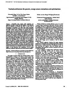
Model-in-the-Loop for Embedded System Test (MiLEST) is a toolbox for MATLAB/Simulink developed by ZanderNowicka [11]. The test architecture, depicted in Figure 1, is based on MiLEST, specially the test oracle and the test data generator. The hierarchy of MiLEST is divided into four abstraction levels: Test Harness level, Test Requirement level, Test Case level and Feature level. The main difference between the test architecture proposed in [11] and our test architecture is that the test architecture presented in this paper supports variability issues and we add an additional block named “Test Historic Database” with the main objective of reducing testing time. From the testing perspective, our previous work [9] presents an approach based on model-based testing and variability management integrated in Simulink, where a concrete configuration of the software is chosen by the test engineer, and the testing infrastructure is instantiated for the chosen configuration; the main shortcomings of this approach are that the plant model is not simulated and that important components such as test oracles do not handle variability. In another previous work [12], a testing architecture with variability management in the test oracles is proposed to test distributed robotic systems in Simulink; in this case, the main limitations of this approach is that it was only oriented for same purpose distributed systems, and the variability points were only modelled in a test oracle.
Another approach to reduce validation costs of highly configurable systems is minimizing the test suite for testing a product, reducing redundant test cases. A set of test cases can be automatically obtained by selecting features of a feature model to test a new product, but there still can exist redundant test cases [16]. A fitness function based on three key factors (Test Minimization, Feature Pairwise Coverage and Fault Detection Capability) for three different weightbased genetic algorithms is defined by Wang et al. [16]. This approach allows reducing the test suite covering all testing functionalities achieving a high fault detection capability. III.
T HE C ONFIGURABLE T EST A RCHITECTURE
A. Variability in the Test Architecture As depicted in Figure 1, our test architecture is composed by five sources: System Under Test (SUT), Test Data Generator, Test Oracle, Test Control and Test historic Database. The experiments performed by Weißleder and Lackner [17] show that the most efficient way to test configurable systems is including variability down to the test case level. The test architecture must deal with variability so as to be configurable. The following list describes the different components and defines where variability can be found: •
System Under Test (SUT): it is the CPS to be tested. The components can be divided into hardware and software, where the software can be configured as model or software. In this approach, the SUT is kept as black-box, what means that the test engineer does not need to be familiar with its internal behaviour [18]. Variability in a CPS can be found in the cyber as well as in the physical side. Variability in the physical side (commonly known as context variability) is related to the variability of the environment. In a previous work [19], we proposed a methodology to manage and model variability in plant models for CPSs.
A product line of validation environments with variability to test different applications in different domains and technologies is proposed by Magro et al. [13]. The main limitations of this approach are that the components handling variability are too high level components, it does not support test automation and variability is not managed with any tool.
•
Test Data Generator: it is the source in charge of stimulating the SUT with test signals. Variability in the test data generator can be found in signals (number and characteristic of each signal), requirements (number and parameters of requirements) and test cases (test case duration and test case characteristics).
Combinatorial testing is also widely used when testing configurable systems, where configurations are often selected using pairwise or t-wise techniques. Combinatorial testing techniques are commonly combined with model-based testing as proposed by Oster et al. [14], where a tool chain is introduced named MoSo-PoLiTe. This tool selects pairwise configuration selection component on the basis of a feature
•
Test Oracle: it is the source where the SUT behaviour is examined and the test result is determined by a verdict [11]. Variability in the Test Oracle might be found in signals (number of inputs to the oracle) and requirements (number of requirements, number of validation functions, validation function characteristics and requirement parameters).
Copyright (c) IARIA, 2014.
ISBN: 978-1-61208-370-4
80
VALID 2014 : The Sixth International Conference on Advances in System Testing and Validation Lifecycle
•
•
Test Control: it is the specification that executes test cases [11]. In the case of systems with many variants, it is important to reduce the testing time as much as possible because there are many configurations that must be tested. This source will execute test suite minimization algorithms to reduce the overall validation time, as well as test case prioritization algorithms to reduce the time needed to detect faults. Once the tests are finished, the test controller will send information of the results to the test historic database. Test Historic Database: the results of the generated test cases are stored in a database in order to firstly, have information of the quality of the system and secondly, to avoid testing the same features many times. The test historic database would store the tested configurations, verdicts of test cases, achieved coverage, versions of the tested SUT, etc.
Test Data Generator
SUT
Test Oracle
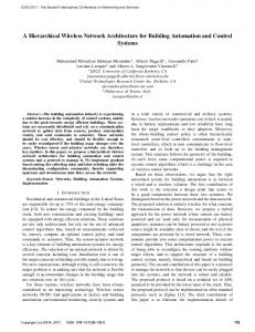
C. Traceability among Features, Feature Models and the Test Architecture Components We believe that using feature models to manage variability of the testing infrastructure, as shown in Figure 2, may help to automatically generate the components that comprise the test architecture. The selected feature modelling tool is FeatureIDE [26], which is an open source plug-in for Eclipse that can be modified to adapt it to our needs. FeatureIDE allows obtaining the .xml file of the developed feature model. Using a .xml parser in MATLAB it is possible to extract the data needed to automatically generate the test architecture. FeatureIDE also permits an automatic configuration (all possible configurations, t-wise configuration, etc.) or a manual configuration of products, which returns a file with an extension “.config”. This extension can be read from a model configurator developed in MATLAB that automatically configures the Simulink model (including the SUT and the test architecture) before running the test.
Test Control
Test Historic Database
Requires
Requires
Figure 1. Configurable Test Architecture (based on [11]).
Requires
Figure 2. Example of how the Test Feature Model looks like.
B. Managing and Modelling Variability The previous section has analysed where the variability can appear in a test architecture. However, this variability must be managed and modelled. Feature Modelling is the most used technique in industry to manage and represent variability of systems [7]. A feature model can be defined as a notation that represents features and relations among them of all possible product configurations [20]. Basic feature models represent features as “mandatory”, “optional”, “alternative” and “or”. Constraints among features also can appear in form of “Require” and “Exclude”. Figure 2 depicts an example of a feature model. MATLAB/Simulink can be used to model variability, as explained in several approaches in the literature. In [21], uniform variability is modelled using different mechanisms and blocks offered by MATLAB/Simulink, and variability is managed using the tool pure::variants [22]. In [8], different blocks are classified depending on their granularity, mapping of feature types, binding times and quality aspects. Another approach is presented Botterweck et al. [23], where variants are managed using a tool named S2T2 and variability is modelled in a similar way as explained in [21], but when the product is configured, the unselected features are erased from the model. Another interesting and different approach is presented in [24], named “Delta Simulink”, where “Delta Modelling” is used in Simulink models to model variability. In our previous work [25], we compared the main characteristics of the variability modelling and management approaches documented in the current state of the art.
Copyright (c) IARIA, 2014.
ISBN: 978-1-61208-370-4
We propose a motivating example involving the control of the liquid level of an industrial tank to better understand the proposed approach. The liquid can be water or a chemical product. When the liquid is a chemical product, it will be mandatory to measure its acidity with a pH sensor. Other variability points in the example are included: an optional temperature sensor, two different sensors to measure the liquid level and two types of gates to drain the liquid. The test feature model would have several branches, which can be divided into branches for the test system (Requirements, TDGen, TOracle) and the branches for the CPSUT, and both are related. To achieve this, constraints (“requires” or “excludes”) of the test feature model play an important role, as they define the relations among components of the product line and test cases. As shown in the example depicted in Figure 2, Temperature Sensor requires its corresponding test case, named “Test Case Temp”. When chemical liquid is selected, the pH Sensor is also selected, and two test cases needs to be executed: “Test Case Level Chemical” and “Test Case pH”. The same happens when the liquid is water. IV.
S YSTEMATIC M ODEL -BASED P ROCESS FOR THE VALIDATION OF H IGHLY C ONFIGURABLE C YBER -P HYSICAL S YSTEMS
We consider that it is essential to follow a systematic process to test variability-intensive CPSs. There are many possible configurations, which makes impracticable to test all of them and there is uncertainty of the achieved test coverage. Figure 3 depicts the overview of the model-based process that
81
VALID 2014 : The Sixth International Conference on Advances in System Testing and Validation Lifecycle
enables the systematic validation of highly-configurable CPSs. The components of the process shown in Figure 3 are classified into two phases following the theory of product lines: Domain Engineering and Application Engineering. The main difference between these two phases is that the components in the domain engineering are for the whole product line, and therefore variability is implemented. On the contrary, the components corresponding to the application engineering are for a concrete product configuration, where variability is already bound. In addition, seven steps are needed to carry out the whole process:
Domain Engineering Test Feature Model
1
.xml
Test Case Library
2
Test Architecture 3 Generator
.config
4
6
SW Model Library
Test Configurator
Simulation Framework
HW Model Library
5
Configurations Library
Application Engineering
•
Step 1: The test feature model has to be developed. This step is one of the most important ones as it will allow to manage and handle the variability of the test system, and later this will be used to automatically generate the test architecture.
•
Step 2: The .xml file of the developed test feature model is generated and saved to be manipulated by the test architecture generator. This .xml file is automatically generated by the tool FeatureIDE [26].
•
Step 3: The test architecture generator, which is implemented in MATLAB, parses the .xml file of the feature model and saves the needed information of the test architecture and its variability in MATLAB cell arrays. With the saved information, the test architecture will automatically generate the Simulink model of the test system integrated with the Simulink model of the CPSUT using MATLAB scripts.
•
Step 4: Configurations are generated either manually or automatically and stored in .config files in a library. These configurations are the ones that will later be tested. The tool FeatureIDE [26] allows either the manual or automatic generation of configurations. In the case of automatic configuration generation, combinatorial techniques, such as pairwise or t-wise, are used.
•
Step 5: The test configurator, which is implemented in MATLAB, parses the configuration files and the components of the simulation framework are configured. The different possible test cases (handling variability), and the models of the hardware and software components will be stored in their corresponding libraries. The test configurator will allocate the needed components in the correct place of the simulation framework and integrate them, removing the components that are not needed for the configuration with the objective of saving simulation time.
•
Step 6: When the simulation starts running, as mentioned before, the test controller will obtain information about previously executed test cases in order to prioritize and remove redundant test cases. Once processed the information about previously executed test cases, the simulation framework will test the selected configuration.
•
Step 7: The executed test results are saved in the database, and ready to test another configuration. For the second test run, it will be enough to start from the fifth step.
Copyright (c) IARIA, 2014.
ISBN: 978-1-61208-370-4
Test Historic Database
7
Figure 3. Overview of the Systematic Model-Based Process for the Validation of Highly Configurable Cyber-Physical Systems.
V.
R ESULTS
Preliminary results include the semi-automatic generation and configuration of the SUT. In this process, we extract data from a feature model and generate automatically the components of the SUT’s model in Simulink. The most challenging part is the automatic integration among the components, where the configurator needs information about the input and output ports of each component, i.e., their datatype, how are related with the other components, etc. The following step would be the automatic generation of the test architecture and its integration with the SUT. The proposed test architecture in combination with the presented model-based process allows testing systematically real-time CPSs that have to deal with many variants. In addition, the use of a test controller, which is communicated with the test historic database, and that contains algorithms for different test objectives, as well as to prioritize test cases and to remove redundant test cases will considerably reduce verification and validation time achieving high test quality. Another important issue for saving simulation time is the allocation of the components for the selected product, removing the features that are not specified in the configuration. We propose storing the different components in libraries and allocating them automatically in the Simulink model with the test configurator, as proposed by Arrieta et al. [19] for plant models. A test feature model has been proposed, but it has to be specified which is the data needed by the test architecture generator, as well as the optimal way of tracing components of the SUT with test cases. In addition, different modifications in the source code of the FeatureIDE tool might be needed to adapt the plug-in to our needs. VI.
C ONCLUSIONS AND F UTURE W ORK
This paper presented an automatically configurable test architecture that includes different sources to efficiently and systematically test variability-intensive CPSs. The test architecture is able of self-adapting to product configurations and
82
VALID 2014 : The Sixth International Conference on Advances in System Testing and Validation Lifecycle
automatically tests and obtains verdicts that represent results of the executed test cases. We have focused our approach for the validation of variability-intensive or highly configurable CPSs. As the SUT must deal with variability, the test architecture also has to handle variability. The first step taken has been the detection of the different variation points that the components of the proposed test architecture must deal with. Systems with many variants must use a tool to manage the variability. We have proposed to use Feature Models to manage variability as well as for the traceability among components of the SUT and test cases. A process with seven steps that enables testing variabilityintensive CPSs in a systematic manner has been proposed, starting from variability management with feature modelling and ending with an upload of test results in the test historic database. This paper has focused on the test architecture and its configurability. Although the test architecture plays an important role when testing highly configurable CPSs, it is also important to study the selection of the appropriate test cases. After developing the framework, it is expected to validate the whole process with different case-studies, desirably from the automotive domain. Additionally, we would like to compare and combine our variability modelling approach with other potential approaches, such as Delta Simulink [24] in test architectures. ACKNOWLEDGEMENTS
[9]
[10]
[11]
[12]
[13]
[14]
[15]
[16]
[17] [18]
[19]
This work has been developed by the embedded systems group supported by the Department of Education, Universities and Research of the Basque Government.
[20]
R EFERENCES
[21]
[1]
[2]
[3]
[4] [5]
[6] [7]
[8]
T. Yue, S. Ali, and K. Nie, “Towards a search-based interactive configuration of cyber physical system product lines,” in ACM/IEEE 16th International Conference on Model Driven Engineering Languages and Systems, Poster, 2013, pp. 71–75. P. Derler, E. A. Lee, and A. Sangiovanni-Vincentelli, “Modeling cyberphysical systems,” Proceedings of the IEEE (special issue on CPS), vol. 100, no. 1, January 2011, pp. 13 – 28. J. V. Gurp, J. Bosch, and M. Svahnberg, “On the notion of variability in software product lines,” in Proceedings of the Working IEEE/IFIP Conference on Software Architecture, ser. WICSA ’01. Washington, DC, USA: IEEE Computer Society, 2001, pp. 45–54. S. Thiel and A. Hein, “Systematic integration of variability into product line architecture design,” in SPLC, 2002, pp. 130–153. M. Blackburn, R. Busser, and A. Nauman, “Why model-based test automation is different and what you should know to get started,” in In International Conference on Practical Software Quality and Testing, 2004, pp. 87–90. H. Shokry and M. Hinchey, “Model-based verification of embedded software,” Computer, vol. 42, no. 4, 2009, pp. 53 – 59. T. Berger et al., “A survey of variability modeling in industrial practice,” in Variability Modelling of Software-intensive Systems (VaMoS), 2013, pp. 7:1–7:8. J. Weiland and P. Manhart, “A classification of modeling variability in simulink,” in Proceedings of the Eighth International Workshop on Variability Modelling of Software-Intensive Systems, ser. VaMoS ’14. New York, NY, USA: ACM, 2014, pp. 7:1–7:8.
Copyright (c) IARIA, 2014.
ISBN: 978-1-61208-370-4
[22] [23]
[24] [25]
[26]
G. Sagardui, L. Etxeberria, and J. A. Agirre, “Variability management in testing architectures for embedded control systems,” in VALID 2012 - 4th International Conference on Advances in System Testing and Validation Lifecycle, Lisbon, Portugal, 2012, pp. 73 – 78. Y. Nishi, “Viewpoint-based test architecture design,” in 2012 IEEE Sixth International Conference on Software Security and Reliability Companion, Gaithersburg, MD, USA, 2012, pp. 194 – 197. J. Zander-Nowicka, “Model-based testing of real-time embedded systems in the automotive domain,” Ph.D. dissertation, Technical University Berlin, 2008. A. Arrieta, I. Agirre, and A. Alberdi, “Testing architecture with variability management in embedded distributed systems,” in IV Jornadas de Computaci´on Empotrada, ser. JCE 2013, 2013, pp. 12–19. B. Magro, J. Garbajosa, and J. Perez, “A software product line definition for validation environments,” in 12th International Software Product Line Conference (SPLC), Piscataway, NJ, USA, 2008, pp. 45 – 54. S. Oster, I. Zorcic, F. Markert, and M. Lochau, “Moso-polite - tool support for pairwise and model-based software product line testing,” in VaMoS, 2011, pp. 79–82. C. H. P. Kim et al.,“Splat: Lightweight dynamic analysis for reducing combinatorics in testing configurable systems,” in Proceedings of the 2013 9th Joint Meeting on Foundations of Software Engineering, ser. ESEC/FSE 2013. New York, NY, USA: ACM, 2013, pp. 257–267. S. Wang, S. Ali, and A. Gotlieb, “Minimizing test suites in software product lines using weight-based genetic algorithms,” in Proceedings of the 2013 Genetic and Evolutionary Computation Conference, Amsterdam, Netherlands, 2013, pp. 1493 – 1500. S. Weißleder and H. Lackner, “Top-down and bottom-up approach for model-based testing of product lines,” in MBT, 2013, pp. 82–94. M. Z. Iqbal, A. Arcuri, and L. Briand, “Empirical investigation of search algorithms for environment model-based testing of real-time embedded software,” in Proceedings of the 2012 International Symposium on Software Testing and Analysis, ser. ISSTA 2012. New York, NY, USA: ACM, 2012, pp. 199–209. A. Arrieta, G. Sagardui, and L. Etxeberria, “Towards the automatic generation and management of plant models for the validation of highly configurable cyber-physical systems,” in Proceedings of 2014 IEEE 19th Conference on Emerging Technologies & Factory Automation, ser. ETFA 2014, no. (To be published), 2014. D. Benavides, S. Segura, and A. Ruiz-Corts, “Automated analysis of feature models 20 years later: A literature review,” Information Systems, vol. 35, no. 6, 2010, pp. 615 – 636. C. Dziobek, J. Loew, W. Przystas, and J. Weiland, “Functional variants handling in simulink models,” Mathworks, Tech. Rep., 2008. Pure-Systems. pure::variants. http://www.pure-systems.com. http://www.pure-systems.com. [retrieved: July, 2014] G. Botterweck, A. Polzer, and S. Kowalewski, “Variability and evolution in model-based engineering of embedded systems,” in Tagungsband Dagstuhl-Workshop MBEES: Modellbasierte Entwicklung eingebetteter Systeme VI, MBEES 2010, Munich, Germany, 2010, pp. 87 – 96. A. Haber et al., “First-class variability modeling in matlab/simulink,” in ACM International Conference Proceeding Series, 2013, pp. 4:1–4:8. A. Arrieta, G. Sagardui, and L. Etxeberria, “A comparative on variability modelling and management approach in simulink for embedded systems,” in V Jornadas de Computaci´on Empotrada, ser. JCE 2014, no. (To be published), 2014. T. Thuem et al., “Featureide: An extensible framework for featureoriented software development,” Science of Computer Programming, vol. 79, 2014, pp. 70 – 85.
83