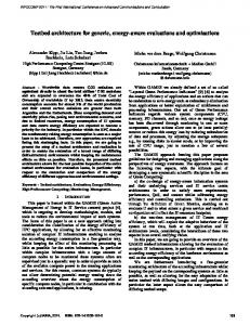
FASSI 2015 : The First International Conference on Fundamentals and Advances in Software Systems Integration
A Novel Three-layer Architecture for Information System Integration
Kamrul Ahsan
Juha-Miikka Nurmilaakso
School of Information Sciences, University of Tampere Integration Excellence, HiQ Finland Oy Tampere, Finland e-mail:
[email protected]
Integration Excellence, HiQ Finland Oy Espoo, Finland e-mail:
[email protected]
Abstract— The purpose of Information System Integration (ISI) is to streamline business processes by synchronized or asynchoronized completion of a series of steps. Integration architects use the so called “integration layer” as a methodology to accomplish such tasks. To date, in the literature, three kinds of layer mechanisms are reported: No (Point-to-Point), One (Message Brokers), and Two (Message Bus). Although these three kind of layer types can solve most of the integration challenges, among them there are both design and run-time quality challenges. In this paper, a new type of layering, named “Three integration layers” is introduced to improve the quality of the integration solutions. Also, this paper argues that new integration layers can be used for ISI projects to improve IS integration quality.
materialized at the global level. This approach is generally used in data warehouses and it does not have any unstructured information [1]. In the conceptual model, a layer-based architectural pattern is used in ISI implementation projects [2]. Currently, there are three ISI layer architectures available namely No integration layers or point-to-point, one integration layer or message brokers, and two integration layers or clients / servers or Enterprise Service Bus (ESB). In general, the No integration layer or point-to-point integration, data flows directly from system to system. A point-to-point connection ensures that only one receiver receives a particular message [4]. One integration layer or message brokers (also referred to as hub-and-spoke architectural style) receive messages from multiple destinations, determine the correct destination and route the message to the correct channel. Finally, the two or Client/Server or service bus integration is the integration systems that are comprised of two logical parts: a server that provides the integration services and a client that requests services of the server. Together, they form a complete integration system with a distinct division of responsibility. Due to the complexity of IS, constant changes of business processes, technological advancement and cloud computing, current layer-based architectural pattern of ISI has shortcoming in terms of integration quality, especially quality aspects such as design and run-time attributes. Table I outlines some of the current challenges of various layerbased architectural patterns. In order to overcome some of the quality attributes of the current integration layering based architectural challenges, a new type of layer named three-layer or router-based layer pattern is introduced in this paper. The routing layer or router works as an orchestration, which is configurable. The router utilizes a content-based publish-and-subscribe pattern with filters and self-correlations to support integrations between the receiving and sending layers. This integration takes place by wrapping a source or target message as a payload in a routing-specific envelope. The architecture can be implemented as a standalone application using Web Services (WS) or by using any modern ESB (For example, Microsoft BizTalk).
Keywords-information system integration; layer architecture; router.
I.
INTRODUCTION
Information System (IS) is the combination of information technology, data, personnel and associated business functions which interact to generate information and creates an information resource which assists the organization to achieve its business goals. To accomplish its business goal, organization uses multiple IS, which leads to multiple information source. Information System Integration (ISI) is the sets of tools and methodology that allows various IS to interact each other to create aggregate business value, reduce heterogeneity of the IS, allows to adopt of new information technology (IT), facilitate e-commerce, improve business efficiency, allows managers in enhancing performance, increases complete knowledge of the enterprise and its customers in decision making process [1] [7] [8]. The ISI concept is multi-faceted and multidimensional. In terms of information integration, the architecture of the ISI can be – use either a virtualization approach or a materialization approach [1]. In the virtualization approach, the data resides in the individual data sources and the virtualization layer is defined as a virtual schema which has attributes from all the data sources. When a user query defined on the virtual schema is received by the system, it determines the relevant sources to be queried and then breaks down the query into sub-queries for the different sources [1]. On the other hand, the materialization approach, the data is
Copyright (c) IARIA, 2015.
ISBN: 978-1-61208-448-0
7
FASSI 2015 : The First International Conference on Fundamentals and Advances in Software Systems Integration
TABLE I. INTEGRATION PATTERNS AND THEIR CHALLENGES [5] [6]
Patterns No-layer
One-layer
Two-layer
Challenges Number of connections increases with respect to number of applications Tight coupling Less extendable Limited re-use Less scalable Rigid in terms of agility Limited to technology (Technology constraint) Single point of failure High cost Excessive use of network resources Unable to integrate applications without enforcing a common interface Cannot allow each application to initiate interactions with several other applications The cost of adding or removing applications increases as an integration solution grows Unable to only send messages to the applications that are interested in receiving the messages without knowing the identities of the receivers
The proposed layer-based integration architecture tries to solve some of the quality challenges of ISI. In order to show the area of the IS, where this new artifacts fits, Section II contains two useful theory of ISI: interoperability and integration - with brief narrative descriptions and relevancy with the proposed method. Existing three types of layerbased integration architecture have been briefly presented and compared in the Section III. The proposed new type of integration architecture is shown in details in Section IV with comparisons with two layer-based architecture. In Section V, four kinds of layer-based integration architecture has been discussed in relation to some of the ISI related quality attributes. Finally, Section VI contains the concluding remark. II.
BACKGROUND
Today organizations use multiple software or information systems to operate their day to day business operations. In order to achieve aggregate business value, these IS need to be integrated. Unlike software integration, which is the practice of assembling a set of software components/subsystems to produce a single, unified software system, ISI can be defined as combination of system, software and tools integration for modernizing, consolidating, and coordinating the computer applications in the organization [9]. The architecture of ISI is layered-based due to the fact that IS architecture comprises of: information, application and technology. Thus, layer-based design patterns are suitable for logic interaction. Integration in IS can occur at the data, method, interface, portal, and process level and such variety basically represents how the application “sees” integration [9]. To address such variety, Hohpe and Woolf [3] have divided the integration types as: Business Process Integration, Messaging based, Remote Procedure Invocation (RPC), Shared Database, Managed File Transfer (MFT), User-Interface based, and Data integration.
Copyright (c) IARIA, 2015.
ISBN: 978-1-61208-448-0
Another important characteristic of ISI architecture is messaging. Regardless of integration type, the exchange of data is common in all ISI levels [9]. Data (for example, orders or invoices, not integers or strings) is the primary means to integrate multiple applications so that they work together by exchanging information without loss of accuracy. ISI uses messaging techniques to transfer packets of data frequently, immediately (synchronously), reliably, and asynchronously using customizable formats [3]. ISI uses a special filter named message router, which consumes a message from one message channel and republishes it to a different message channel depending on a set of conditions [3]. Message routers are categorized into the following groups: simple routers which are variants of the message router and route messages from one inbound channel to one or more outbound channels, composed routers that combine multiple simple routers to create more complex message flows, and finally the architectural patterns which describe architectural styles based on message routers [3]. Furthermore, following message routing patterns are described by [3]: Content-Based Router, Message Filter, Dynamic Router, Recipient List, Splitter, Aggregator, Resequencer, and Composed Message Processor. Finally, clear understanding of the term integration and interoperability is needed when systems needs to be integrated. The integration is the practice of assembling a set of software components/subsystems to produce a single, unified software system that supports some need of an organization [15]. On the other hand, interoperability is the ability for two systems to understand one another and to use functionality of one another [16]. The word ‘‘inter-operate’’ implies that one system performs an operation for another system. Thus by definition, two integrated systems are inevitably interoperable; but two interoperable systems are not necessarily integrated [16]. For example, a good analogy could be the relationship between Video Cassette Recording (VCR) and Television (TV). A VCR and a TV bought in the same country are interoperable. One just needs to connect them together. However, a VCR bought in the US and a TV bought in the UK may need the special signal conversion services of an NTSC/PAL converter in order to integrate them. III.
LAYER-BASED INTEGRATION ARCHITECTURE
In this Section, traditional layer-based integration architectures have been described and compared. To visualize and count number of interactions needed by each integration types to implement a business process, “order creation” [17] business process is used. It is sales related or more specifically Sales Order (SO) business process where client creates a SO from a portal to Enterprise Resource Planning (ERP) system. The business process also needs to check whether subjected client exists in the Customer Relationship Management (CRM) system.
8
FASSI 2015 : The First International Conference on Fundamentals and Advances in Software Systems Integration
A. No integration layers: point-to-point A point-to-point integration (Figure 1) ensures, that only one receiver receives a particular message [5]. For this to work, the sending system must know the location of the receiving node. The sending system often must translate the message into a format that the receiving system understands.
ERP
SCM
Integration Layer ERP
SCM
CRM
Portal
Figure 3. One integration layer-based ISI
Portal
CRM
Figure 1. No integration layer-based or direct ISI
Although it is easier, less costly and requires less upfront work to implement point-to-point integration, the method is not suitable when a large number of applications need to be integrated. The number of point-to-point integrations basically increases as follows: N*(N – 1) / 2. In this calculation, N is the number of applications involved in the integration [5]. Figure 2 shows message flows among various IS to create a SO business process. Note that, the CustomerPortal which is responsible for integrations may demand expensive software customization.
CustomerPortal
ERP
It is a physical component that handles the communication between applications [10]. Instead of communicating with each other, applications communicate only with the message broker. An application sends a message to the message broker, providing the logical name of the receivers. The message broker looks up applications registered under the logical name and then passes the message to them. Figure 4 shows message flows among various IS to create a SO business process using one layerbased integration.
CRM
Prepare SO
Prepare SO Response Check Customer
Check Customer Response Process SO
Process SO Response
Figure 4. Sales order business process using message broker integration Figure 2. Sales order business process using point-to-point integration
B. One integration layer: message broker A message broker can receive messages from multiple sources, determine the correct destination and route the message to the correct channel (Figure 3).
Copyright (c) IARIA, 2015.
ISBN: 978-1-61208-448-0
9
FASSI 2015 : The First International Conference on Fundamentals and Advances in Software Systems Integration
TABLE II. COMPARISIONS BETWEEN ONE-LAYER AND NO-LAYER
Maintainability
Standardization of data, process and technology
Add, update or delete integration process Process monitoring and alerts
Scalability
No-layer Design qualities It is required that business process and data model as well as technology must be included inside both the source and target system's integration interface so that the integration between systems works. This requires customization both in source/target system increasing the number of the interfaces. It is challenging to change business processes or other integration related changes in source/target system and in their interfaces when required.
Fewer of the source / target system are able to provide an overall picture of the progress of the business processes as control of the feature depends of the subjected system.
Run-time qualities Less saleable and number of connections increases with respect to number of applications.
C. Two integration layers: clients and servers / service bus Two integration layer (Figure 5) or client/server or ESB or a message bus allows applications to connect through a logical component and it specializes in transporting messages between applications [11]. A message bus contains three key elements: A set of agreed-upon message schemas, a set of common command messages [3], and a shared infrastructure for sending bus messages to recipients.
Source
Locking, Reporting
Source
One-layer No such requirements thus the number of interfaces reduces significantly.
It is possible to modify, enrich, route and operational logic in the integration interfaces without changing the source/target system. Since all the processes use a single platform, it is relatively easy to monitor business processes and integration of technical performance, as well as to obtain consistent alarms faults using custom or built-in custom tools. The integration substrate may be nodes, of which one or more are active at a time, and which are linked to one another either directly or with the help of the integration database. Thus, one layer architecture can provide a number of options for scalability. Server Service
Target
Server Service
Target
Server Service
Target
Server Service
Target
Client Service
Client Database
Client Service
Figure 5. Conceptual model of two integration layer-based ISI
In two layer integration, an application that sends a message no longer has individual connections to all the
Copyright (c) IARIA, 2015.
ISBN: 978-1-61208-448-0
10
FASSI 2015 : The First International Conference on Fundamentals and Advances in Software Systems Integration
applications that must receive the message. Instead, the application merely passes the message to the message bus, and the message bus transports the message to all the other applications that are listening for bus messages through a shared infrastructure. Likewise, an application that receives a message no longer obtains it directly from the sender. Instead, it takes the message from the message bus. In effect, the message bus reduces the fan-out of each application from many to one [11]. The two integration layer-based ISI is capable of scaling pervasively across enterprise applications, regardless of physical location and technology platform [12]. Any application can plug into an ESB network using a number of connectivity options, and immediately participate in data sharing with other applications that are exposed across the bus as shared services. This is why the ESB is often referred to as an integration network or integration fabric [12]. Figure 6 shows message flows among various IS to create a SO business process using two layer integration. CheckCustomerServerService
PortalSOClientService
CustomerPortal
PrepareSOServerService
Finally, Table III compares some of the ISI quality attributes between two-layer and one-layer. IV.
PROPOSED THREE-LAYER ARCHITECTURE A
The conceptual model of the proposed three layer-based integration is composed of three layers namely receiving, routing and sending (Figure 7).
One-way Receiver Service
Source
One-way Sender Service
Target
Two-way Sender Service
Target
Router Service Two-way Receiver Service
Source
Configuration, Locking, Reporting
Router Database
Figure 7. The conceptual model of three layer-based ISI
ERP
ProcessSOServerService
CRM
Portal SO Canonical Order Prepare SO
Prepare SO Response Canonical Order Response Canonical Order
Check Customer Check Customer Response
Canonical Order Response Canonical Order Process SO Process SO Response Canonical Order Response
Portal SO Response
Figure 6. Sales order business process using two layer integration
TABLE III. COMPARIEIONS BETWEEN ONE AND TWO LAYER
One-layer Design qualities It does not contain any re-useable artifact
Reusability
Flexibility
Data format
Copyright (c) IARIA, 2015.
Run-time Qualities It does not support data modelling functionality.
ISBN: 978-1-61208-448-0
Two-layer Server layer reusable.
(component)
services
are
It uses a CDM. In addition, applications can use adapters, so it is not mandatory all applications use the same data format.
11
FASSI 2015 : The First International Conference on Fundamentals and Advances in Software Systems Integration
Begin/ end
Constructing steps of sequence or locking fails for two-way receiver but response succeeds
More steps to route in sequence, no error occurs and step continues sequence
One-way receiver or response to two-way receiver fails
Response to two-way receiver succeeds
Two-way Receiver
Two-way Sender
Start
Prepare
Route
Check
Finish
End
One-way Sender
One-way Receiver
Begin
Constructing steps of sequence and locking succeed
No more steps to route in sequence, error occurs or step interrupts sequence
Figure 8. Details architecture of the three layer-based ISI
Compared to the Client Interface Layer (CIL) – Concept Layer (COL) architecture, which has two layers and CIL components integrate the external (party) systems and COL components integrate internal systems, the router architecture does not make such a distinction (Figure 8). Figure 9 shows message flows among various IS to implement SO business processes using router-based integration. CheckCustomerSenderService
RouterService
CustomerPortal
PrepareSOSenderService
PortalSOReceiverService
can choose how to use the sending layer. In addition, the router can employ time-based locking to ensure that only one router instance handles the same object (e.g., order or invoice etc.) at the sending layer. There are four kinds of routers:
ERP
ProcessSOSenderService
CRM
Portal SO Router Envelope (Canonical Order)
Router Envelope (Canonical Order) Prepare SO
Prepare SO Response
Router Envelope (Canonical Order Response) Router Envelope (Canonical Order)
Check Customer Check Customer Response
A non-locking one-way router receives a request envelope but does not send a response envelope or lock the object related to the envelope. A non-locking two-way router receives a request envelope and sends a response envelope but does not lock the object related to the envelope. A locking one-way router receives a request envelope, locks, relocks and unlocks the object related to the envelope but does not send a response envelope. A locking two-way router receives a request envelope, locks, relocks and unlocks the object related to the envelope and sends a response envelope.
Router Envelope (Canonical Order Response) Router Envelope (Canonical Order) Process SO Process SO Response
Router Envelope (Canonical Order Response) Router Envelope (Canonical Order Response) Portal SO Response
Figure 9. Sales order business process using router-based integration
A. Router The routing layer or router is an orchestration, which is configurable by the RoutingDB (Name of the database) database. The router utilizes a content-based publish-andsubscribe pattern with filters and self-correlations to support integrations between the receiving and sending layers. This integration takes place by wrapping a source or target message as a payload in a routing-specific envelope. Applying the XPath (It is a language for addressing specific parts of an XML document) rules to the envelope, the router
Copyright (c) IARIA, 2015.
ISBN: 978-1-61208-448-0
B. Receiver layer The receiving layer or receivers enable one-way and twoway integrations with external and internal source systems. The one-way/two-way receiver is an orchestration or a oneway/request-response receive port with a map and, if necessary, a custom pipeline. The receiver receives a source message using a source protocol, transforms the source message to an envelope and sends this envelope to the router. The two-way receiver also receives a response envelope, transforms it to a response message and sends the message to the source system using the source protocol. It is possible but not recommended, that the one-way receiver sends the response message or the two-way receiver does not send the message.
12
FASSI 2015 : The First International Conference on Fundamentals and Advances in Software Systems Integration
C. Sender layer The sending layer or senders enable one-way and twoway integrations with external and internal target systems. The one-way/two-way sender is an orchestration or a oneway/solicit-response send port with a map and, if necessary, a custom pipeline. The sender receives an envelope, transforms this envelope to a target message and sends this target message to the target system using a target protocol. The two-way sender also receives a response message using the target protocol, transforms it to a response message and
sends the message to the router. It is possible but not recommended that the one-way sender receives the response message or the two-way receiver does not receive the message. Finally, Table IV compares ISI related quality attributes between router-layer and two layer integration pattern.
TABLE IV. COMPARISIONS BETWEEN TWO AND THREE LAYER
Two-layer
Reusability
Flexibility
Three-layer Design qualities Server layer (component) services are reusable. Both receiver and sender layer (component) services are reusable Run-time Qualities It does not have such functionalities. Router layer (composite) services are flexibly configurable and provide reusable locking and monitoring functionalities for process integration. V.
DISCUSSION
Layered architecture is widely used architectural patterns in software design practice. It helps to structure applications that can be decomposed into n groups of subtasks in which each group is at a particular level of abstraction with welldefined interfaces [2]. Proposed new ISI router-based layer pattern improves quality and brings more flexibility to the integration architect over existing no, one and two layeredbased ISI architecture. Modularity Parnas [13] defined information hiding as an approach to devising modular structures for software designs. The purpose of modular design is to decouple design decisions that are likely to change so that they can be changed independently and at the same time to improve the reusability and maintainability. Maintainability refers to the ease with, which a software system or component can be modified to correct faults, improve performance or other attributes, or adapt to a changed environment [14]. On the other hand, reusability is the degree to which a software module or other work product can be used in more than one computer programs or software systems [14]. In the followings paragraphs, the proposed three layer-based ISI architecture is compared with other existing layer-based architectures with respect to maintainability and reusability. First of all, at the center of modular design is the module it-self where business processes and integrations are mostly formed by independent modules. They are better known as
Copyright (c) IARIA, 2015.
ISBN: 978-1-61208-448-0
services or producers/consumers. In such scenario, modules are made of standardized interfaces and functionalities. In addition, in order to communicate with other modules, interfaces must be compatible and follow standard data structure. The Canonical Data Model (CDM), which is sufficiently comprehensive and independent regardless of source and target systems, can be used for this purposes. It provides additional level of indirection between application's individual data formats. If a new application is added to the integration solution only transformation between the CDM has to be created, independent from the number of applications that already participate [3]. Another important requirements of the modularity is that orchestration, data structures and transformations required by the integration are not tightly coupled, but they are loosely coupled in the form of individual packages. In general, orchestration is integration specific, while some of the data structures and modifications may be generic. Since no or direct ISI forms “tightly coupled” connections between components or source/target IS (Figure 1), it is impossible to design such integration using modular design principles. Thus, such integration is difficult to maintain. In addition, both interfaces and functionalities of direct integration often cannot be reused. Two- and three-layer architectures are modular. As Figure 10 suggests, these approaches do not exclude each other and do not forbid use of orchestration which is an integral part of integration artifacts. For example (Figure 10), when some changes occur in the basic information of system A, then Master Data Management (MDM) and systems B, C, D will also be immediately updated. In addition, the MDM solution can provide details of the change for the basic information. If update procedure is successful in all relevant systems, change of basic
13
FASSI 2015 : The First International Conference on Fundamentals and Advances in Software Systems Integration
information in MDM solution can be confirmed. Otherwise changed but unconfirmed basic information can be updated in the A, B, C and D systems in a batch mode from the MDM solution. Note that, in this example, A and D systems only support asynchronous interfaces, whereas B and C systems support synchronous data transfer.
Figure 10. Example of layer-based ISI using basic orchestration
transfer data with the source system, modify and enrich data in source system and the internal data structure for the data between the content and the distribution of the data content of the COL services. CIL-service can be of a stateless or state-full. On the other hand, COL-service is responsible for modifications and enrichment of the information content in the target system as well as transfer information within the target system. However, regardless of integration platform, the information transformation between CIL- and COLservices is done either using request-response or publishersubscriber mechanism. The three-layer architecture proposed in this paper is composed of receiver-service, router, and sender-service (Figure 12). Router has two versions which can serve as both one- and two-way receiver-services. Sender and receiver service support the internal data structure, and based-on such mechanism router service decide which router versions to use.
Two-layer architecture consists of CIL- and COLservices (Figure 11). The purpose of CIL-service is to
A Update Basic Data CIL
A
B Update Basic Data COL
MDM Update Basic Data COL
D Update Basic Data COL
C Update Basic Data COL
MDM
MDM Basic Data Updated COL
C
B
D
Figure 11. Detail example of two layer-based ISI
Copyright (c) IARIA, 2015.
ISBN: 978-1-61208-448-0
14
FASSI 2015 : The First International Conference on Fundamentals and Advances in Software Systems Integration
A
One-way Router
A Update Basic Data Receiver
B Update Basic Data Sender
MDM Update Basic Data Sender
D Update Basic Data Sender
C Update Basic Data Sender
MDM
MDM Basic Data Updated Sender
C
B
D
Figure 12. Detail example of three layer-based ISI
Figure 8 presents the behavior of the router service. The router server receives envelopes from one-way receivers, while it interacts with two-way receivers by request and response envelopes. To lock an object such as a sales order or to report its identity and state, the router service must create the object based to the envelope and store it into the database. The router service can lock and unlock a given object so that only one router service instance per this object can be performed at the same time. The router service instance has a sequence which consists of steps. Evaluating configured rules against the envelope determines which step the router service instance should perform next in the sequence. A step determines how the router service sends the envelope to a one-way sender or interacts with a twoway sender by the request and response envelopes. The router service can maintain the object state according to these response envelopes. Router-service, two-way communication and SenderReceiver with the services take place between CIL- and COL services. One-way service, this data is to be either oneway or publisher-subscriber relay model of integration depending on the substrate. VI.
CONCLUSIONS
Due to multiple known and unknown components (business and technology) both in-source, integration platform and destination systems, layer-based architecture is
Copyright (c) IARIA, 2015.
ISBN: 978-1-61208-448-0
the right architectural fit for ISI. Although all the layerbased integration methods have advantages and disadvantages over one another, in relatively complex and routine integration projects, various quality attributes need to be considered. In this paper, both existing and proposed layer-based ISI architecture have been compared in terms of design and run-time quality category. Among all ISI architecture types, the proposed three layer-based or router based architecture provides more modularity and flexibility. Even though layer-based architecture also directly involve other quality category such as system and user qualities in the ISI, comprehensive comparisons of such quality categories are the natural direction for the future work of the proposed three-layer based ISI. The authors are carrying out further research including an empirical study to compare these architectures using a real life industrial business Usecase. ACKNOWLEDGMENT Authors would like to gratefully and sincerely thank Dr. Eleni Berki (University Of Tampere) and Elli Georgiadou (Middlesex University, UK) for the discussions, reviewing the paper and for their valuable comments during the writing process. In addition, authors also like to take the opportunities to thank HiQ Finland Oy and University Of Tampere for being very co-operative and supportive to carry out this research activities.
15
FASSI 2015 : The First International Conference on Fundamentals and Advances in Software Systems Integration
REFERENCES [1]
[2]
[3]
[4]
[5]
[6]
[7]
[8] [9]
M. Mohania and M. Bhide,“New trends in information integration,” ICUIMC '08 Proceedings of the 2nd international conference on Ubiquitous information management and communication, 2008, pp. 74-81 F. Buschmann, R. Meunier, H. Rohnert, P. Sommerlad, and M. Stal, “Pattern-Oriented Software Architecture, Volume 1, A System of Patterns,” John Wiley and Sons, 2000, ISBN-10: 0471958697 G. Hohpe and B. Woolf, “Enterprise Integration Patterns: Designing, Building, and Deploying Messaging Solutions,” Addison Wesley, Oct. 2006, ISBN : 0-321-20068-3 Microsoft patterns and practices, integration patterns, June. 2004. [retrieved: May, 2015]. Available from : https://msdn.microsoft.com/en-us/library/ff647958.aspx#intpattch05_pointtopointconnection W. Roshen, “SOA-Based Enterprise Integration: A Step-by-Step Guide to Services-Based Application Integration,” The McGraw-Hill, 2009, ISBN: 978-0-07-160553-3 Microsoft patterns and practices, Integration Topologies, June. 2004. [retrieved: May, 2015]. Available from : https://msdn.microsoft.com/en-us/library/ff647958.aspx#intpattch05_broker C. S. Chapman and L. Kihn, “Information system integration, enabling control and performance,” Elsevier, Accounting, Organizations and Society Volume 34, Issue 2, Feb. 2009, pp. 151– 169, ISSN: 0361-3682 K. Ravi and M. Robinson, “E-business 2.0: Roadmap for Success,” Addison-Wesley, 2001, ISBN 0201721651 A. Vasconcelos, M. Mira da Silva, A. Fernandes, and J. Tribolet, “An information system architectural framework for enterprise application
Copyright (c) IARIA, 2015.
ISBN: 978-1-61208-448-0
[10]
[11]
[12] [13]
[14]
[15]
[16]
[17]
integration,” System Sciences, 2004. Proceedings of the 37th Annual Hawaii International Conference on , vol., no., Jan. 2004, pp.9, doi: 10.1109/HICSS.2004.1265551 Microsoft patterns and practices, Message broker, June. 2004. [retrieved: May, 2015]. Available from : https://msdn.microsoft.com/en-us/library/ff648849.aspx Microsoft patterns and practices, Message bus, June. 2004. [retrieved: May, 2015]. Available from : https://msdn.microsoft.com/enus/library/ff647328.aspx D. Chappell, “Enterprise Service Bus,” O'Reilly, Jun. 2004, ISBN 0596-00675-6 D. L. Parnas, “On the criteria to be used in decomposing system into modules,” Communications of the ACM, Vol. 15, No. 12, Dec. 1972, pp.1053–1058. IEEE Std 610.12-1990, “Glossary of software engineering terminology,” in software engineering standards collection, IEEE CS Press, Dec. 1990, doi: 10.1109/IEEESTD.1990.101064 V. Stavridou,“Integration in software intensive systems,” Journal of Systems and Software, vol. 48, Issue 2, Oct. 1999, pp. 91–104, doi:10.1016/S0164-1212(99)00049-7 D. Chena, G. Doumeingtsb, and F. Vernadatc,“Architectures for enterprise integration and interoperability: Past, present and future,” Computers in Industry, vol. 59, Issue 7, Sep. 2008, pp. 647–659, doi:10.1016/j.compind.2007.12.016 J. Nurmilaakso and J. Kauremaa,“Business-to-business integration: Applicability, benefits and barriers in the telecommunications industry,” Computers in Industry, vol. 63, Issue 1, Jan. 2012, pp. 4552, doi:10.1016/j.compind.2011.10.006
16