CIB W78 2008 International Conference on Information Technology in Construction Santiago, Chile
A CONTEXT-ADAPTIVE BUILDING INFORMATION MODEL FOR REAL-TIME STRUCTURAL ANALYSIS IN A DISASTER MANAGEMENT SYSTEM Rüdiger SCHÜTZ1, Thomas Bernoulli1, Thomas Wießflecker1, Ulrich Walder2 1
Research Assistant 2 Professor Graz University of Technology, Austria
[email protected]
ABSTRACT In case of disasters in urban areas it is important to immediately gain precise information about the constructional environment in order to react appropriately. Information can be gathered from Computer Aided Facility Management (CAFM)-, Computer Aided Design (CAD)- and Geographic Information Systems (GIS)-Applications but their effectiveness depends on the preparation of the data for the special needs in extraordinary situations. A major challenge is the integration of real-time data from sensors in the building and from the equipment used by the rescue forces on site. At the Institute of Building Informatics a Computer Aided Disaster Management System (CADMS) is under development which is based on an enlarged ifcXML model. The system allows for the interaction of building data with static and mobile sensors, and can be used for indoor positioning of the rescue forces. A simplified, real-time adaptive static model will be used to estimate the danger of structural collapse. The rescue forces will be equipped with head-mounted displays (HMDs) and be able to interact with the application by voice. The tracking of the rescue forces is performed by inertial and magnetic sensors. These sensors are constantly calibrated according to the surrounding “intelligent” building data. KEYWORDS building model, sensors, real-time structural analysis, indoor positioning, speech enabled user interface
1. INTRODUCTION Today information about buildings is usually gained from traditional floor plans and maps which are part of CAFM-, CAD- or GIS-Systems. The first one is state-of-the-art for today’s large real estates. Their databases need to be prepared for the special requirements in extraordinary situations to increase their effectiveness. In particular the ability to integrate data from sensors and data added by the user (i.e. rescue forces) is an essential enhancement for the serviceability of the plans in case of emergency situations. During situations like fires, floods or terrorist attacks various information is collected by the rescue forces. With this information, the difficulties of overviewing the scene as a whole can be reduced and therefor appropriate response strategies can be developed. Furthermore an efficient coordination of the whole rescue operation can be developed upon these data. Most of those information concern the location of objects (like exits, stairways) but any other semantic information (destroyed fire extinguishers, hazardous areas, structural element collapse) can be included as well. Especially in public large buildings like shopping malls or underground railway stations precise information about the structural behaviour is important. This is essential for decisions like whether or not to evacuate an area within the building. Though common rescue forces are experts with lots of experience in their field of profession, they usually do not have enough knowledge as well as information to carry out a structural analysis. Therefore a context-sensitive Building Information Model (BIM) has been developed and its data will be linked with a finite element program enabling an immediate, real-time verification of the structural
CIB W78 2008 International Conference on Information Technology in Construction Santiago, Chile
behaviour. This BIM is a new approach to integrating structural data for a real-time analysis in an emergency command system. This system is based on a CAFM-database and an IFC-based architectural model. Further, dynamic data are added to the system. These data are gained by either sensors within buildings or mounted on persons or that are “manually” provided by the on-site staff. With this BIM, the impact of changes concerning the structural elements of a building can be estimated and it can therefore contribute to reducing the risks in case of extraordinary incidents. Though the project is still under development this paper shows the up-to-date outlines of the CADMS with a focus on the BIM, the real-time structural analysis and the approaches to designing a voice operated user interface for this application. Further, first implementations will be presented and the challenges for future work will be discussed.
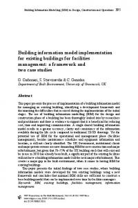
2. GENERAL SYSTEM ARCHITECTURE This paper focuses on some specific parts of the system used during a case of emergency. The system itself consists of five components: the building model, the position estimation, the position verification and correction, the user interface and the communication. All those parts are shortly illustrated in this paragraph. The system requires floor plans supplemented with additional data that include transitions between rooms and floors as well as room boundaries for example. Augmenting floor plans with information on semantics are created using a commercial Computer Aided Facility Management (CAFM) system. The floor plans are tagged with additional information and converted into an XML document. This XML document is locally stored on every device allowing for autonomous navigation and fast data access. In our system real-time data is gathered by inertial navigation and positioning based on Inertial Measurement Units (IMUs). They work without fix or temporary infrastructure. The position determination is based on a position defined as starting point and ongoing movement measurements [Glanzer 2007]. On device start-up the current location has to be determined. Since the results of the inertial navigation are not accurate enough for indoor positioning in extraordinary situations [Beauregard and Haas 2006], a novel approach is used for the position determination. To accomplish this task, information on semantics like the exact position of the entrances to the building, doors, fire extinguishers is used. Once initialised a verification and correction module permanently corrects the position with information about landmarks included in the BIM. This assures the correctness of the position data. The position estimation reads raw sensor data and therewith computes the position coordinates. Once computed, a position is verified and corrected if necessary. Each instance of raw position information is examined and checked against information about the building. The verification and correction process is based on the tagged floor plans and is designed to require as little user interaction as possible. By exploiting information on semantics, physically impossible measurement results can be detected and partly corrected. By comparing consecutive data and knowing the location of room transitions, the position of on-site staff entering neighbouring rooms through walls can be corrected (Fig. 1). Thus, re-positioning can be carried out automatically without asking the user for interaction, if the information about the building is dense enough and the measurement inaccuracy is not too high. Otherwise, the user has to communicate his current position to the CADMS. It is possible for the user to define his position by giving information related to his current position, like closely located fire extinguisher or similar. This information is analysed by the system and the position can be corrected.
CIB W78 2008 International Conference on Information Technology in Construction Santiago, Chile
Figure 1: Correction of imprecise position measurement results exploiting information from the BIM
The output of the verification and correction procedure is comprised of the corrected position data which is transmitted to other network nodes. To communicate the location of the mobile units among themselves and to the control room, special mechanisms based on the IEEE-802.11 Standard (Wi-Fi) are fused to build up an optimised communication network. The BIM-data is linked with a finite element (FE) program. With the support of an implemented algorithm all detected critical changes concerning structural elements automatically initiate an analysis of the structural behaviour. This enables the rescue forces to develop operation strategies like distributing alert messages to other teams or initiating the evacuation of the building. Finally there are two user interfaces. A conventional one to be used on computer terminals equipped with a screen and a pointing device (mouse, touch screen) and one to be used on head mounted displays with speech enabled controls for the staff on-site.
CIB W78 2008 International Conference on Information Technology in Construction Santiago, Chile
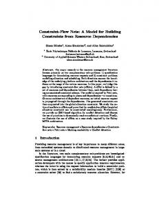
3. GAINING INFORMATION FOR A BUILDING INFORMATION MODEL The BIM data for the CADMS are stored in the XML format and can be gained either by extracting them from a CAFM system or by converting traditional CAD or GIS data. Therefore the graphic input module of the CAFM system in use has been enlarged to add context-sensitive information interactively, for example for rooms, doors, staircases and structural analysis. BIM data could be also gathered from an enlarged ifcXML model. The Industry Foundation Classes (IFC) data model is a neutral and open specification and it is the state of the art modelling language for BIM. Unfortunately, the IFC-standard has not yet been widely introduced in practice, especially in the building documentation. This will not change in the near future because of the large effort needed for redefining the 3D-models of older buildings. In fact, 3D-data are not really necessary in disaster management. A 2½D overview of the situation is more suitable for the command and deployment of rescue forces. It requires floor plans with their proper orientation in space and the ability to position several of them at the same time on the command console or the HMD of the rescuers. A special challenge poses the integration of sensor data and building information model data. Modern buildings are equipped with multiple real-time systems such as fire protection, admission control, building automation systems. Important information can be gained from these sources as long as they are still in working order. Unfortunately these systems are usually based on own building models and are directly visible for real-time evaluations and rarely in CAFM systems. CADMS gathers current building-sensor data over interfaces and represents them as space attributes in the data base of the BIM. Additional real-time data are those gathered from the IMUs and the building’s status information collected by the emergency forces. These data is combined with those mentioned before in the BIM as well, as shown in Fig. 2. Thus, the CADMS can handle status information collected by the action forces and immediately highlight blocked routes, the location of hazardous substances, areas with trapped people inside, smoke or gas alarm or leakage of dangerous goods in the floor plans. Our proposed building information model is context-adaptive, which means that the model can be adapted during the deployment according to possible influences from the environment. Due to its hierarchical and object-oriented design it is not complicated to change the attributes of the elements in the model. If the rescuer on-site faces an impassable, door he can communicate this observation to the CADMS, which immediately changes the settings in the BIM and the structural analysis data set if necessary. From this time on, all the functions of the CADMS will work with the adapted model.
4. REAL-TIME STRUCTURAL ANALYSIS IN DISASTER MANAGEMENT Creating a structural model from an IFC-based architectural model is described in the paper of Deng and Chang (2006) and the primary prerequisite is a 3D architectural model. As mentioned before, such data models are currently not widely available in building documentation. A direct extraction of a finite element model from an IFC-based architectural model is not suitable for other reasons as well. The aggregation with structural data not included in the architectural model, like loads, load superposition and design rules, is necessary. Automatically derived models do not correlate very well with the real load bearing behaviour. Furthermore automated detection and correct modelling of structural elements like hinges, elastic supports is very difficult.
CIB W78 2008 International Conference on Information Technology in Construction Santiago, Chile
Building Information Model (BIM)
static data
preparation of CAFM-data
integration
IMUs
dynamic data
rescue forces
origin: local or via network static sensors within buildings
FIGURE 2: COMBINING CAFM AND REAL-TIME DATA FOR INDOOR POSITIONING
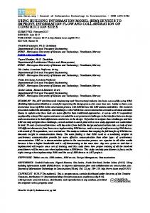
Structural models as described in [Romberg et al. 2004] composed completely of 3D-volume elements are not useful either. The computations last too long and the results are difficult to interpret. In case of an interrupt in communication between the command centre and a deployed team, the structural analysis will have to be performed on the local mobile device with limited computing power and data storage capacity. Therefore in the CADMS it is intended to store a simplified static model with all the necessary information on sections, materials, loads and load superposition in the format of a commonly used finite element program (Fig. 3). At the moment the program FLASH [Walder 1979] is used.
3 destroyed Colums → removed elements
Figure 3: Simplified collapse model with removed elements
CIB W78 2008 International Conference on Information Technology in Construction Santiago, Chile
In addition to an interactive graphical input FLASH offers a format free input language based on a philosophy quite similar to XML. The structural bearing elements can be modelled by beam, plate and shell elements. Well-defined numbers are linked as XML-elements to the corresponding elements in the BIM. This solution can be realised with almost every FE-program providing numerical input. Though this procedure requires a large effort in redefining or at least linking an existing static model to the BIM, but it should be taken into account especially for high-risk buildings. When rescue teams or local sensors detect the collapse of a bearing element, the structural model is immediately adapted and recalculated. This is realised by the implementation of a decision tree. It is started automatically every time a change of the structural model within the BIM occurs. In each case this algorithm decides whether or not to start a structural analysis. Furthermore it can update the BIM in other parts of the system if necessary. A simple scenario where more than one attribute is affected by a new input, is the notification of a collapsed wall. Logically this initially affects the accessibility (potential new way to enter neighbouring rooms) and the structural model. Though, as shown in Fig. 4, not only these attributes are affected. If the wall was a supporting one, a structural analysis has to be performed which could lead to changes in the accessibility as well as the representation model. structural element collapsed
change structural model
is wall a supporting one?
yes
change accessabilities
yes
no
no change graphical representation
other structural element threaten to collapse?
perform structural analysis
Figure 4: Sequence of actions in the system triggered by the knowledge of a collapsed element
Fig. 5 shows the implementation of a beam in BIM data by means of ifcXML [Nisbet and Liebich 2007] and the reference to the corresponding entity in the finite element program.
5. USER INTERACTION The traditional user interface of the CADMS provides a conventional desktop layout with menu items to navigate on floor plans to view the position of different emergency crews, enter alarm messages to be distributed, and command and control functions. The interface used by the forces on-site is more challenging. It has to be tailored for the visualisation on HMDs and operation by voice commands as it must not interfere on the one hand but make information easily available for the on-site staff on the other hand. An
CIB W78 2008 International Conference on Information Technology in Construction Santiago, Chile
295H6hv1z5T Element4931 ReferenceToFE BEAM61
Figure 5: Automated adaption of the Finite Element input from BIM data HMD with see-through functionality ensures that the additional equipment does not interfere with the activities of the rescue teams. Another factor to avoid distraction is information clarity. Context adaptive information visualisation is used to optimise the trade-off between information density and clarity. The graphic display only shows the information stored in the BIM that is necessary for a specified situation or that is requested by the user. As the user interface of the mobile devices is based on voice instead of well known pointing devices, the hierarchy of the possible commands must be carefully designed and is supposed to be as narrow as possible [Schütz et al. 2007]. Furthermore the most accurate level of service concerning the reliability of the speech recognition engine is required. The need for corrections of the verbal system input must be as minimal as possible. Currently the framework “Sphinx 4” [Walker et al. 2004] is used. The results of first tests lead to acceptable recognition rates for a user-supporting user interface, even though only a simple low-tech consumer microphone was used. The general applicability for such speech based user interaction has been shown by Kondratova (2004). Thus, not only in special emergency situations but also in daily routine work in the AEC-business hands-free operation is deployable. Correcting positions is initiated by the verification and correction module. This module is based on the BIMdata described above in more detail. Nevertheless as it can hardly be fail-proof, a possibility of overruling that module or manually initiating a position correction is mandatory. Designing such a speech driven repositioning procedure remains a challenging task as it has to be fast and simple. Fig. 6 shows a screenshot of the users’ guidance method in case of a manual initiated repositioning. The current room is highlighted in blue colour and possible room transitions are displayed in green. The information is based on the semantic data in the BIM and displayed using filled polygons. The fading red points represent a possible measured route of the person wearing the IMU. When asserting that oneself is not drifting towards the wall but going straight ahead in the middle of the room, a “positioning grid” can be activated in the display. This grid shows a 3x3 rectangular polygon matrix with every field having a number attached excluding of the one in the middle. This field, as the centre of the whole grid, is placed in a way to fit around the last
CIB W78 2008 International Conference on Information Technology in Construction Santiago, Chile
measured route
real route
positioning grid
Figure 6: Repositioning grid for manual correction of the position
measured position of the person. The initial edge lengths of the fields are all the same and depends on the factors of scale and zoom used. The grid itself is also zoomable. By selecting one of the numbers 1 to 9, the red point representing the location is translocated to the according field in the grid. This position is used as the new starting point for the indoor positioning. In that way, a simple two-step voice commanded repositioning procedure was implemented to increase the accuracy of the indoor positioning. Future work will include the modelling of more sophisticated interactions, especially of interrelations with real-time data.
6. CONCLUSIONS AND FUTURE WORK Although techniques for positioning, the database-oriented modelling of buildings and speech-based humanmachine interaction are available, there is no functioning system that combines them into a tool assisting the process of commanding emergency crews within buildings. The proposed CADMS uses existing IMUs and integrates their results with information on semantics about buildings exported by CAFM applications. This approach leads to a significant improvement in accuracy. Ongoing fast developments within the market, like the ones for small mobile computers and HMDs, are used wherever possible. Future work will concentrate on standardising static modelling for the special requirements in emergencies and the refinement of the combination of real-time and CAFM-data to further improve the accuracy of positioning and its validation. Field tests with a local fire department will investigate the most useful way of
CIB W78 2008 International Conference on Information Technology in Construction Santiago, Chile
supplying the rescuers by the means of an “intelligent” user interface. The most appropriate communication protocol for data exchange between rescue teams and the control centre will be evaluated. REFERENCES Beauregard, S., and Haas, H. (2006). “Pedestrian Dead Reckoning: A Basis for Personal Positioning” Proceedings of the 3rd Workshop on Positioning, Navigation and Communication, Hannover. Deng X. Y. and Chang T-Y. P.(2006). “Creating Structural Model from IFC-based Architectural Model”, Joint International Conference on Computing and Decision Making in Civil and Building Engineering, Montreal, p. 3687-3695. Glanzer, G. (2007). “An Indoor Positioning System Based on MEMS Inertial Sensor Technology”, Proceedings of Sensor + Test 2007, Nürnberg. Kondratova, I. (2004). “Speech-Enabled Mobile Field Applications”, Proceedings of the International Association of Science and Technology (IASTED) International Conference on Internet Multimedia Systems (IMSA), Hawaii. Nisbet N. and Liebich T. (2007). “ifcXML – Implementation Guide”, Version 2.0. Romberg, R., Niggl, A., Van Treek, C., and Rank E. (2004). “Structural Analysis based on the Product Model Standard IFC”, In: Xth International Conference on Computation in Civil and Building Engineering (ICCCBE), Weimar. Schütz, R., Glanzer, G., Merkel, A., Wießflecker, T., and Walder, U. (2007). “A Speech-Controlled User Interface for a CAFM-Based Disaster Management System“, The 4th International Conference on Cooperative Design, Visualization and Engineering (CDVE), Shanghai. Walder, U. (1979). "FLASH - A Simple Tool for Complicated Problems", Advances in Engineering Software, Vol. 1/3, Southampton. Walker, W., Lamere, P., Kwok P., Raj, B., Singh, R., Gouvea, E., Wolf, P., and Woelfel, J. (2004). “Sphinx4: A Flexible Open Source Framework for Speech Recognition“ (available at http://cmusphinx.sourceforge.net/sphinx4/doc/Sphinx4Whitepaper.pdf)