A CONTINUOUS AND COMBINED SIMULATION PLATFORM IN JAVA AND ITS APPLICATION IN BUILDING PAPER MILL TRAINING SIMULATORS Herbert Praehofer and Alice Schoeppl Department of Systems Theory and Information Engineering Johannes Kepler University, A-4040 Linz, Austria e-mail:
[email protected],
[email protected]
KEYWORDS Continuous simulation, combined simulation, simulation components, variable structure models, training simulators
ABSTRACT In the SimBeans project we are developing a component-based simulation framework based on the Java language and the JavaBeans component model. We thereby envision a component-based simulation methodology that provides component libraries for various purposes, at different levels, for a range of users, and for different applications. The main objective is reusability so that simulation systems can be built with less effort mainly by selecting, extending, customizing and assembling components from libraries. In previous publications we presented the architecture of the framework and discussed discrete event simulation programming. In this article we address modeling and simulation concepts for continuous and combined discrete/continuous simulation. We show how continuous, combined and variable structure models are realized in Java and discuss the application of the framework in building paper mill training simulators.
INTRODUCTION In the SimBeans project (Praehofer et al. 98, 99a, 99b) we are developing a component-based simulation framework based on the Java language and the JavaBeans component model. In a previous article (Praehofer et al. 99a, 99b) we presented the basic concepts for model realization and the overall architecture of the framework. In this paper we elaborate on the continuous and the combined discrete/continuous modeling and simulation part. We envision a component-based simulation methodology that provides component libraries for various purposes, at different levels, for a range of users, and for different applications. The main objective is reusability so that simulation systems can be built with less effort mainly by selecting, extending, customizing and assembling components from libraries. Such components include simulation units (model components) as well as components for output, visualization, animation and output analysis. A component-based modeling and programming framework for simulation applications will enable developers to interactively pick components from libraries and place them onto a worksheet. Convenient interactive configuration, coupling and customization of component parameters must be supported. Our continuous modeling and simulation environment and run-time infrastructure must support the following features: §continuous and combined discrete/continuous modeling and simulation §variable structure models which exhibit dynamic structure changes §model building by mainly coupling reusable components §simulation model development that is flexible and supports various forms of model implementation §extensible frameworks and easy construction and integration of new components §run-time efficiency of simulation execution
§simulation programs in pure Java. Continuous modeling and simulation is especially important for building training simulators for Web-based course material. For example, to educate and train paper mill operators we currently build Webbased courses with integrated simulation applets (Schoeppl 99). The student can interactively play with simulation systems and learn to control the paper mill plants. A further application domain that we focus on is the simulation of multi-agent systems. Such systems are characterized by structures that are not fixed but varying. For example, new agents appear while others vanish, agents come into contact and have to be coupled, etc. Conventional continuous simulation systems are weak in supporting this kind of applications. To allow for variable structure models, we have defined a generic structure change event protocol. Models that allow for dynamic structure changes will implement this protocol. The simulator relies on the structure events from the models to maintain its internal structures for efficient simulation. The content of this paper is as follows. Section 2 briefly reviews the SimBeans simulation framework. Section 3 presents the implementation concepts for continuous, combined and variable structure modeling and simulation. In Section 4 we describe the application of the framework in a ongoing project for building paper mill training simulators. We conclude by discussing highlights of the simulation framework.
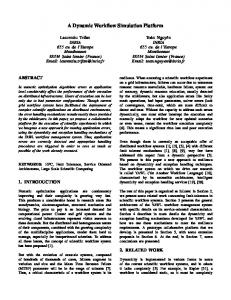
SIMBEANS FRAMEWORK REVIEWED Model building in SimBeans is based on system modeling formalisms (Zeigler et al. 99) as the foundations for state space modeling of simulation systems. Model implementation is based on the JavaBeans component model (Sun 97). In particular, we adopted the JavaBeans event model as an underlying implementation model for realizing discrete event simulation. In a previous paper (Praehofer et al. 99a) we showed how discrete event models can be realized based on the JavaBeans event model. In summary, JavaBeans-based simulation model realization is based on the following concepts (Fig. 1): §a hierarchical composition of model components in turn composed of various types of model elements and submodels §variable objects to store state, input and output values of models §a variable change protocol as an extension of standard property change mechanism to propagate state changes in one component to others §a simulation event protocol to deal with various types of simulationspecific events, like scheduled events, user input events, and state events as discussed in this paper §a continuous equation module for realizing continuous models in block diagram form §a structure event protocol to handle models exhibiting dynamic stucture changes §a central simulator object to run the simulations for the models In the following we review the central modeling, variable structure modeling and simulation event parts (see the earlier paper (Praehofer et al. 99b) for details). In the next section we show the parts for continu-
ous, combined and variable structure modeling and simulation in more sortedEquations 0..n
detail.
«Interface» ContinuousEquation BasicContinuousEquation
+getDomain() : ContVariable [ ] +getTarget() : ContVariable [ ] +isEnabled() : boolean +equation()
continuous equations module
VariableChangeEvent modelElements
«Interface» ModelElement
«Interface» VariableChangeSource
«Interface» VariableChangeListener
listener
0..n
0..n
+variableChange(e : VariableChangeEvent)
Simulator parent +simulate() «Interface» Model
simulator kernel rootModel
BooleanVariable
Variable
-value : boolean
+add(elem : ModelElement) +remove(elem : ModelElement) +connect(from : Variable, to : Variable) +deconnect(from : Variable, to : Variable)
IntVariable
0..n connectedTo ObjectVariable -value : Object
...
BasicModel
variable and variable change module
-value : int
0..1
DoubleVariable
ContVariable derivative
-value : double
model hierarchy module SimEvent «Interface» SimEventSource
0..n
«Interface» SimEventListener
0..n listeners
+processSimEvent(e : SimEvent)
«Interface» TimeEventSource
timeEventList 0..n
«Interface» InputEventSource
inputEventList
ZeroCrossingGuard
0..n
«Interface» StateEventSource
stateEventList Timer
BasicActiveModel
VariableGuard -variable : ContVariable
state event module
-timeOfNextEvent : double
ValueCrossingGuard -value : double
simulation event module
«Interface» StructureEventListener
StuctureEvent «Interface» StructureEventSource
listener 0..n
+modelElementAdded(e : StructureEvent) +modelElementRemoved(e : StuctureEvent) +modelElementEnabled(e : StuctureEvent) +modelElementDisabled(e : StuctureEvent) +connectionAdded(e : StructureEvent) +connectionRemoved(e : StructureEvent)
VariableStructureModel
structure event module
Fig. 1 Class diagram of simulation framework kernel
Model component hierarchy Model components are built up hierarchically from model elements, i.e., variables, event objects and equations and from submodels. The interface ModelElement is a general interface for elements in models. The interface Model extends ModelElement. A model implementation has to implement interface Model. Models have to maintain a list of ModelElements to facilitates the hierarchical structuring of models. In accordance with the JavaBeans standard, model hierarchies are built by adding ModelElements to Models.
Variable and variable change events Variable objects are used for encapsulating values to store state information in models. Depending on the type to store, different specializations (e.g. BooleanVariable, DoubleVariable, ObjectVariable, ...) have to be used.
Variables have the capability to signal value changes. When a Variable is set to a new value, a VariableChangeEvent is signaled. VariableChangeListener objects can register for VariableChangeEvents and are called with the method variableChange with a VariableChangeEvent as the argument. VariableChangeEvents are used to realize state dependencies between models.
Simulation events The simulation framework provides an event mechanism for the implementation of different simulation-specific events. TimeEvents are events that are scheduled in simulation time. InputEvents are events that are triggered by the user in visual interactive simulations. StateEvents are events that are caused by conditions posed on continuous states (discussed in the next section). SimEventSource is the general interface for any component that can trigger simulations events. SimEventListener is the specifica-
tion for listeners to simulation events; listeners are called by their method processSimEvent with a SimEvent object as the argument. A typical implementation of a source for TimeEvents (TimeEventSource) is the Timer. This component allows the setting of a time of next event, which is when it will trigger. Listeners will register for this event and will be called when it occurs. Another TimeEvent component is BasicActiveModel, which is a BasicModel having the capability both to schedule and to react to its own TimeEvents (it implements both TimeEventSource and SimEventListener).
Simulator The simulator is the central object. It maintains important information about the model to allow it to conduct simulations that run efficiently as well as to perform several general functions, e.g., resetting the model state. In particular, it stores a reference to the overall coupled model (rootModel), maintains the event list (timeEventList contains the currently scheduled TimeEventSource components in sequential order), a list of the triggered InputEvent components (inputEventList) to allow execution of user commands, and a list of StateEvent components (stateEventList) to check for state events after each integration step (see Section 3).
CONTINUOUS AND COMBINED SIMULATION The environment for continuous and combined simulation should be seen as an underlying low-level platform for model implementation and simulation. It is intended to serve for a wide variety of simulation problems. Also, it is flexible in the sense that it supports different forms of model implementation. In particular, it supports the following: §realization of reusable simulation components (see (Praehofer 2000)) §translation of model specifications in higher-level formalisms, e.g. non-causal languages, into executable simulation systems (similar to DSBlock (Otter and Elmquist 95)) In the following we illustrate the concepts for model implementation and simulation by first showing continuous simulation, then combined simulation, and finally variable structure system simulation.
Continuous Simulation Continuous system models are described according to the block diagram paradigm (Mathworks 96). However, because of its objectoriented implementation, our system becomes much more flexible than usual block diagram descriptions. For example, it is not restricted to a predefined set of functional blocks; instead, arbitrary functional blocks can be implemented in Java. Furthermore, our system allows structural changes (see the section on variable structure modeling). The specification of continuous behavior is accomplished by defining a network of ContinuousVariable nodes, which then are related in various ways to define the functional dependencies between them (Fig. 2).
o1
i1 derivative equation
o1
d1
output equation
s1
o2
i2 continuous model
i1
o1
... input / output variable ... connect
d1
s1
... derivative / state variable
... domain / target of equation
Fig. 2 Continuous model
... derivative
The class ContVariable, a subclass of the general construct Variable, is used to represent the continuous variables (see Fig. 1, Variable and ContVariable). It has methods to read and write double values. Dependencies between variables are of three different types: §For direct links (connects) one variable defines the value of a connected variable. This is realized by establishing links from the source to the destination Variable (see connectedTo of Variable in Fig. 1). §For derivative relations one variable is defined to represent the derivative for a continuous state variable (derivative of ContVariable in Fig. 1) §For functional dependencies the equations blocks defines the values of some target variables based on the values of some domain variables (see continuous equation module in Fig. 1). The interface ContinuousEquation specifies a general interface for realizing functional equation blocks in the above network. Any object realizing ContinuousEquation must implement the following:
-
a method to get the set of domain variables (getDomain) a method to get the set of target variables (getTarget) a predicate isEnabled to check whether the block is currently enabled or disabled a method equation which defines the code to set the values of the target variables based values of the domain variables
inflow Derivative Equation
derContent
content
Output Equation
level
outflow Tank
Fig. 3 Tank model public class Tank extends BasicModel { double size = 100; ContVariable content = new ContVariable (“content”, Variable.VARIABLE, this) ContVariable inflow = new ContVariable (“inflow”, Variable.INPUT, this); ContVariable outflow = new ContVariable (“outflow”, Variable.INPUT, this); ContVariable derContent = new ContVariable (“derContent”, Variable.VARIABLE, this); ContVariable level = new ContVariable (“level ”, Variable.OUTPUT, this); public Tank () { content.setDerivative(derContent); this.add (new DervativeEquation ()); this.add (new OutputEquation()); } // inner class for derivative equation public class DervativeEquation extends BasicContinuousEquation { public Variable[] getDomain () { return new Variable[] {inflow, outflow}; } public Variable[] getTarget () { return new Variable[] {derContent}; } public void equation () { derContent.setValue (inflow.getValue() - outflow.getValue());} } // inner class for output equation public class OutputEquation extends BasicContinuousEquation { public Variable[] getDomain () { return new Variable[] {content }; } public Variable[] getTarget () { return new Variable[] {level}; } public void equation () { level.setValue (content.getValue() / size; } } } Program 1 Continuous model of tank system
Fig. 3 shows the block diagram of a tank model as an example of a continuous model. Program 1 shows the implementation of this model as a direct translation of the block diagram into Java code. Variables are implemented via several ContVariable objects. The equations are defined in two inner classes derived from BasicContinuousEquation. In the constructor the derivative relation is declared between content and derContent and the two equations are instantiated and added as components. Coupled continuous models are built connecting input and output variables of components. In Fig. 1 a model of a two-tank system is shown where the outflow of one tank is equal to the inflow of the other. The flow between the two tanks is computed by a flow equation based on the difference of levels of the two tanks.
level in in flow flow
out flow
tank1
flow equation
flow
level in flow
out out flow flow tank2
two-tank model
Fig. 1 Coupled continuous model Program 2 then shows the implementation with the flow computed by an inner ContinuousEquation class FlowEquation. In the constructor the structure of the model is built by first adding the components to the coupled models and then defining the connections between variables. public class TwoTank extends BasicModel { double capacity = 1; ContVariable flow = new ContVariable (“flow”, Variable.VARIABLE, this); ContVariable inflow = new ContVariable (“inflow”, Variable. INPUT, this); ContVariable outflow = new ContVariable (“outflow”, Variable. OUTPUT, this); Tank tank1 = new Tank (); Tank tank2 = new Tank (); FlowEquation flowEqu = new FlowEquation(); public TwoTank () { this.add(tank1); this.add(tank2); this.add(flowEqu); connect(inflow, tank1.inflow); connect(outflow, tank2.outflow); connect(flow, tank1.outflow); connect(flow, tank2.inflow); } // inner class for flow equation public class FlowEquation extends BasicContinuousEquation { public Variable[] getDomain () { return new Variable[] {tank1.level, tank2.level}; } public Variable[] getTarget () { return new Variable[] {flow}; } public void equation () { flow.setValue ((tank1.level.getValue()–tank2.level.getValue()) * capacity); } } } Program 2 Continuous model implementation of a two-tank system Continuous simulation is accomplished using standard numerical integration methods and employing the continuous model definition as outlined above. A main task in continuous simulation is to guarantee the right sequence of execution of the ContinuousEquation objects. For a continuous equation to be evaluated, all its domain variables must be known. Sorting in a particular continuous equation means that its target variables are known henceforth. The right sequence then can be determined by starting with the state variables and the constants whose
values are known beforehand and sorting in the continuous equations so that the above requirement is fulfilled. The Simulator object maintains a list of sorted equations (sortedEquations in Fig. 1) to compute the derivatives of state variables for numeric integration.
Combined Simulation Combined discrete/continuous modeling and simulation deals with the integration of continuous and discrete event model elements. On the one side, continuous changes of continuous state may cause state events to occur. Whenever a continuous variable reaches a certain threshold, an event occurs. On the other side, events will change continuous states and alter continuous model behavior. State events are realized by a specialization of the general SimEvent protocol (Fig. 1, state event module). Any component implementing StateEventSource may trigger state events. StateEventSources are implemented in various ways. Fig. 1 also shows a basic state event hierarchy. VariableGuard is a basic class to observe a continuous variable. It has two subclasses, ZeroCrossingGuard and ValueCrossingGuard, which signal a state event whenever the observed variable exceeds zero or a particular threshold, respectively. A multi-model (Zeigler et al 99) is a model which subsumes several different models. In a multi-model, depending on the current state the process is in, one of the set of model behaviors will apply and will describe the process appropriately. The transitions from one state to the next state with a different applicable model signifies a qualitative change in the dynamic behavior. We call such qualitative states phases and qualitative changes in behavior phase transitions. public class Tank extends BasicModel implements SimEventListener { ... final int EMPTY = 0, NORMAL = 1; FULL = 3; ValueCrossingGuard fullGuard = new ValueCrossingGuard (content, 100.0); ValueCrossingGuard emtpyGuard = new ValueCrossingGuard (content, 0.1); IntVariable phase = new IntVariable(“phase”, this, EMPTY); public Tank () { ... fullGuard.addStateEventListener (this); emptyGuard.addStateEventListener (this); } public void processSimEvent (SimEvent e) { if (e.getSource() == emtpyGuard) { if (phase.getValue() == EMPTY) { phase.setValue(NORMAL); } else if (phase.getValue() == NORMAL) { phase.setValue(EMPTY); } } else if (e.getSource() == fullGuard) { if (phase.getValue() == NORMAL) { phase.setValue(FULL); } else if (phase.getValue() == FULL) { phase.setValue(NORMAL); }} } // inner class for derivative equation with phases public class DervativeEquation implements ContinuousEquation { public void equation () { double diff = inflow.getValue()– outflow.getValue(); if (phase.getValue() == FULL) { if (diff > 0.0) derContent.setValue (0.0); else derContent.setValue (diff); } else if (phase.getValue() == NORMAL) { ... } Program 3 Tank multi-model Program 3 shows an extension of the tank model where different phases are distinguished, viz. EMPTY, FULL and NORMAL, where the behaviors differ. The phase transitions are triggered by two ValueCrossingGuards and handled in the processSimEvent method.
Variable Structure System Simulation A variable structure system (Zeigler and Praehofer 90, Uhrmacher and Zeigler 96) is a model that shows structural changes during a simulation run. Variable structure models require a protocol for handling structural events. A variable structure model must provide methods for adding/removing and enabling/disabling of model elements and for adding/removing connections. On the other side, an event protocol is used for signaling structural changes. A variable structure model is responsible for signaling any changes in its structure to allow interested components to react. Fig. 1 shows the structure event protocol. StructureEventSource is the interface that must be implemented by any variable structure model. A component listening to a structure event will implement StructureEventListener. StructureEvent with its subclasses carries the information about the event. VariableStructureModel, derived from BasicModel, is a basic implementation of a model with structure changes and therefore implements StructureEventSource. The Simulator is a component that must be notified of any structural change and therefore implements StructureEventListener. It must be informed of any structural changes and will update its internal structures, e.g., the current list of continuous equations, according to the structure event notifications. A simple example of a variable structure model is an extension of the two-tank system which allows connecting and disconnecting the two tanks (Program 4). When the two tanks should be connected, the flow variable is set to be of type VARIABLE, which means that the value must be defined by some equation, and the flow equation is enabled. When the two tanks are disconnected, we set the flow to be of type CONSTANT with value 0.0 and disable the flow equation. public class TwoTank extends BasicModel { ... public void disconnectTanks () { flow.setConstant(0); flowEqu.disable(); } public void connectTanks () { flow.setVariable(); flowEqu.enable(); } } Program 4 Connect and disconnect two tanks An earlier paper (Praehofer 2000) discusses a more advanced example of a variable structure model where particles moving in space are coupled dynamically through force couplings based on vicinity detection.
PAPER MILL TRAINING SIMULATORS The continuous simulation system and the modeling principles described (Praehofer 2000) are used in an ongoing project to realize training simulators for paper mill plants. Training simulators are common in the paper mill domain to train operators in supervising and controlling plants because training on the real plant is too dangerous and costly. In former projects, training simulators have been built with standard simulation tools. In using the Java-based simulation environment, we aim to achieve a new level of quality in training simulators. The course topics are presented to the student in an interactive way and with multimedia presentations. In particular, after being presented the necessary theoretical background for a topic, e.g., PID controllers, the student can start an interactive simulation applet where the student can directly influence the systems, set parameters, define control strategies, and immediately observe the results. In this way the student is introduced step by step to the problems of controlling a paper plant, starting with simple control loops, getting familiar with the main parts of a plant, to finally controlling the entire plant. The process in a paper machine – which is the subject of our current project – starts with a mixture of water and cellulose, then proceeds by laying the liquid pulp on a belt, rolling it, and successively extracting water from it until it is solid and dry. Components to model such a system have to deal with the mixture of water and cellulose (called
pulp), storing pulp in tanks, transporting pulp in pipes and with pumps, handling lengths of paper with different consistency, and drying and rolling of lengths. The physical circumstances in this process are extremely complex and are often not tractable to a mathematical model. On the other side, the requirements on precision for training purposes is not too high. (It suffices for the behavior of the real system to be reproduced in such a way that a human expert classifies the behaviors to be compatible.) The approach that we take is to use characteristic curves gained from realworld measurements to infer functional dependencies between variables. In the previous paper (Praehofer 2000) we presented general guidelines for building reusable simulation components. As one important issue, the separation of flow and effort components similar to Bondgraph modeling was identified. While effort components should be seen to provide effort states and are influenced by flows, flow components realize the flows between components, these flows depend on the effort states of the connected components. With these modeling guidelines for building reusable simulation in mind, a library of reusable components was created that allows us to compose a wide range of paper mill and related systems. The components range from basic pulp tanks, pipes, pumps, rolls and elementary control components. Also we have prefabricated the usual GUI components for visualizing process states and for user inputs. In the following we outline the component library.
Paper mill component library Elementary for modeling paper production is the representation of pulp, which is basically a mixture of water and fiber. It is realized by a structure Pulp with two variables, total and fiber, representing the total amount of pulp and the amount of fiber contained (Fig. 4 (a)). This structure is used to model effort states as well as flow rates. A typical effort component, e.g., a tank for pulp, has interfaces for inflow and outflow of pulp. The PulpOutlet interface (Fig. 4 (a)) has an output variable available of type Pulp which provides information about what kind of and how much pulp the component can deliver currently at this outlet. In this sense it provides information about the internal state of the component and therefore is an effort variable. And it has one input variable outflow where the actual amount of flow through the outlet is deterimined. The PulpInlet interface (Fig. 4 (d)) has one real output variable acceptable which provides information about how much pulp the component can take at this inlet. In this sense it provides information about the internal state of the component and therefore is an effort variable. This interface also has an input variable inflow of type Pulp where the amount of input of Pulp is given. For control purposes, a tank may output additional information representing sensor measurements. In our components, a tank outputs its fill level and a consistency value representing the percentage of fiber in the pulp. controller
level
rate
available
total fiber
pulpOutflow
acceptable
available
pulpFlow
acceptable
pulpInflow
Pulp PulpOutlet (a) Pulp
(b) PulpOutlet interface
flow model (c) Flow component
PulpInlet (d) PulpInlet interface
Fig. 4 Paper mill components Flow components are any components transporting pulp (Fig. 4 (c)). They connect PulpOutlet and PulpInlet interfaces by reading the acceptable and available states of the connected components and determining the pulpFlow. Flow components range from simple pipes with a certain capacity, to valves and pumps which usually are
controlled, to transport delays with changes in the pulp consistency for modeling paper rolls and dryers. For control purposes, PID control components and on/off control components are available currently. They can be set interactively. Finally there is a set of visualization and animation components and components for user input. Fig. 5 shows a simulation system of the first part of the paper mill plant where the initial pulp mixture is produced.
Fig. 5 Paper mill simulation applet
SUMMARY Although the system outlined above may appear to be complex and difficult to handle compared to existing block-oriented simulation systems, we argue that it has many advantages that justify the approach taken. The environment is efficient. For simulation execution we rely on HotSpot technology (Sun 99), which does compilation and optimization of byte-code dynamically based on run-time performance measures. Our environment is constructed so that elementary, frequently called methods are written in a way that HotSpot can inline them and produce efficient code. The environment is flexible. The environment relies on interface definitions for model elements, e.g., ContinuousEquation or StateEventSource, which leave the implementations open. This makes model realization extremely flexible, extensible and customizable to application-specific demands. The environment is powerful. The support of models with structural changes brings great modeling power to our environment not present in many conventional continuous simulation systems and languages. It allows creation and deletion of model components, adding, removing, or changing of couplings, changes in the model definitions, etc. This supports the realization of advanced modeling concepts, as needed for multi-agent system simulation, but also can improve simulation performance. The environment supports reusability. The previous plaper (Praehofer 2000) presents general guidelines for how reusable components should be built. The implementation concepts discussed in this article support the application of these guidelines. Our model implementation concepts are compliant with the JavaBeans component model, allowing us to manipulate our simulation components with standard bean builder tools.
REFERENCES Cellier, F.E.. Continuous System Modeling. 1991. Springer-Verlag, New York.
Mathworks, Inc. 1996. SIMULINK, User’s Guide. Prentice Hall, Englewood Cliffs, NJ. Otter M.; Elmquist H.. 1995. “The DSblock model interface for exchanging model components”. In Proceedings of the 1995 EUROSIM Conference (Vienna, Austria, Sept. 11.-15.). Elsevier Science Publishers, 505-510. Praehofer, H.; A. Stritzinger; J. Sametinger. 1998. “Using JavaBeans to teach Simulation and using Simulation to teach JavaBeans”, 12th European Simulation Multiconference (Manchester, UK, June 16-19). SCS Press, San Diego, CA., 886-890. Praehofer, H.; A. Stritzinger; J. Sametinger. 1999a. “Discrete Event Simulation using the JavaBeans Component Model”. In Proceedings of the International Conference on Web-Based Simulation (San Franzisco, CA, Jan). SCS Press, San Diego, CA, 107-112. Praehofer, H.; A. Stritzinger; J. Sametinger. 1999b. “Concepts and Architecture of Simulation Framework Based on the JavaBeans Component Model”. Journal of Future Generation Computing Systems, Special Issue on Web-Bsed simulation, 1999. Praehofer, H. “Building Reusable Simulation Components”. In Proceedings of the International Conference on Web-Based Simulation 2000 (SanDiego, CA, Jan 2000) (this volume). Sun Microsystems. 1997. JavaBeans 1.01 API Specification. Sun Microsystems, Inc. (see http://java.sun.com/Beans/spec.html). Sun Microsystems. 1999. The Java HotSpot Performance Engine Architecture, A White Paper About Sun's Second Generation Performance Technology. Sun Microsystems, Inc. (see http://java.sun.com/products/hotspot/whitepaper.html) Uhrmacher, A.M.; B.P. Zeigler. 1996. “Variable Structure Models in Object-Oriented Simulation”. Int. J. Gen. Systems 24, no. 4: 359-375. Zeigler, B.P.; H. Praehofer. 1990. “Sytems Theory Challanges in the Simulation of Variable Structure Systems”. In Proceedings of EUROCAST ’89. Springer-Verlag, LNCS 410, Berlin, 41-50. Zeigler, B.P., H. Praehofer, and T.G. Kim. 1999. Theory of Modeling and Simulation, 2nd Edition. Academic Press, London.
BIOGRAPHY Herbert Praehofer is assistant professor at the Johannes KeplerUniversity in Linz, Austria. His research interests include modeling and computer simulation, modeling theory, object oriented modeling and design, and systems engineering. He received a Ph.D. in computer science from the Johannes Kepler University in 1991. In 1989 he was visiting scholar at the Department of Electrical and Computer Engineering of the University of Arizona, Tucson, Arizona. He is co-author of the forthcoming book “Theory of Modeling and Simulation” to be published by Academic Press. Alice Schoeppl is a research assistant at the Johannes Kepler University in Linz, Austria. She received a Master degree in computer science from the Johannes Kepler University in 1999. Her research interests include modeling and computer simulation and object oriented and componentbased software engineering.