22, No. 2, June 2006. 235. DESIGN AND SIMULATION OF CONTINUOUS DIELECTROPHORETIC ... flow rate as the time duration while the flow passed the electrical fields, and ... upon a particle in the presence of a non-uniform electric ... symbol ydeflection denotes the transverse deflection dis- ... section, as shown in Fig.
DESIGN AND SIMULATION OF CONTINUOUS DIELECTROPHORETIC FLOW SORTERS T.-S. Leu *
H.-Y. Chen **
F-B. Hsiao ***
Department of Aeronautics and Astronautics National Cheng Kung University Tainan, Taiwan 70101, R.O.C. ABSTRACT This paper was an attempt to investigate, through numerical simulation, the designs of DEP flow sorters when applied with different ratios of the electrodes to generate different electrical fields, and to explore the sorting capability of the flow sorters, defined as the degree of particle deflection, under different operation of parameters. In order to obtain the maximal DEP negative particle deflection, which was believed as an indicator of greater sorting capability, we have investigated different non-uniform electrical fields produced by combinations of electrodes with different length of two poles, ranging from 1:2 up to 1:9. The finding of numerical simulation indicated that the length ratio 1:3 of the electrode poles produced the electrical fields that maximized the particle deflection. Moreover, different parameters of applied voltage, flow rate, particle diameters, and distance between two electrical poles were designed to investigate their effects on particle deflection of flow sorters. The numerical simulation of the study showed that the DEP flow sorter was demonstrated as a linear system with respect to the applied voltage and particle diameter. In this study, we tried to operationally define flow rate as the time duration while the flow passed the electrical fields, and thus investigated how particle deflect with the different time given. We found that the particle deflected more when the flow was allowed with longer time to pass the electrical fields. The study also showed that the distance the particles deflect from the centerline is in inverse proportion to the square distance between the two electrical poles. Keywords : Dielectrophoretic, Sorters.
1.
INTRODUCTION
Sorting cells of interest from mixtures of various kinds of cells for cellomics studies is often required in many researches and medical diagnostic applications. It has been widely acknowledged that the effective sorting in many micro-fluidic and Lab-On-A-Chip devices provided many advantages over the conventional fluorescent activated cell sorting (FACS)[1], such as low consumption of samples without sacrificing sensitivity, closed system reducing the potential biohazard risks and preventing cross-contamination, and feasibility of making portable and disposable devices [2]. Over the years, the scientists have developed many particle and cell handling microfluidic devices. For example, there are micro-fabricated fluorescence-activated cell sorting (µFACS)[3,4], magnetic-activated cell separation (µMACS)[4], automated single-cell sorting using dual-beam optical trapping [5], optoelectronic tweezers for particle manipulation [6], and micro-fabricated flow switch for sample injection and * Assistant Professor
** Ph.D. candidate
cell/particle sorting [7,8]. Micro-fabricated flow switch devices employ the laminar behavior in micro flow channels. These devices have two-dimensional structures with two sheath buffer inlets and one sample inlet located in the middle [7]. The sample flow is controlled by the flow ratio of the right and left buffers. A multi-outlet flow switch was also demonstrated by the similar principle [8]. Air-liquid two-phase [9] and three-dimensional sheath flow type [10] micro-channels were also reported. These types of flow switches require the control of sheath flows realized by abruptly changing pumping pressure, however, fast and precise control can be difficult sometimes. A cell sorter using laminar sheath flow and electrostatic force was reported [11,12]. In this paper, an on-chip sorting for particle handling using dielectrophoresis (DEP) is studied. The DEP sorting approach is particularly suitable for operating at the micrometer scale and allows the analyzing and discrimination of cells of interest. Due to differences in their complex dielectric properties and dimensions, DEP forces of different magnitudes acting on the cells can be
*** Professor
Journal of Mechanics, Vol. 22, No. 2, June 2006
235
obtained, thus deflected are the cells of interest along a pre-determined trajectory. This technique is also labelfree, i.e., an unique advantage that cells are unaltered during the measurement process. The instrument can easily discriminate sub-micrometer size differences in calibrated polystyrene particle diameters. Since there is no mechanical structures moved by an actuator, the flow in the DEP flow sorter is smooth and, meanwhile, without dead spaces. These features obtained in the design of this paper are, in fact, required by many micro-fluidic systems.
2.
DESIGN OF CONTINUOUS DEP FLOW SORTER
Dielectrophoresis (DEP) refers to the forces induced upon a particle in the presence of a non-uniform electric field. A particle within an electric field forms an induced dipole, which will experience a force due to the field gradient [13]. The analytical expression of DEP force is given by [14]: G 1 Fdep = πa 3 ε m ε 0 Re [ K * (ω)] ∇( E 2 ) 4 K * (ω) =
(1)
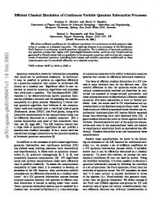
Schematic diagram of the DEP flow sorter
sheath flows. The focused particles enter the sorting channel section along the centerline of the flow sorter. A pair of electrodes with different aspect ratios were designed in the sorting channel section, which generates a non-uniform electric field. Particles (cells) within sorting channel section induce the DEP forces to deflect themselves transversely from the centerline. The symbol ydeflection denotes the transverse deflection distance of a particle (cell) at the exit of sorting channel section, as shown in Fig. 1. As the particles (cells) go out the sorting channel section, they go into the collecting channel section. A divergent channel with multioutlet was designed in the collecting channel section to magnify the particle deflection distance.
ε*p − ε*m
3.
ε*p + 2ε*m
ε*p = ε p − j
σp ω
; ε*m = ε m − j
σm ω
(2)
where E is the field strength, a is the particle diameter, εm and εp are the permittivities of the surrounding medium and the particle respectively, ε0 is the vacuum permittivity, σm and σp are the conductivities of the surrounding medium and the particle respectively, and ω is the angular frequency of the applied electric field. The direction of the induced dielectrophoretic force depends upon the sign of the term Re [K*(ω)]. It can presume any value between 1 to –1/2, depending on the operating frequency of the electric field and permittivity and conductivity of the particle and the surrounding medium. If Re [K*(ω)] > 0, it is called positive DEP. The positive DEP forces result in particle attraction to the maximum of electric field gradient. In contrast, the negative DEP (Re [K*(ω)] < 0) causes particles to be repelled from the maximum of electric field gradient. Figure 1 shows the schematic diagram of the DEP flow sorter. The unique features of DEP flow sorter can be divided into three sections from upstream to downstream: (i) hydrodynamic focusing section; (ii) sorting channel section; and (iii) collecting channel section. Hydrodynamic focusing section utilizes laminar flow behavior in micro channels. This section has two-dimensional structure with two sheath flows and one sample flow located in the middle. The sample fluid was constricted into a single particle stream by adjusting the velocity ratio between the sample and the 236
Fig. 1
SIMULATION
In this study, numerical simulation was performed with the CFD-ACE + software (CFD Research Corporation, Huntsville Alabama), a multi-physics package. The mesh-independent test runs were made within the range between 4428 and 11154 cells. Although operated in the laminar flow regime, a rather fine mesh was needed to account for the detailed features of the sorting mechanism. The mechanisms of hydrodynamic focusing and DEP sorting of particles (cells) were included in the numerical simulation. Calibrated polystyrene particles are used in simulation to validate the system. Various parameters including electrode aspect ratios, applying voltages, and average flow velocities are studied to investigate their relationships with system sensitivity. The properties of the polystyrene particle and surrounding medium are listed in Table 1. The trajectory of the particle positions within the inhomogeneous electric field of the sorting channel section is of particular interest. The transverse deflection distance ydeflection at the exit of sorting channel section will be used to characterize the performance of the DEP flow sorters.
4.
RESULTS AND DISCUSSION
As a particle moves within the DEP flow sorter, it deflected laterally in y direction. There exist two G forces acting on it. One is the DEP force Fdep , shown Journal of Mechanics, Vol. 22, No. 2, June 2006
Table 1
Medium and particle properties at 1Mhz AC signal medium
Density ρ (kgm−3) Viscosity µ (kgm−1sec−1) Conductivity σ (Sm−1) Permittivity ε (Fm−1)
Polystyrene (latex) particle
1000
1100
0.000892 3
0.009
80 × 8.854e−12
2.5 × 8.854e−12
in Eq. (1), the other is so called Stokes’ drag FD. The y-coordinate of particle, as well as its relative velocity to the fluid in y-direction v, can be expressed by the following equation.
mp
d2y dv = mp = [ Fdep ] y − [ FD ] y dt dt 2
(3)
where mp is the mass of the particle, [Fdep]y and [FD]y are DEP force and Stokes’ drag in y-direction respectively. For the limits of low Reynolds numbers, the analytical expression of Stokes’ drag in y-direction is given by the Stokes’ formula [15] [ FD ] y = 3πaµv
(4)
where a is the diameter of the sphere particle, µ is the viscosity of fluid and v the velocity of particle in y-direction. By substituting Eq. (4) into Eq. (3), one can rewrite Eq. (3) m p dv [ Fdep ] y dv + v = τv +v = 3πaµ dt dt 3πaµ
(5)
where τv is the momentum response time of particles. One important parameter, called the stoke number, in fluid-particle flows is defined as Stv =
τv τv U ave = τF L
(6)
where τF the characteristic time scale of the flow filed. For example, the characteristic time for the flow through the micro sorter may be L/Uave where L is the length of the sorting section channel and Uave is the inlet flow velocity. One can find Stv = 10−6 ~ 10−5