Every polygon in the 3D folded structure has a corresponding face in the 2D polygons. The shape .... weight wood-pulp paneling materials with folded cores.
A Continuous Folding Process for Sheet Materials E. A. Elsayed and Basily B. Basily Department of Industrial and Systems Engineering Rutgers University 96 Frelinghuysen Road Piscataway, NJ 08854-8018 ABSTRACT In this paper, we present a new and innovative sheet material folding technology and the associated advances in folding different patterns using continuous manufacturing techniques. A novel approach is developed for the continuous folding process where sheet material is progressively folded in two dimensions, through a set of rollers, followed by a configured roller for the final folding in the third dimension. The final roller can be designed for longitudinal folding, cross-folding and angular folding to produce the desired folded pattern. This process is more economical than traditional forming processes. An application of this process to the production of impact energy absorption structure is presented. Keywords: folding technology; rollers; Kraft paper; folded sheet; energy absorption; Chevron pattern structures; lamination; tessellations.
1.
INTRODUCTION
A novel technique for continuous sheet material folding is developed in which the sheet material is progressively folded in the two dimensions normal to feeding direction through a set of rollers, followed by a configured roller for the final folding in the third dimension, the two dimensional pre-folded sheet transforms into the final three dimensional folded shape, as it passes through the configured main roller.
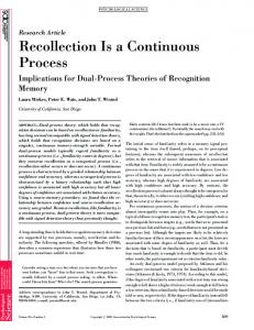
Figure 1. Folded Chevron Pattern From a Flat Sheet Figure 1 shows what we refer to as a Chevron pattern, made of paper, which is generated through a sequence of folding steps. This pattern can also be produced by folding different sheet materials, such as aluminum, copper, stainless steel, Kraft paper, composites and plastics. It should be emphasized that folding technology for sheet material, is one of the most efficient shape and structural forming processes. Other production methods such as stretch-drawing, forging, pressing and fabrication [1] may produce costly three-dimensional patterns that appear similar, but the mechanical properties of the resultant patterns are significantly different. This is particularly so in the case of folding thin sheet materials where variations in sheet thickness and/or mechanical properties are unacceptable.
1
Additionally the developed continuous sheet folding technique is capable of producing very intricate structures that can be economically produced at high-speed from rolled stock through the use of single manufacturing process; namely folding.
2.
BASIC SHEET FOLDING CONCEPT/THEORY
Given a pair of points on a surface, measurement of the length of the shortest path that can be drawn on that surface connecting them is called the intrinsic geometry of the two points [2, 3]. Folding preserves the intrinsic geometry, since any curve drawn on a sheet will have the same length before and after folding. This holds as long as the sheet thickness is relatively small. Of course, thicker sheets will experience deformation and stretching when the bending is significant. In this paper, we consider the former case only, i.e., no extensions in the sheet. Theoretically such surfaces are not stretched in any direction and hence, folded structure can be readily unfolded back to flat surfaces without any variation in sheet thickness or dimensions. One of the important properties of folded structures, also referred to as developables by Duncan and Duncan [4], is that the tangent plane at a point makes contact with the surface along the entire length of a straight line in the surface. This line is called a generator of the surface. An element of folded structure is constructed by having the generators of two surfaces coincide. Thus the two surfaces will only meet at one line. In folding a flat sheet of material into a three-dimensional folded structure, it is important to ensure the following conditions in order to guarantee that the sheet can indeed be folded in the specified pattern: 1.
Tessellations (normally polygons) made of identical polygons as shown in Figure3 are considered a set of 2D polygons lying on a common plane (the flat sheet). These polygons must be convex. Every polygon in the 3D folded structure has a corresponding face in the 2D polygons. The shape of each face is the parallel projection of the corresponding polygon onto a plane a plane perpendicular to that polygon. No face may overlap with any other, Bangay (5).
2.
Each vertex in a folded structure must have the angles meeting there from the adjacent faces totaling 2p as a limiting condition for the vertex to unfold flat [6, 7].
Therefore, not any set of 2D polygons on a flat sheet is foldable. Indeed, Bern and Hayes [2] show that it is NP-hard to determine whether a crease pattern (2D polygons) is flat foldable. Hull [8] and Kawasaki [9] focus on necessary and sufficient conditions on overlap orders, resulting in a characterization of flat foldability for general crease patterns. Lang [10] describes an algorithm to construct “uniaxial” bases, which can be folded into arbitrarily complex models. Folded patterns also have one or more elementary flat surface, each of which has a specific geometrical shape which forms the basic building elements of the folded pattern. Additionally, a combination or multiplication of these elementary flat surfaces of a specific geometrical shape constitutes the basic building cell of a folded pattern, as it is repeated in two dimensions, creating the three-dimensional folded shape. In the case of Chevron folded pattern, as an example, the basic building element is a flat surface polyhedron defined by its length a, width b, and the included angle f , shown in Figure 2 where both a and b are of o
arbitrary lengths with typical included angle f =60 , however f could theoretically assume any value in the range of 0 £ f £ p / 2 .
2
The basic building cell of the Chevron pattern consists of four identical polyhedron [A, B, C, and D] each of length a, width b and an included angle f = 60o . The cell is arranged laying flat prior to folding as shown in Figure. 3. Also the repetition of the cell ‘m’ times in the direction of the arrow along the X axis provides the unfolded length of the tessellated sheet, while the cell repetition ‘n’ times in the direction of the arrow along the Y axis provides the unfolded width of the tessellated sheet.
Figure 2. Basic Element Of The Chevron Pattern Creation of three dimensional folded Chevron structures from a sheet tessellated with the basic building cell is achieved by inducing a permenant edge bending in particular directions between these four polyhedron elements and along all the edges of these four basic elements. This generates the basic building block which is a three dimensional structure with block length Lq , block width Wq and block heigh hq , the building block of the Chevron pattern is shown in Figure 4. Reptition of the building block in the X and Y directions forms the entire folded Chevron structure shown in Figure5.
Figure 3. Basic Building Cell of Tessellated Chevron Pattern Sheet
3
A
Figure 4. Basic Building Block of Tessellated Chevron Pattern Sheet
Figure 5. Three Dimensional Chevron Structure
During any folding stage, the geometrical dimensions and angles of the folded structure can be determined in terms of the three parameters of the basic building cell. For example, consider a Chevron pattern with the following parametes (refer to Figure 6): a b f
basic element length basic element width basic element angle
For an inclined angle q (also called folding angle) with respect to X-Y plane, where q varies from 0 corresponding to flat unfolded cell to q = p / 2 , corresponding to fully folded block, The geometrical parameters of the basic folded block, corresponding to that inclined angle q , which refers to a given state of folding are given by c = a sin f h = a sin f sin q g = b sin f g = sin -1 (sin f sin q )
a = sin -1 (tan g / tan f ) y = tan -1 (
1 ) tan f cosq
4
u = b cosy
v = a cos g
Figure 6. Geometrical Parameters of the Basic Building Block of Chevron Pattern For a folded Chevron pattern with m tessellations of the basic building element of its flat surface polyhedron in the X direction and n tessellations in the Y direction of same basic building element of flat surface polyhedron, the unfolded sheet of thickness t would have an initial length, width, and thickness volume given by Lo = m a Wo = nb cos f Vo = m nt a b cos f When the above tessellated sheet is folded to an inclined angle q , the corresponding fold dimensions (length, width, thickness and volume) are given by Lq = m a cos g Wq = n b cosy hq = a sin f sin q + t Vq Lq .Wq hq = m n a 2 b sin f sin q cos g cosy
Where Lq , Wq , hq and Vq are the fold length, width, height and volume respectively. Since the structure is initially folded from a flat sheet of material with length Lo , width Wo , sheet thickness t and material density z , therefore the fold apparent density is determined as
zq =
z Vo Vq
The relative density ratio is then given by:
5
z a = [1/((cos g cos y ) (( sin f sin q ) + 1))] t zq
which indicates that the apparent density of the folded structure varies with the folding angle q with the fold apparent densities equal to the unfolded sheet at q = 0 and q = p / 2 . This also indicates that there is a fold minimum apparent density at about q = 45o as shown in Figure 7 for a constant a/t ratio. Fo ld co rrela ted ang ula r pa ram e ters
90 ga m m a ps i alpha V olu m e rat io
80 70 60 50 40 30 20 10 0
0
10
20
30
40
50
60
70
80
90
F o ld Inclina tio n a ng le (T he ta )
Figure 7. Variation of Fold Geometry a , g , and y and Density Ratio With Folding angle q
3.
ADVANTAGES OF SHEET FOLDED STRUCTURES AND APPLICATIONS
The folded sheet configuration may be adapted by changing scale, parameters of the element geometry and material composition to suit a given application with specific mechanical properties, such as compressive and shear strength and impact energy absorbing capacity. Typical applications in packaging may include Kraft paper cores for laminated panels that would outperform corrugated cardboard or multi-layer folded blocks that could replace Styrofoam in space filling and shock absorbing applications. Folded patterns may also be used as decorative packages such as trays and boxes for displaying cosmetics and similar products. In the aerospace industry, light-weightcores folded from aluminum and composites could improve the performance of such cores and expand its use in airframes, fuselage, floors, wings, and tails. Additionally folded structures can be generated with customized stress/strain characteristics in predetermined values/directions designed to fit surfaces with any curvature. In civil engineering infrastructures, Applications could include aluminum and steel laminated folded structures as panels for warehouse roofs. Interior walls made from particle wood could be replaced by lightweight wood-pulp paneling materials with folded cores. Likewise, stainless steel decorative folded designs for building facades, interiors of elevators and floor decks can be made of folded patterns with prespecified geometries and properties. Heavier gauges of high-strength steel sheets can be folded for applications in buildings and steel structures, bridges, and replacements of concrete decks. In the transportation industry, aluminum and steel laminated panels may be used in light-weight sturdy trailer beds, automobile body structures to provide frames of higher strength, rigidity, and vibration dampening. The light-weight/high-strength ratio and high impact energy absorbing properties make folded structures most suited for bumpers, hoods, crash protecting car doors and highways crash barriers.
6
Other applications include construction of filters and heat exchangers. This can be also designed from folds with specific shape flow channels, which would provide controlled flow rate and large surface area. The use of silicon carbide/ceramics, fabricated from UV photo-curable pre-ceramic polymers of SiC and Si3N4/SiC, with higher than 85% ceramic yield in foldable paper form, and optimizing the fold geometry, would produce a uniquely folded ceramic particulate filter with high tortuosity [6], strength and temperature oxidation resistance. UV cross-linkable pre-ceramic polymers can also be used to fabricate uniquely folded ceramic, carbon and polymer PEM fuel cells. In military applications, Kraft paper folded pads, designed for impact energy absorption out performed current structures used in high-velocity air drop. This is due to the unique energy absorbing capability of the folded structures in three dimensions, compared to the unilateral energy absorbing ability of other commercially available cushioning pads. The design of these energy-absorbing pads can be tailored to provide predetermined load deceleration, and impact energy absorbing capacity compatible to the fragility of the package content. Folded patterns from sheet materials exhibit superior crush resistance and energy absorption characteristics. Since the technology applies to paper, plastic, sheet metal, composites, cloths and other foldable sheet materials, the commercial applications for this technology are numerous. 4.
SHEET FOLDING PROCESS
The folding process uses minimal energy in forming since the material does not entirely stretch or undergoes large scale yielding conditions to acquire the final shape. The work is done in a localized scale in the form of plastic bending of the edges of the facets only. Therefore, extremely lower forces and energies are required in the folding process when compared with typical metal forming process such as pressing, stamping or stretch forming [7]. The plastic bending force and energy required to permanently fold these elements to produce a given pattern is derived from the plastic work involved in the bending these flat elements around the element edges to a given permanent angle that corresponded to initial folding angle of the sheet, hence, for bending a sheet of thickness t to a radius of curvature r the strain at a distance y from the neutral plane is given by (see Figure 8):
Figure 8. Variation of Folded Angle With Bending y 1 where is the curvature of the elastic curve of the deflected sheet., the bending moment at this r r cross section of the sheet is given by:
e=
7
M = ò s y l dy
Assuming elastic-perfectly plastic sheet material, then the bending moment, M on an element edge of a length l is given by: M =l
+t / 2
ò
-t / 2
where e y =
yy
t/2
0
yy
s y dy = ò s y dy +
ò y dy
yy
is limiting elastic strain r Since the stress in the elastic portion of the bent cross sections is given by Ey s = , where E is the material Young’s modulus, then, r t2 2 E M = l y 3y + l s y ( 4 - y 2y ) 3 r 4 s yr since y y = then E
l t2 1 3 r2 M= s y - ls y 2 4 3 E
and the bend curvature is given by 1 ls y 3 E2
3
1 = r
1 2 lt sy -M 4
When the moment M is removed after plastic yielding of bent edge, the material will spring back, decreasing the initial bent angle and the resulting final curvature that the bent edge retains is given by: 1 ls y 3 E2
3
1 = rres
1 2 lt sy -M 4
-
12M Et 3 l
This spring back is due to the residual stresses in the plastically bent edge resulted from the elastic strains being locked in position by yielding of the external layers along the cross section of the sheet material. The distribution of these residual stresses is shown in Figure 9 with maximum values of: 6M ' s res = s y - 2 at the outer surface of the cross section, and lt 12M y y " s res =sy at the height of y y from the cross section neutral axis. l t3
8
Figure 9. Distribution of Residual Stresses in a Plastically Bent Cross Section In the case of the folded Chevron pattern, each basic element of the flat surface polyhedron defined by its length a, width b, and the included angle f , is plastically bent all along its edges, with respect to the adjacent elements, however, at any given stage of folding, the bent angle along the element edge a given by angle a is related to bent angle of the other element edge b given by angle q by the above geometrical relations of the building block, shown in Figure.3. Hence the bending moment required to fold a Chevron pattern of m´ n flat surface of polyhedrons, of length a and width b and included angle f folded from sheet metal of thickness t and mean yield strength s y is given by æ æ Lo ö æ W o ö ö æ t 2 s ö ç ç a ÷ ç b sin f - 1 ÷ a ÷ øè o y ÷çè ø ÷ M = ç ÷ p çç ÷÷ ç æ W 4 ö L æ ö o o è øç +ç -1 ÷ b ÷ ÷ç ç ø ÷ø è è b sin f ø è a
(1)
The plastic work required to fold the pattern to a given angle q Which is function of the bend angles q and a of the edges of the flat surface of the polyhedron of length a and width b and included angle f where 0 < q < p / 2 and 0 < a < p / 3 , that is between the initially flat unfolded surface cells ( q = a = 0 ) and the fully folded Chevron block ( q =
Wp
æ t o2 s =ç ç 4 è
y
p p ,a = ) is given by 2 3
ì æ Lo ö æ W o ü ö - 1÷ a a + ï ö ïï çè a ÷ø çè b sin f ø ï ÷í ý ÷ ïæ W ö L æ ö ï o o ø ç ï b sin f ÷ çè a - 1 ÷ø b q ï ø îè þ
(2)
where Lo , Wo and to are initial sheet material length, width, and thickness respectively. The edges of the facets of a surface produced by the folding process have no discontinuity because the original connectedness of the sheet is preserved across each fold along the element. Moreover, each of the flat surfaces of polyhedron element is not subjected to any stretching, thinning, or forming and the generation of the folded structure, is achieved by creating localized plastic deformations only along the edges of the folded elements. In this way folding is an optimal construction technique for fiber composites, which are manufactured by conforming a piece of composite to fit a mold.
9
Therefore, sheet folding presents a new technology for manufacturing core materials for light-weight structures with built-in high-strength to weight ratio and high impact energy absorbing characteristics. This makes it a competitor for existing light structures, used in aerospace industry, such as honeycomb. However, production of such folded sheet patterns and structures on an industrial scale is a challenging task. since each small facet of the folded sheet material must fit into a predetermined three-dimensional contracting movement relative to the next adjacent element. We have developed several processes for sheet material folding including discrete parts folding and continuous folding processes; we focus this presentation on the continuous sheet folding process. 5.
CONTINUOUS SHEET FOLDING PROCESS
Continuous folding of sheet material from rolled material feedstock is rather a complicated process. This is due to the fact that the sheet material requires to be continuously reduced in dimensions in both the normal and longitudinal flow directions simultaneously while it is being folded. Since the sheet material cannot be stretched, then the difficulty stems from the fact that the sheet, which is fed through a series of mating rollers, is required to slip a predetermined distance normal to roller’s axis throughout the entire series of rollers. Each roller has one or more edges with Vee-grooved having an included angle. This slippage is practically difficult because the fold creases formed by the Vee-grooved edges may result in shredding the material as it progresses from one roller to another. The problem is further aggravated by the fact that sheet material is also required to slip in the direction parallel to the roller axis in order to achieve the contraction in the other dimension. Hence production of a continuous folding machine is not a straightforward process, as it seems. 6.
DESIGN AND DEVELOPMENT OF A CONTINUOUS SHEET FOLDIN MACHINE
The machine for continuous production of folded patterns has been designed and constructed. It successfully folded patterns of different geometry from different sheet materials. This was achieved by implementing a novel technique, in which, sheet material is pre-folded through a set of sequential and circumferentially grooved rollers, followed by final set of cross folding rollers engraved with specific patterns (Patent is applied for by Rutgers University). In this pre-folding technique, Figure 10, the first set of linear folding rollers, has only one mating Veegrooving, that indent a linear fold positioned at the center of the sheet. As the material advances further through the second set of rollers, which is fitted with three V-grooves, the sheet material will be registered, by the initial central linear fold, previously formed by the first set of rollers, but indented with further two linear folds, one on each side of the central fold. Similarly the third set of rollers, which has five grooves, will result in adding two further linear folds to the material, as the process proceeds, further longitudinal folds are made in an arithmetical sequence of 1-3-5-7--- until the desired amount of sheet contraction is achieved in the normal direction of the sheet advance.
10
Figure10. Schematic Drawing of the Pre-Folding Technique A schematic drawing of the continuous folding machine is shown in Figure 11.
Figure 11. Schematic Drawing of the Continuous Sheet Folding Process Shredding is eliminated since the sheet material edges are free to slip inward towards the center of the roller, overcoming only two friction effects in each folding step, while totally eliminate the material of being locked between roller grooves. Final folding is then achieved by the master final pair of folding rollers, that directly follows the pre-folding sets of rollers. The machine uses only one set of these patterned rollers to perform the final folding process. As the cross section of the sheet material entering these final set of rollers is not a straight line anymore, but a linearly folded in an approximate zigzag shape. This technique reduces the work of folding process to be performed by the final set of rollers, to only folding the incoming sheet with the remaining contraction in the longitudinal rolling direction. The technique enables handling the sheet reduction in two consecutive stages, which reduces the difficulty from a two dimension slippage problem along the surface of the rollers to linear slipping problem occurring at each tooth of the final folding set of rollers.
11
Figure 12. Photograph of the Continuous Sheet Folding Machine
The machine for continuous folding was built with great design experimental flexibility to include means of varying, folding loads, rollers driving torque and speed, rollers pitch diameters, rollers folding gap, and rollers relative speeds, where all these parameters could be varied without losing relative synchronization during fold process. Photograph of the machine sheet folding rolling sequence is shown in Figures 12 –14.
Figure 13 Photograph of sheet folding rolling sequence The machine is successfully able to fold thin sheets of paper, copper, aluminum and stainless steel sheet material using this novel pre-folding technique. The rollers with engraved Chevron pattern (shown in Figure 14) are machined using 4-axies CNC milling machine.
12
Figure 14. Photograph of the Continuous Sheet Folding Machine 7.
DESIGN AND DEVELOPMENT OF IMPACT ENERGY ABSORBING PADS
A recent industrial application of folded structures involves the design and construction of high energy absorbing pads for high speed airdrop. Typical air delivery systems use a parachute for a load descends speed of 14 mile/hr. The goal is to increase the descending speed up to 50 mile/hr while mitigating the destructive impact with a drogue parachute and high energy-absorbing cushioning pads. The cushioning materials should absorb the majority of the shock so that the supplies are delivered undamaged. The primary advantage of such rapid descent is the reduction in delivery location error and enemy detection. Replacement of existing paper honeycomb structures by cushioning pads produced from sheet folding of Kraft paper, Figure 16, enables absorption of same impact energy per unit volume at half the impact load. This reduction in impact stress (load), Figure 22, would allow airdrop of same cargo at higher speeds, or successful delivery of a fragile cargo at existing speeds. Kraft paper is extremely well suited in this application because of its low production cost using the developed continuous folding process. Moreover, Kraft paper is easily disposable which minimizes the risk of enemy detection and the impact on the environment. 8.
CONSTRUCTION OF THE IMPACT ENERGY ABSORBING FOLDEDPAD
The impact energy absorbing pads are constructed from multiple layers of laminated cores of folded Kraft paper sheet material. The folded core is initially compacted to a specific ratio, which corresponds to a given fold angle q (see Figure 4). The core is then laminated by a sheet of the same Kraft paper on one side only, since consecutive lamination will build up the structure with alternative layers of cores and laminated sheet respectively. Elm paper adhesive is used in gluing the structured pads which are then cured at 200 o F for 24 hours before conducting the impact testing. Impact testing at speeds ranging from 25 to 40 ft/sec is conducted using the INSTRON impact testing machine (machine impact head is shown in Figure 15). The test pads are trimmed to 5.5” ´ 5.5” in cross section and 3” in height, which corresponds to the height of the standard honeycomb structure material already used in commercial applications for comparison. A typical Kraft paper energy absorbing pad is shown in Figure 16.
13
Figure 15. Head of the INSTRON Impact Testing Machine With Added Weight Compartment
9.
TESTING OF IMPACT ENERGYABSORBING FOLDED PADS
Tests are conducted on Kraft paper honeycomb samples and on folded structures samples using three orientations of folded structures, namely; flat orientation as shown in Figure 16, side orientation as shown in Figure 17, and vertical orientation as shown in Figure 18. The orientation of folded structure is related to direction of folded pattern and lamination and the direction of the applied impact force as shown clearly in these figures.
Figure 16. Flat Orientation of Folded Chevron Pad With Arrow Showing Direction of the Impacted Force
14
Figure 17. Side Orientation of Folded Chevron Pad With Arrow Showing Direction of the Impacted Force
Figure 18. Vertical Orientation of Folded Chevron Pad With Arrow Showing Direction of the Impacted Force All test samples are subjected to the same impact speed of 30 ft/sec at a constant weight of the impact head at 21 lbs, which corresponds to a total impact energy of about 300 lb-ft. Multi-layers of the 3” standard height of the honeycomb samples are glued to achieve heights (6”, 9” and 12”) equivalent to those of the Chevron samples. 10. RESULTS AND CONCLUSIONS Variation of both impact load and absorbed impact energy with crushed displacement for the folded samples, impacted on the three orientations of the folded samples are shown in Figures 19-22. Results show that the laminated Chevron folded pads are capable of absorbing energy in all the three directional orientations. The vertical orientation sample of the folded Chevron pad is capable of absorbing the maximum impact energy when compared with both honeycomb samples and samples tested at other orientations as shown in Figure 21.
15
Kraft paper folded pads absorbed higher impact energy per unit volume compared with honeycomb pads as shown in Figure 22. These samples are able to absorb impact energy in the three direction of orientations compared to only vertical-axial direction of the Honeycomb samples. Kraft paper folded pads outperform honeycomb samples in energy absorbing capacity due to the uniform crushing pattern shown in Figure 23 when compared with the honeycomb shown in Figure 24. Additionally the ability of folded structure to absorb energy in the three direction of orientation, and the low cost of production, make the folded pads ideal for energy absorbing applications.
Figure19. Impact Force and Energy Capacity VS Displacement for Flat Orientation Pads
Figure 20. Impact Force and Energy Capacity VS Displacement for Side Orientation Pads
16
Figure 21. Impact Force and Energy Capacity VS Displacement for Vertical Orientation Pads
Figure 22. Impact Force and Energy Capacity Vs Displacement for Honeycomb and Vertical Orientation Samples
Figure 23. Folded Sample Before and After Impact
17
Figure 24. Honeycomb samples before and after impact
11. ACKNOWLEDGEMENTS This work was supported by the National Science Foundation, Grant No. NSF DMI 015440.and the Naval Facilities Engineering Command, Port Hueneme, contract No. N47408-01-C-7230. The authors would like to thank Ms. Jessica Hiraoka of the Naval Facilities Engineering Service Center for her help and suggestions during the course of this research.
12. BIBLIOGRAPHY [1] Groover, M. P., Fundamentals of modern manufacturing: materials, processes, and systems, Prentice Hall, Upper Saddle River, NJ, 1996 [2] Bern, M. and Hayes, B., “The Complexity of Flat Orgami,” Proceedings of the 7th ACM-SIAM Symposium on Discrete Algorithms, Atlanta, January 1996, pp. 175-183. [3] Kling, D. H, “Doubly Periodic Flat Surfaces in Three-Space,” Ph.D. Thesis, Rutgers Univ., Oct 1997 [4] Duncan, J. P., and Duncan, J. L., “Folded Developable,” Proceedings of Royal Society of London: Series A, Vol. 383, 1982, pp. 191-205. [5] Bangay, S., “From Virtual to Physical Reality with Paper Folding,” Computational Geometry: Theory and Applications, Vol. 15, 2000, pp. 161-174. [6 ] Kling, D. and Elsayed, E. A., "Innovative New Sheet Forming Processes," Proceedings of the 2000 NSF Design and Manufacturing Research Conference, Vancouver, Canada, January 3-6, 2000. [7] Kling, D. and Elsayed, E. A., “New Sheet Metal Folding Processes,” Ninth Industrial Eng. Research Conference, Cleveland, Ohio, May 21-23, 2000. [8] Hull, T., “On the Mathematics of Flat Orgami,” Congr. Numer., 1994, 100:215-224
18
[9] Kawasaki, T., “On the Relation Between Mountain-Creases and Valley-Creases of a Flat Orgami, “ Proceedings of the 1st International Meeting of Origami Science and Technology, Ferrara, December 1989, pp. 229-237. [10] Lang, R. J., “A Computational Algorithm for Orgami design,” Proceedings of the 12th Symposium on Computational Geometry, Philadelphia, May 1996, pp. 98-105. [11] Kling, D., Elsayed, E. A., and Basily, B. B. “Manufacturing Process for Folded Sheet Material,” Proceedings of the 2002 NSF Design and Manufacturing Research Conference,, San Juan, January 6-10, 2002. [12] Basily, B. B., Elsayed, E. A., and Kling, D “ Manufacturing Process for Folded Sheet Material” Proc., National Science Foundation Conference, NSF Conf., Birmingham, Alabama., Jan., 6-10, 2003.
19