4.7bar IMEP . With this technique, the traditional problems of external mixture formation with Diesel fuel, such wall wetting and soot formation are largely avoided ...
FrB14.5
2005 American Control Conference June 8-10, 2005. Portland, OR, USA
A Control - Oriented Model of Combustion Process in a HCCI Diesel Engine Marcello Canova, Renaud Garcin, Shawn Midlam-Mohler, Yann Guezennec, Giorgio Rizzoni
Abstract— Homogeneous Charge Compression Ignition is a promising concept for achieving low emissions at partload operations. This technique can be successfully applied to traditional Direct Injection Diesel engines with low extra costs and no modification to the DI system by performing the mixture formation in the intake manifold. The present work describes the development of a controloriented model for the study of the combustion process in a HCCI Diesel engine with external mixture formation. The model is based on a first-law thermodynamic analysis of in-cylinder processes in order to identify the influence of the main control parameters on HCCI auto-ignition. The combustion process is modeled through the definition of a gross heat release rate, avoiding a detailed description of the chemical reactions that could increase the complexity and the computation time. The model is then validated against experimental data obtained on a Diesel engine equipped with an external fuel atomizer. The satisfactory agreement obtained and the low calibration effort make the model a useful tool for the development of applications related to HCCI engine control and diagnostics.
I. INTRODUCTION Homogeneous Charge Compression Ignition (HCCI) is a combustion concept that constitutes a valid approach to achieve high efficiencies and low nitrogen oxides and particulate matter emissions in comparison with traditional Compression Ignition (CI) Direct Injection (DI) engines [1]. Although HCCI combustion was demonstrated about 20 years ago [2], only the recent advances made in airflow, fuel and Exhaust Gas Recirculation (EGR) electronic control have made it feasible. HCCI has been successfully applied both to Spark Ignition (SI) and Diesel engines, and proved to be fuel flexible, since it has been achieved with gaseous fuels such as propane or natural gas, as well as liquid fuels like traditional gasoline or diesel fuels. The HCCI process operates on the principle of having a lean, premixed, homogeneous charge that reacts and burns volumetrically throughout the cylinder as it is compressed by the piston [3]. The mixture preparation can be performed internally (using the existing standard direct injectors), or externally. The premixed charge minimizes particulate emissions because the combustion occurs simultaneously throughout the cylinder volume rather than in a flame front. M. Canova is with the Industrial Engineering Department, University of Parma, 181/A Parco Area Delle Scienze, Parma 43100, Italy. R. Garcin is with the Ecole Centrale de Lyon, 36 Avenue Guy de Collongue, Ecully 69131, France. S. Midlam-Mohler, Y. Guezennec and G. Rizzoni are with the Center for Automotive Research, Ohio State University, 930, Kinnear Road, Columbus, OH 43210, USA.
0-7803-9098-9/05/$25.00 ©2005 AACC
This avoids the well known drawbacks of mixing-controlled combustion that lead to soot formation in DI Diesel engines. Moreover, since the combustion occurs without flame propagation, it leads to lower gas temperatures, thus reducing N Ox emissions [4]. Great efforts are nowadays devoted to the study of dual mode combustion systems in which traditional SI or CI combustion is used for the operating conditions where HCCI operation is more difficult. Typically, the engine is cold-started as an SI or CIDI engine, then switched to HCCI mode for idle and low to mid-load operation to obtain the benefits of HCCI combustion in this regime, which constitutes a large portion of typical automotive driving cycles. For full-load operation, the engine is switched to SI or CIDI operation. To realize a dual combustion system on production engines, either with internal or external mixture formation, many challenging design problems have to be solved. As regards to the first technique, the current effort is focused on arriving at an optimal combustion chamber design and injector nozzle configuration that allows operation in HCCI at mid-load and efficient DI operation at high loads. Unfortunately the nozzle requirements for homogenous operation are contradictory to conventional, heterogeneous operation. Homogenous injections have to be low penetrating and highly dispersing, which leads to high hole numbers with low flow rates. Conventional, heterogeneous operation at high loads demands high penetration and high flow rates. This compromise leads to reduced performance in both homogeneous and heterogeneous combustion modes. On the other hand, the major problem occurring in external mixture formation is related to the temperature and pressure conditions required for fuel vaporization. Intake temperatures from 100◦ C to 200◦ C are typically required to aid the evaporation of the port or manifold injected Diesel fuel. With this method, the compression ratios typical of modern Diesel engines are too high, causing very early ignition and rapid heat release leading to knock. Compression ratios from 8 : 1 to 14 : 1 are typical, with the lower values being more successful. High EGR ratios, around 50%, are also necessary to reduce the rate of heat release and therefore control knock [5]. The requirement of low compression ratios, either eliminates the possibility of operating in directinjection mode or requires the use of advance valve actuation technology to achieve variable compression ratios. The requirement of intake heating is also an obvious problem in a practical engine for both implementation reasons and the lower power density due to the low-density air charge.
4446
Further affecting the power density is the requirement of high EGR rates, which limit the amount of fresh air in a cycle and, by consequence, the amount of fuel that can be burned. In this scenario, a promising implementation of HCCI in traditional DI Diesel engines is a mixed-mode concept developed in a co-operation between the Ohio State University and the FKFS (Research Institute of Automotive Engineering and Vehicle Engines Stuttgart, Germany) [6]. This application aims to obtain external homogeneous mixture formation by applying a highly effective external fuel atomizer. By decoupling the HCCI mixture formation from the traditional in-cylinder injection, the injector and combustion chamber can be optimized for DI operation only allowing a significant reduction of design costs when compared to incylinder mixing. The system allows high load operation in DI mode without compromising performance, low to midload operation in HCCI mode, and a region in between where both systems operate together (possible due to the use of two separate fueling systems). Using this method of fuel delivery, Diesel HCCI operation has been demonstrated over a wide variety of engine conditions using a singlecylinder engine (obtained from a production four-cylinder unit) with a compression ratio of 18 : 1, intake temperatures in the range of 15◦ C to 60◦ C, and up to a maximum load of 4.7bar IMEP . With this technique, the traditional problems of external mixture formation with Diesel fuel, such wall wetting and soot formation are largely avoided. One of the major problems in achieving stable HCCI combustion is to obtain direct control of the autoignition process over the different engine operating conditions (especially at medium and high loads, as well as in cold-start conditions). Combustion phasing is dominated by chemical kinetics which depend mainly on the composition of the mixture, the in-cylinder temperature and, to a lesser extent, the pressure. Several potential control methods have been proposed to so far, the most effective including EGR, Variable Compression Ratio (VCR) mechanisms or Variable Valve Actuation (VVT) to change the effective compression ratio and the amount of hot residual gas. Therefore, in order to manage HCCI combustion it is essential to identify the most important control parameters and understand their influence on the auto-ignition process. To this extent, theoretical models play a very important role, together with experimental investigation. Several detailed models have been developed to capture the combustion process and kinetics [7], [8]. These include multi-zone models and multi-dimensional CFD models using detailed chemistry. While this level of detail is necessary for accurately predicting the overall process of HCCI combustion (in particular the emissions), these models are too detailed for control-oriented purposes. For these applications, simple models capable of capturing the properties most relevant for control with good accuracy and low computational and calibration efforts are more appropriate [9], [10]. The present work describes a control-oriented model
of the combustion process in HCCI Diesel engines with external mixture formation. The model is based on a firstlaw thermodynamic analysis in order to identify the influence of the main control parameters on the auto-ignition process. The model is then calibrated and validated against experimental data obtained on a DI Diesel engine equipped with a specially designed fuel atomizer to operate in HCCI mode [6]. II. MODELING APPROACH The model presented in the current work is based on a first-law thermodynamic analysis of the in-cylinder process considered as a closed system. In particular, the model focuses on the behavior of the system from the intake valve closing to the exhaust valve opening. Zero-dimensional and steady-state assumptions have been adopted to study the evolution of the mixture; the hypothesis of considering the gas temperature, pressure and composition uniformly distributed in the system volume is consistent with the features of HCCI combustion [7], [9], and leads to simple and efficient models in terms of computation time. The heat released from the combustion process is evaluated adopting a single-zone approach based on the definition of a gross heat release rate [11]. The reason for this assumption (which constitutes a strong approximation of the process), is to avoid dealing with the chemical reactions occurring during the HCCI combustion process, which may result in a very complex model with high computation time. Under these considerations, the energy equation applied to the cylinder volume in the crank-angle domain has the following form: du dQg Q˙ w dV M = − −p , (1) dϑ dϑ ω dϑ where M is the mass of the trapped gas, neglecting scavenge and crevices flows, ω the engine speed, Qg the gross heat released from combustion and Q˙ w the in-cylinder heat transfer rate (considered positive if directed outside the system, thus in contrast with the common rule). Considering the system as a mixture of ideal gas, (1) can be written in order to yield the instant temperature, which is the state variable of the system: � � dT dQg 1 dQw dV . (2) = − −p dϑ M cv dϑ dϑ dϑ The specific heat cv , as well as the thermodynamic properties of the gas mixture, is evaluated as polynomial function of the temperature and intake gas composition [12]. Equation (2), combined with the ideal gas equation, allows one to determine the in-cylinder instantaneous temperature and pressure. A very important issue for combustion process calculations is the modeling of heat transfer phenomena. Since the HCCI combustion occurs uniformly, at low temperatures and without flame front propagation [3], the heat transfer is considered as purely convective: Q˙ w = hw AS (ϑ) (T − Twall ) , (3)
4447
where AS is the in-cylinder surface area, a function of the crank angle. The wall temperature Twall is calculated by averaging the gas and the coolant temperatures, where the latter is assumed to have a constant value of 353K. The convection coefficient hw is modelled considering the Woschni correlation [13]: hw = C1 B −0.2 p0.8 T −0.55 u0.8 ,
results show that the main stage of combustion can be further divided in two parts, according to the rate of the chemical reactions occurring in the process [15], [16]. From these consideration, the heat release rate model is based on a linear combination of three fuel burning functions: xb (ϑ) = αx1 (ϑ) + βx2 (ϑ) + (1 − α − β) x3 (ϑ).
(4)
where B is the cylinder bore, p and T the instant pressure and temperature of the gas mixture. The parameter u, according to the Woschni formulation, is a characteristic velocity depending on the piston motion and the pressure rise due to combustion: Vd Tref u = C2 v¯pis + C3 (p − pmot ) , (5) pref Vref where v¯pis is the mean piston speed, Vd the displacement volume, and pmot the pressure that would occur without combustion (motoring pressure). The reference conditions Tref , pref , and Vref are evaluated at the inlet valve closing. Since the formulation of the Woschni model assumes the combustion occurring with flame propagation, the direct application to HCCI modeling does not lead to satisfying results. Therefore a calibration procedure is required to obtain the best fitting values of the parameters C1 , C2 and C3 according to the experimental data available. The apparent gross heat release rate can be written in the following form: dQg dxb = ηMf uel LHV , (6) dϑ dϑ where η is an efficiency parameter which considers (under certain approximation due to the single-zone approach used) the losses due to combustion inefficiencies and crevice flows, LHV the lower heating value and xb the fuel burning fraction.
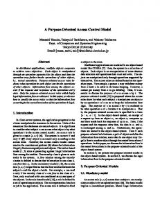
Fig. 1. Example of the experimental Heat Release Rate for Diesel HCCI combustion, showing the different stages: (a) first stage of combustion (cool-flame); (b) main combustion, fast reaction rate; (c) main combustion, slow reaction rate.
A typical experimental heat release rate curve for Diesel HCCI combustion is characterized by two different stages, as shown in Figure 1. This behavior for HCCI combustion has been thoroughly described and also demonstrated for several cases and for most liquid fuels [4], [14]. Considering the HCCI combustion of Diesel type fuels, experimental
(7)
Each of the three function is described according to the Wiebe formulation [11]: � �mi +1 � � ϑ − ϑ0i , i = 1, 2, 3. (8) xi (ϑ) = 1 − exp −ai ∆ϑi In particular, the first burning function is used to model the initial stage of the combustion (cool-flame reactions), while a linear combination of two is employed to describe the main part of the process. In this case the start of combustion will be the same for both functions, i.e., ϑ02 = ϑ03 . The approach adopted is consistent with the phenomenology of the Diesel fuel HCCI combustion process and proved to be a successful modeling methodology, leading to a good approximation of the experimental behavior with a limited number of model parameters to determine [4]. In detail, each function xi (ϑ) requires the parameters ai , mi and the duration of combustion ∆ϑi to be determined from the available data, together with the factors α and β which correspond to the fractions of the overall heat release generated in the first and second combustion respectively. Another extremely important feature of the HCCI process is the start of combustion ϑ0i , which is mainly driven by chemical kinetics, i.e., by gas composition, temperature and pressure. Since HCCI combustion chemistry can be described as a two-step mechanism, the phenomenon of autoignition is modeled by two starts of combustion, assuming the second and third components of (7) occurring at the same crank angle. The start of the first stage of combustion is determined by defining a reaction rate equation after Arrhenius [3], which depends on the mixture density and temperature, and the concentration of fuel and oxygen present at the start of ignition: A Ea AR(ϑ) = [O2 ]−0.53 [F uel]0.05 ρ0.13 exp( ), (9) ω RT where A is a parameter to be optimized on experimental data. In general, the activation energy Ea depends mainly on the characteristics of the fuel and the combustion mode (constant volume or pressure), and in the present work is assumed constant [11], [12]. According to [13], the threshold value of (9) is defined by the following relation: ϑ� SOC
IV C
1 dϑ = 1. AR(ϑ)
(10)
For the second start of combustion, a simple temperature threshold is applied, as suggested in [9]. The main combustion reactions are assumed to start once the in-cylinder
4448
temperature reaches a threshold value which is a function of EGR and Air/Fuel Ratio. III. M ODEL C ALIBRATION The combustion model described above was calibrated on experimental data sets obtained on a single-cylinder DI Diesel engine equipped with an external fuel atomizer to operate in HCCI mode. The engine data, together with the experimental setup, are thoroughly described in [6]. The calibration set is composed by sets of data chosen from the available experiments considering different values of the main control parameters (i.e., intake temperature, EGR ratio, Air-Fuel ratio and boost pressure). For each case, starting from the analysis of cylinder pressure data, an inverse thermodynamic calculation based on the assumptions listed above allows one to obtain the apparent net heat release rate [17]. This function is used to calibrate the heat transfer submodel assuming that from the angle where the apparent net heat release rate becomes negative to the exhaust valve opening, the heat transfer is dominant on the heat release in the energy equation: � � du dV ˙ Qw = −ω M . (11) +p dϑ dϑ The result derived from experimental data is then compared to the one calculated with the heat transfer submodel and the value of the three parameters in (4) and (5) are determined for each case by a least-square fitting procedure. The final values of the parameters are obtained by averaging the results for the different cases.
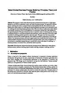
balance, the magnitude of heat transfer is very consistent, its ratio always around 30 − 35% for all the tested engine conditions (Figure 2). This behavior is typical of HCCI combustion, which takes place in all the combustion chamber volume instead of a confined flame front as in traditional SI or CI engines. Figure 2 shows also how the heat released from combustion is extremely advanced, so that the pressure peak occurs around the TDC position. As reported also in [3], [4], [18] and [15], the observed behavior is a feature of HCCI combustion of Diesel fuel, and is substantially different from applications involving other kinds of fuels (examples can be found in [19] and [20]). It is worth to remark that HCCI combustion can be performed only at low and medium load conditions where, usually, pressure peaks are quite close to TDC position resulting in lower engine efficiency. The accuracy of the heat transfer model can be verified by evaluating the combustion efficiency and comparing the value with the experimental one. With some approximation, the combustion efficiency can be calculated by integrating the gross heat release rate function from intake valve closing to exhaust valve opening and comparing the resulting value with the total energy available for the combustion: � EV O dQg IV C ηc = (12) Mf uel LHVf uel For the implementation of combustion efficiency in the cycle model, especially with reference to (6), the calculated values obtained for the calibration data set have been mapped as a function of the Air-Fuel ratio. The combustion efficiency can also be approximated starting from the experimental data, and in particular from the exhaust gas composition. Considering the energy losses associated to the incomplete combustion products (mainly CO and unburned hydrocarbons), and comparing them to the energy associated to the trapped fuel mass yield the following relation [19]: ηc = 1 −
Fig. 2. Results of the inverse calculation on the experimental in-cylinder pressure data.
This preliminary step allows one to calculate the apparent gross heat release which, according to (6), yields the fuel burning rate. This procedure showed also that, in the energy
MCO LHVCO + MHC LHVf uel Mf uel LHVf uel
(13)
In this case, the hydrocarbons emissions were assumed to have the same composition and lower heating value as the fuel. This may not be entirely correct, but the assumption is compatible with the approximated approach adopted. For all of the conditions considered during the calibration, the difference between the calculated and experimental combustion efficiencies was always below 5%, which indirectly proves the accuracy of the heat transfer model adopted. Once the gross heat release is obtained, a nonlinear leastsquares optimization procedure allows one to determine all the remaining parameters, with respect to the Wiebe functions (where three constants are needed for each function, together with the two factors α and β), and the submodel for the calculation of the start of combustion (which requires one parameter). The results of the optimization procedure
4449
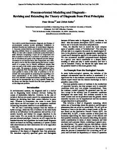
Fig. 3.
(a) 0% EGR, 50 AFR, 1bar pb
Results of the Wiebe functions optimization.
are shown in Figure 3 for one of the calibration data sets (1.4bar IMEP, 0% EGR, 66.7 Air/Fuel Ratio). The optimized values of the twelve parameters are then mapped as linear functions of the main control parameters (EGR ratio, Air-Fuel ratio and boost pressure), by means of a leastsquare fitting procedure. The simple multilinear variation of the parameters is strictly correlated to the sparse nature of the experimental data available. A thorough calibration, possibly based on stochastic techniques, will be made as soon as more experimental data are available.
(b) 60% EGR, 22 AFR, 1bar pb
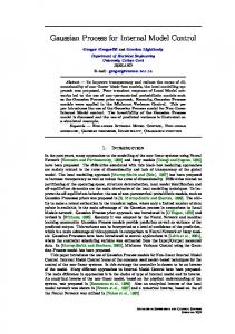
IV. M ODEL VALIDATION AND A PPLICATIONS After the identification and calibration procedure, the model is then validated on a different data set chosen again among the experimental points available. As an example, Figure 4 reports the comparison between the experimental and calculated apparent gross heat release and in-cylinder temperature and pressure for different conditions of the validation set. The comparison was made keeping the engine speed and BMEP at constant values of 2000rpm and 1.6bar respectively, and operating on Air/fuel Ratio, EGR and boost pressure. The agreement found is always satisfactory, considering the simplified approach adopted. The calculated RMS errors on the cylinder pressure traces are always below 7%. Moreover, the limited complexity of the model and the short calculation time suggest several applications for HCCI combustion control. Several simulations were then made to evaluate the influence of the control parameters on the combustion process. Figures 5 and 6 report the effects of EGR ratio and boost pressure variations on the heat release, temperature and pressure, assuming constant engine speed, Air-Fuel ratio and boost pressure. The predicted results agree with the experimental analysis previously performed [6] and show that increasing EGR has the effect of retarding the start of combustion and increasing its duration. The first effect is a consequence of the higher heat capacity of the exhaust gas, which delays the mixture from reaching the conditions to initiate the cool flame combustion. Furthermore, increasing EGR reduces the oxygen concentration, which decreases the reaction rate. This results in cooler temperatures after the
(c) 0% EGR, 62 AFR, 1.4bar pb Fig. 4. Results of the validation procedure in three operating conditions.
cool flame combustion, which cause the delay of the onset of the main combustion event. On the other hand, increasing the boost pressure has the effects of advancing and incrementing the cool-flame heat release. This is a consequence of the higher density of the trapped mass and can be captured only with the submodel based on the Arrhenius rate equation. The increment of gas temperature due to the cool-flame reactions advances also the onset of the main combustion, as well as the in-cylinder pressure peak. This could result in low thermal efficiency and low power output compared to traditional DI Diesel combustion.
4450
of HCCI combustion. R EFERENCES
Fig. 5.
Fig. 6.
Effects of EGR variation on combustion.
Effects of boost pressure variation on combustion.
V. C ONCLUSIONS The proposed work describes a Control-Oriented model of the combustion process in HCCI Diesel engines with external mixture preparation. The approach adopted led to a thermodynamic, singlezone model which describes the combustion not by dealing with the complex chemistry of HCCI autoignition but by defining an apparent heat release through the combination of three Wiebe functions. The adopted methodology led to a very simple, flexible and fast model, which can be considered a useful development tool for all the possible applications related to HCCI engines control and diagnostics. The model was then validated on experimental data obtained on a single-cylinder DI Diesel engine equipped with an external fuel atomizer to operate in HCCI mode. In any of the test cases, the calculated results were fully satisfactory, giving good agreement with the experimental data. Moreover, the model proved to successfully predict the effect of the main control parameters on the development
[1] S. M. Aceves, D. L. Flowers, J. M. Frias, J. R. Smith, R. Dibble, M. Au, and J. Girard, “HCCI combustion: Analysis and experiments,” Proc. of SAE Government Industry Meeting and Exposition, 2001, SAE Technical Paper 2001-01-2077. [2] R. Thring, “Homogeneous charge compression ignition (HCCI) engines,” Proc. of SAE International Fall Fuels and Lubricants Meeting and Exhibition, 1989, SAE Technical Paper 892068. [3] T. W. Ryan and T. J. Callahan, “Homogeneous charge compression ignition of diesel fuel,” Proc. of SAE International Spring Fuels and Lubricants Meeting and Exposition, 1996, SAE Technical Paper 961160. [4] R. H. Stanglmaier and C. E. Roberts, “Homogeneous charge compression ignition (HCCI): Benefits, compromises and future engine applications,” SAE International Fall Fuels and Lubricants Meeting and Exhibition, 1999, SAE Technical Paper 1999-01-3682. [5] A. W. Gray and T. W. Ryan, “Homogeneous charge compression ignition of diesel fuel,” Proc. of SAE International Spring Fuels and Lubricants Meeting and Exposition, 1997, SAE Technical Paper 971676. [6] S. Midlam-Mohler, Y. Guezennec, G. Rizzoni, S. Haas, H. Berner, and M. Bargende, “Mixed-mode HCCI/DI with external mixture preparation,” FISITA 2004 World Automotive Congress, 2004. [7] S. B. Fiveland and D. N. Assanis, “A four-stroke homogeneous charge compression ignition engine simulation for combustion and performance study,” SAE 2000 World Congress, 2000, SAE Technical Paper 2000-01-0332. [8] N. Komninos, D. Hountalas, and D. Kouremenos, “Development of a new multi-zone model for the description of physical processes in HCCI engines,” SAE 2004 World Congress and Exhibition, 2004, SAE Technical Paper 2004-01-0562. [9] G. M. Shaver, J. Gerdes, P. Jain, P. A. Caton, and C. F. Edwards, “Modeling for control of HCCI engines,” Proc. of American Control Conference, pp. 749–754, 2003. [10] D. Rausen, A. Stefanopoulou, J.-M. Kang, J. Eng, and T.-W. Kuo, “A mean-value model for control of homogeneous charge compression ignition (HCCI) engines,” Proc. of American Control Conference, 2004. [11] J. B. Heywood, Internal Combustion Engine Fundamentals. McGraw-Hill, 1988. [12] D. R. Lide, CRC Handbook of Chemistry and Physics. CRC Press, 1995. [13] R. Stone, Introduction to Internal Combustion Engines. SAE International, 1995. [14] S. Tanaka, F. Ayala, J. Keck, and J. Heywood, “Two-stage ignition in HCCI combustion and HCCI control by fuels and additives,” Combustion and Flame, vol. 132, no. 1, pp. 219–239, 2003. [15] Z. Peng, H. Zhao, and N. Ladommatos, “Effects of air/fuel ratio and EGR rates on HCCI combustion of n-heptane, a diesel type fuel,” SAE 2003 World Congress, 2003, SAE Technical Paper 2003-01-0747. [16] D. Kawano, H. Naito, H. Suzuki, H. Ishii, S. Hori, Y. Goto, and M. Odaka, “Effects of fuel properties on combustion and exhaust emissions of homogeneous charge compression ignition (HCCI) engine,” SAE Spring Fuels and Lubricants Article and Exhibition, 2004, SAE Technical Paper 2004-01-1966. [17] H. Zhao and N. Ladommatos, Engine Combustion Instrumentation and Diagnostics. SAE International, 2001. [18] S. Kook, J. Kong, K. Min, and C. Bae, “Homogeneous charge compression ignition engine with two-stage diesel fuel injection,” THIESEL 2004 Conference on Thermo and Fluid Dynamic Processes in Diesel Engines, 2004. [19] A. Helmantel and I. Denbratt, “HCCI operation of a passenger car common rail DI diesel engine with early injection of conventional diesel fuel,” SAE 2004 World Congress and Exhibition, 2004, SAE Technical Paper 2004-01-0935. [20] M. Au, J. Girard, R. Dibble, D. Flowers, S. Aceves, J. MartinezFrias, R. Smith, C. Seibel, and U. Maas, “1.9-liter four-cylinder HCCI engine operation with exhaust gas recirculation,” SAE International Spring Fuels and Lubricants Meeting and Exposition, 2001, SAE Technical Paper 2001-01-1894.
4451