When designing the control of the locomotion of a legged robot on difficult ...... posture with all feet on ground after a few seconds of rivalry between leg and body ...
A Control Structure for the Locomotion of a Legged Robot on Difficult Terrain* Enric Celaya and Josep M. Porta Institut de Robòtica i Informàtica Industrial (UPC – CSIC) Gran Capità 2–4, 08034–Barcelona, SPAIN
Header The control of a legged robot walking on difficult terrain demands the development of efficient and reliable algorithms to coordinate the movement of multiple legs according to a diversity of requirements. We present a control structure, implemented on a six-legged robot, in which the aspects of stability, mobility, ground accommodation, gait generation, and robot heading are integrated in a coherent and simple way. Key Words: - Rough terrain walking. - Posture control. - Terrain adaptation. - Gait generation. - Six-legged robots.
1
Introduction
With an appropriate control of leg movements, a legged robot can climb steps, cross ditches, and walk on extremely rough terrain in which, due to ground irregularities, the use of wheels would not be feasible. As a counterpart, an important drawback of legged locomotion when compared with wheeled locomotion, is the much higher complexity involved in its control, even in the case of completely flat ground. Due to the large number of degrees of freedom (DOF) of a legged robot and the complexity of legged locomotion, human real-time control of individual joint or leg movements is almost impossible in practice [7]. This means that a walking machine, even if it is human driven, has to show autonomous behavior at least at the levels of joint actuation and leg coordination, providing automatic terrain adaptation and body stabilization. Until now, the lack of reliable and efficient algorithms for adaptive walk control on difficult terrain has made the use of legged locomotion impractical for many applications that, in principle, could benefit from it.
*
This work has been partially supported by the Comisión Interministerial de Ciencia y Tecnología (CICYT), under the project “Navegación basada en visión de robots autónomos en entornos no estructurados” (TAP971209) and by a grant from the Comissionat per a Universitats i Recerca de la Generalitat de Catalunya to the second author.
1
Since the capability to deal with difficult terrain is the key feature that gives interest to legged robots, it makes little sense to develop walking controllers under the assumption of smooth terrain. On the contrary, the presence of arbitrary irregularities in the ground should be considered as the typical situation, in which obstacles of any size, including walls and cliffs, may appear anywhere. This article presents a control structure for the locomotion of legged robots developed under the assumption of difficult terrain from the very beginning. We believe that, since the aspects of ground accommodation and body stabilization are as important when the robot stays still as when it is walking or climbing, they must be considered as more basic, corresponding to a lower level and, therefore, have to be addressed in the first place. This contrasts with some approaches to robot walking on rough terrain, which begin by developing fixed gait pattern generators able to work on flat ground that are then enhanced to cope with irregular terrain by including sensory feedback [2], [4], [6]. The control structure we present is intended to be of general applicability to robots with a minimum of four legs to allow statically stable walking, three independent DOF on each leg to provide a three dimensional workspace for each foot, and a minimal set of sensorial capabilities, such as proximity, contact, or force sensing on legs and different parts of the body. The case of robots with 2-DOF legs is also addressed by adapting the 3-DOF case via some approximations. We have implemented and tested the proposed control architecture on Genghis II, a commercially available robot with six 2-DOF legs. Genghis II provides a minimal platform on which to test the proposed control structure and we hope that the fact that it is a standard robot will make the comparison with other approaches easier. In the next section, we propose a hierarchical decomposition of the task of walking on difficult terrain in three levels: Posture control, terrain adaptation and movement generation. Each level is explained in detail in Sections 3, 4 and 5, respectively. In Section 6, the control structure is applied to Genghis II and several implementation issues are discussed. Section 7 presents the results of the tests performed on the robot. We conclude with Section 8.
2
The control structure
When designing the control of the locomotion of a legged robot on difficult terrain there are many aspects that have to be dealt with simultaneously and whose actions interfere with each other. Thus, for example, movements of legs must be carefully coordinated in order to advance the body without causing feet slippage; at each step, an appropriate foothold has to be found, avoiding invalid ground patches for placing a foot and keeping a sufficient range of leg mobility for future motion; body attitude must be set according to the terrain profile to avoid collisions with obstacles, keep stability, etc. To deal with such a complexity we have followed the behavior-based approach of the Subsumption Architecture [1], in which the control process is decomposed in hierarchically organized modules running in parallel, each one providing a specific competence that solves some aspect of the control task. In this approach, processes of a given level perform their actions unconcerned with the operation of higher level ones, at the same time as they take advantage of the competences provided by lower level processes, sometimes governing their workings by providing specific inputs to them. To establish a hierarchical decomposition based on sensible grounds we take into account two fundamental aspects: ·
Task-dependence: While some competences are devised to achieve specific, temporarily assigned tasks, so that they must be active only eventually (e.g., advancing in a desired direc-
2
·
tion, approaching a target, etc.), there are also competences that are task-independent and should be active at any time (e.g., avoiding collisions with objects, maintaining good stability, etc.). Use of sensorial information: While most competences require the use of sensors to get information from the environment (e.g., accommodation of feet on ground, collision avoidance, etc.), some of them do not require external sensing and can be done on the sole basis of proprioceptive information (e.g., improving the positioning of the body according to the current locations of feet).
The consideration of these two aspects carries us to the definition of the following three levels of decomposition: 1. Proprioceptive level (Task independent, no sensorial input) At this level, only internally available information of the robot's own state, is used. It can be seen as a level of self-regulation. The functionality provided by this level is posture control, and its purpose is to place the body in the most appropriate position given the current feet locations. 2. Environment driven level (Task independent, sensorial input) This level responds directly to the present conditions of the environment as detected through sensors. This is basically a reactive level. The functionality provided by this level is terrain adaptation, and its purpose is to accommodate leg and body positions to the shape of the terrain and to react to collisions with obstacles. 3. Task driven level (Task dependent) This level responds to externally supplied or internally defined purposes of the robot, which are dependent on the specific task to be done. This is basically a deliberative level. The functionality provided by this level includes a movement generation module that consists of mechanisms for gait generation and for speed and heading control. Particular navigation tasks can be implemented by adding higher level processes to generate appropriate speed and direction commands. In the next sections, each of these three levels is discussed in detail.
3
Proprioceptive level: Posture control
Robot stability and mobility are two aspects of the control of a walking robot whose improvement is always desirable, independently of the specific task assigned to the robot. Though, in general, information provided by sensors should have to be taken into account, stability and mobility can be improved, to some extent, even in the absence of sensorial information: Robot stability is improved by increasing the separation between feet and approaching the robot's center of gravity (COG) to the geometric center of the feet positions. Robot mobility is improved by raising the body with respect to feet to increase ground clearance, and keeping feet away from the boundaries of their respective workspaces to allow a wide range of movement in any direction. Thus, we define the purpose of the proprioceptive level as that of adopting an optimal position of the body with respect to the current feet locations so that robot stability and mobility are improved. To
3
avoid the undesirable effects that could result from moving a supporting leg without using sensorial information, leg movements at this level have to be performed in a coordinated way so that the position of each foot in the environment remains unchanged. The process of modifying the position of the body in this way is what we call posture control. Posture control has received insufficient attention in the literature of legged robots. Most authors have considered the problem of the control of body altitude and attitude as independent of that of body motion. Here we want to stress that both problems are particular instances of posture control, and can be dealt with in a unified way. In order to formalize the problem of posture control we have to introduce some definitions: Definition 1: The configuration polygon of the robot is a spatial polygon (i.e., a polygon not necessarily contained in a single plane) whose vertices correspond to the positions of the extreme points of legs, or feet. The configuration polygon must not be confused with the more commonly used support polygon or support pattern, which involves only supporting feet and is contained in a horizontal plane. In contrast, the configuration polygon involves all feet and, since it can be determined from only the relative positions of feet with respect to the body, makes no use of sensorial information from the environment. Definition 2: The posture P of an n-legged robot is the set of positions {pi} (i=1,...,n) taken by feet with respect to the body. Note that the posture of the robot uniquely determines the shape and position with respect to the body of the configuration polygon, but the same configuration polygon can be placed at different positions with respect to the body, giving rise to different postures of the robot. Definition 3: Two postures are compatible if they define the same configuration polygon. Definition 4: A conservative gesture is a coordinated movement of legs such that the configuration polygon is displaced with respect to the body without changing its shape. According to these definitions, a conservative gesture drives the robot through a continuous set of mutually compatible postures. Definition 5: The distance DP,Q between two postures P and Q is the sum of the squared distances between the positions (with respect to the body) of each foot in both postures. Formally, if P={pi} and Q={qi} (i=1,...,n), then: D P ,Q =
åp n
i
- qi
2
.
(1)
i =1
Note that there is always a non-null distance between two different postures, even if they are compatible. Definition 6: The reference posture of a robot is that which, in general conditions, provides a preferred combination of stability and mobility.
4
In general, these two aspects are in conflict [7] and must be traded-off: while mobility improves when each foot is near the center of its workspace, stability increases when legs are extended towards their distal bounds. The reference posture has to be established for each particular robot structure, and is not completely detached from user preferences. As an example, we define the reference posture for our six-legged robot as that shown in Figure 1, in which legs are orthogonal to the longitudinal axis of the robot and form an angle with ground that provides enough body clearance.
Z
Rz
Y X
5
6 3
4
Rx 1
2
Rx Ry
Ry
Figure 1: REFERENCE POSTURE FOR THE SIX-LEGGED ROBOT GENGHIS II.
As stated above, the purpose of posture control is to improve robot stability and mobility while keeping the configuration polygon unchanged. Therefore, what we need now is a way to determine which one, among all the postures associated with an arbitrary configuration polygon, is considered to provide the best combination of stability and mobility. For this, we will use the trade-off implicitly established by the reference posture, choosing the posture that is closest to it, as stated in the following definition: Definition 7: The optimal posture of the robot for a given configuration polygon is the posture that minimizes its distance to the reference posture while keeping the configuration polygon invariant. Thus, the goal of posture control is to drive the robot, using only conservative gestures, to the optimal posture for the current configuration polygon. The effect of posture control can be illustrated with a physical analogy (Figure 2): Assume that each foot is rigidly attached to its current position in the environment, and that the configuration polygon corresponding to the reference posture is rigidly attached to the body. If each foot position is connected with its corresponding vertex of the polygon of the reference posture with a spring that exerts an attractive force proportional to its length, then the body will move to the minimum energy configuration in which all forces and torques add to zero. The resulting positions of feet with respect to the
5
body in the equilibrium situation correspond to the optimal posture for the current configuration polygon.
Figure 2: PHYSICAL INTERPRETATION OF THE OPTIMAL POSTURE (IN TWO DIMENSIONS). At left, a six-legged robot in an arbitrary posture is shown. Actual robot legs are represented in thick lines. Big dots correspond to actual feet positions, which must remain fixed. In thin lines, the body of the robot is represented with imaginary rigid legs positioned in the reference posture. Springs connecting the vertices of the actual and reference feet positions exert a force and torque on the body of the robot. The right figure shows the position to which the springs would drive the body, and corresponds to the optimal posture.
Next, we show how to determine the optimal posture corresponding to a configuration polygon and a path to reach it from the current posture P. The positions pi of feet in posture P are related with positions qi in a compatible posture Q through the spatial transformation T(W)ÎSE(3) experimented by the configuration polygon, where W=(x, y, z, f, q, y) is a vector of parameters, and T(W)=Tz(z)Ty(y)Tx(x)Rz(f)Ry(q)Rx(y), where Tx(·), Ty(·), Tz(·), Rx(·), Ry(·) and Rz(·) are translations along, and rotations about, the corresponding axes of the reference frame of the body. Expressed in homogeneous coordinates, the relation between pi and qi can be written as: é q xi ù écos f - sinf 0 x ù é cos q 0 sinq 0ù é1 0 0 0ù é p xi ù ê iú ê ú ê ú ê úê i ú êq y ú = ê sinf cos f 0 y ú ê 0 1 0 0ú ê0 cosy - siny 0ú ê p y ú (2) ê q zi ú ê 0 0 1 z ú ê - sinq 0 cos q 0ú ê0 siny cosy 0ú ê p zi ú ê ú ê úê úê úê ú 0 0 1û ë 0 0 0 1 û ë0 0 0 1û êë 1 úû êë 1 úû ë 0 The distance DQ,R from posture Q to the reference posture R can be seen as a function of the transformation parameters W given by:
6
DQ , R (W) =
åq n
i
-r
i
2
=
å [(q n
i =1
i =1
i x
- rxi ) 2 + (q iy - ryi ) 2 + (q zi - rzi ) 2 ].
(3)
Using (2) and (3), we can find the components of the gradient vector of the distance function in posture P: n n ¶DQ , R ¶DQ , R = 2 ( p xi - rxi ) = 2 (ryi p zi - rzi p iy ) ¶x ¶y i 1 i 1 0 0
å
¶DQ , R ¶y
=2 W=
¶DQ , R ¶z
0
å n
å
=
W=
¶DQ , R ¶q
( p iy - ryi )
i =1
0
=2 W=
å
=
W=
n
( p zi
-
¶DQ , R ¶f
rzi )
i =1
å (r p
i x
- rxi p iz )
å (r p
i y
- ryi p ix )
=2 W=
0
0
i z
(4)
i =1
=2 W=
n
n
i x
i =1
For the optimal posture, the six gradient components of equation (4) must vanish. It can be shown that the function DQ,R has a single relative minimum, and thus, an iterative gradient-descent process can be used to reach the optimal posture. Figure 3 shows some examples of the postures reached by gradient descent from different initial postures.
B
A
C
Figure 3: THE EFFECT OF POSTURE CONTROL. A) From an arbitrary posture (dashed figure) with a configuration polygon close to the reference one, the robot approaches to the reference posture. B) Typical situation in the process of walking. In the dashed figure, front right, middle left and rear right legs have recently stepped and are in an advanced position with respect to the body. By the effect of posture control, the body moves forward and slightly rotates to the left. Front left, middle right and rear left legs are moved backwards to an appropriate position to perform the next step. C) An advanced position of left legs with respect to right legs produces a rotation of the body to the right.
7
3.1
Executing conservative gestures: Balances
To execute a conservative gesture in a real robot, each foot should follow a trajectory in coordination with all other feet, so that the configuration polygon is not deformed in the process. In practice it will be necessary to approximate such a trajectory by computing, for each foot, a series of points in the path from posture P to Q and simultaneously driving all feet through them. The specific trajectory to follow from P to Q can be arbitrarily chosen within the six-dimensional space of compatible postures.
A convenient way to implement the posture control mechanism is to build six separate processes, that we call balances, each of which controls the movement in one of the six DOF. Thus, each balance is continually monitoring one component of the distance gradient vector given in equations (4) and, if it is different from zero, the balance performs a small displacement of all feet along the corresponding DOF in the direction in which the distance to the reference posture decreases, which is determined from the sign of the corresponding component of the distance gradient vector. Since the action of balances is performed through successive small displacements, we can approximate them by straight line movements in the directions given by the partial derivatives of qi with respect to the six parameters. Computing these derivatives from equation (2) and evaluating them at the origin, we have: é 0 ù é1ù ¶q i ¶q i ê ú ê ú = ê0ú = ê- p zi ú ¶x ¶y 0 0 ê p iy ú êë0úû ë û W=
¶q ¶y
W=
i
¶q i ¶z
W=
W=
0
0
é0ù = êê1úú êë0úû
¶q ¶q
W=
0
é0ù = êê0úú êë1úû
¶q i ¶f
W=
0
i
é p zi ù ê ú =ê 0 ú ê- p xi ú ë û i é- p y ù ê ú = ê p xi ú ê 0 ú ë û
(5)
Thus, each balance performs simultaneous short movements of all feet in the directions given by the corresponding vectors of equations (5). Each of the balances implements an independent gradient-descent process for its corresponding DOF. It can be shown that such approach will drive to the global minimum without a need for coordination of the different balances, provided the individual displacements performed by each balance are sufficiently small. Balances provide a coordination mechanism for leg movements that greatly simplifies the performance of conservative gestures, and can be used by higher level modules to execute body movements in the following way: Adding a bias to one of the equations (4) will produce a displacement of the target position causing the corresponding balance to displace the body along the associated DOF, just as if an external force or torque had been applied to it.
8
3.2
Posture control in a robot with 2-DOF legs
For a robot with only 2-DOF legs, the set of conservative gestures that can be performed is very restricted or even null, depending on its mechanical design. This means that body movements along some of its DOF (or even all of them) are not possible without changing in some way the configuration polygon, and conservative gestures must be approximated by non conservative ones. Next, we consider the particular case in which legs are only allowed to move in the x and z directions, their y coordinates with respect to the body, p iy , being the constant values ryi . With this assumption, the distance gradient equations (4) used to reach the optimal posture become: n n ¶DQ , R ¶DQ , R = 2 ( p xi - rxi ) = 2 ryi ( p zi - rzi ) ¶x ¶y i 1 i 1 0 0
å
¶DQ , R ¶y ¶DQ , R ¶z
å
=
W=
¶DQ , R ¶q
=0 W=
0
å
=2 W=
n
( p zi
-
¶DQ , R ¶f
rzi )
i =1
0
=
W=
å (r p n
=2 W=
i x
- rxi p iz )
(6)
i =1
0
=2 W=
i z
å r (r n
i y
i x
- p ix )
i =1
0
and the direction vectors of the balances given in equations (5) become: é0ù é1ù ¶q i ¶q i =ê ú =ê iú ¶x ¶y ë0û ë ry û 0 0 W=
¶q ¶y
W=
W =0
é0ù =ê ú ë0û
¶q ¶q
W =0
0
é0ù =ê ú ë1û
¶q i ¶f
W=
i
¶q i ¶z
W=
i
0
é pi ù = ê zi ú ë- p x û é- r i ù =ê yú ë 0 û
(7)
where only the x and z components of the displacement vectors are written, since no displacement along the y direction is possible. This is also reflected by the fact that the vector corresponding to the balance for the y translations, as well as the corresponding gradient component, vanish. Comparing (5) with (7) it can be seen that only displacements along x and z and rotations about y remain the same and, therefore, these are the three only DOF along which exact conservative gestures can be performed. Summarizing, in the case of a robot with legs able of only x and z movements, only five balances can be used, and the conservative gestures corresponding to rotations about x and z are only approximately correct, since they change somehow the configuration polygon.
4
Environment driven level: Terrain adaptation
The purpose of this level is to reactively adapt feet positions to the actual ground profile, respond to collisions with obstacles, and improve robot stability according to the information provided by sensors. For the description of the different mechanisms that constitute this level, we will group them according to the kind of sensorial information they use. Mechanisms involving leg-related sensorial information will trigger leg positioning movements, resulting in a change of the configuration polygon.
9
In contrast, mechanisms involving body-related sensorial information will trigger body positioning movements accomplished by means of conservative gestures.
4.1
Leg positioning mechanisms
To achieve ground contact with legs at any time, the configuration polygon has to be changed to fit the ground profile. For this purpose, we consider the following mechanisms: ·
·
·
Ground accommodation An effective mechanism to keep feet on ground consists in monitoring the weight supported by each leg and lowering it when the sensed force is null or too low. This constitutes a mechanism of active compliance to distribute forces among legs that was already used in [5]. To avoid an uncontrolled drift in the vertical direction, a constant control of the body height is necessary. Note that the posture control level already provides this functionality, specifically through the balance corresponding to the z-translation. Foothold searching If, in the process of ground accommodation, a leg reaches its lowest position without achieving ground contact, a foothold has to be sought in the vicinity of the current foot position. This can be done by performing progressively wider exploratory movements in a horizontal direction until supporting ground is detected. Leg collision avoidance If a collision with an obstacle is detected by a leg that moves in a horizontal direction, a skipping maneuver has to be executed, consisting in a short movement in the opposite direction, an elevation of the leg by a certain amount, and a reissuing of the horizontal movement. This action may have to be repeated several times if the collision persists.
It is worth noting that when a leg positioning movement displaces a leg with respect to the body in a given direction, the posture control level reacts by moving the other legs in the opposite direction. As a result of this, the body is displaced in the same direction as the original leg displacement, thus contributing to it. This can be seen as a form of inter-leg cooperation.
4.2
Body positioning mechanisms
Based on the kind of sensors available in our robot, we have devised the following mechanisms for body positioning: ·
Slope adaptation If information about body attitude is available, for example by means of an inclinometer (as in our case), the stability of the robot can be improved by translating the body in the x-y plane, so that the vertical projection of its COG gets closer to the center of the configuration polygon. For some applications, it may also be desirable to keep the body horizontal. However, if this is not necessary, having the body parallel to the local ground is preferred since, in general, this improves the mobility of the robot.
10
·
·
Obstacle avoidance If an obstacle is detected in front of the robot or in the lower part of the body, its elevation should be temporarily increased to avoid the collision. The attitude of the body may also be modified accentuating the elevation of the body by the side in which the obstacle is detected.
Extreme situations When one of the leg positioning mechanisms drives a leg until an extreme position, a body positioning movement should be performed to allow the leg to reach farther. For instance, the body should be made to descend when a leg reaches its lower position without finding a support point, and it should be raised when a leg reaches its highest position trying to avoid an obstacle. A convenient way to execute the conservative gestures required by the body positioning mechanism is to add a force or torque term to one or more of equations (4) as explained in section 3.1. This form of control yields a harmonious integration of the different body positioning mechanisms, showing the adequacy of the hierarchical organization of the proposed control structure.
5
Task driven level: Movement generation
To carry out a navigation task, a legged robot must be endowed with locomotion capabilities allowing it to advance in an efficient and reliable way in arbitrary terrain conditions, and to respond to commands of speed and direction, either externally provided or autonomously generated. To this end, two mechanisms are included in this level, one for gait generation, and another for speed and heading control.
5.1
Gait generation
Walking is achieved by performing successive leg movements, or steps, in a given sequence, which constitutes the gait. Periodic gaits can be obtained from very simple control rules, and they are completely appropriate to walk on smooth terrain. However, when terrain conditions are adverse, a fixed periodic gait becomes too restrictive, and a more flexible pattern, or free gait, has to be adopted. The most important aspect a gait generation strategy has to take into account is robot stability. For a statically stable locomotion, it must be granted that a sufficient set of legs stay on ground supporting the body at any time. In general, a minimum supporting set is formed by three legs defining a triangle that contains the vertical projection of the COG of the robot. In the case of most six-legged robots, this requirement can be satisfied by observing the following rule: Rule 1: Never have two neighboring legs raised from the ground at the same time. Here, we assume that two legs are neighbors when they appear one next to the other in a closed circuit around the robot. The fulfillment of Rule 1 assures that, at any time, the robot will be supported by at least three nonneighboring legs, forming a triangle that we assume will always contain the vertical projection of the COG. The violation of Rule 1, however, will result in a situation in which two neighboring legs are out of the ground at the same time, most probably leaving the robot in a very unstable situation. For a robot with more than six legs, Rule 1 is also sufficient to grant robot stability, though in this case a less
11
restrictive condition could easily be devised. Conversely, in a four-legged robot, more restrictive rules must be used. In the following, we will limit our discussion to six-legged robots and will consider Rule 1 as a necessary and sufficient condition for stability, provided the posture control and terrain adaptation mechanisms constituting the lower levels of our control structure are active. According with Rule 1, a leg can be raised to make a step only while its two neighboring legs are in contact with ground. However, Rule 1 by itself is not enough to determine a gait. It leaves undetermined which one of a pair of neighboring legs should actually perform a step when Rule 1 allows both of them to be raised. To resolve the conflict, we resort to a simple strategy captured in the following rule: Rule 2: A leg should perform a step when this is allowed by Rule 1 and its two neighboring legs have stepped more recently than it has. This is a local rule that forces the alternation of the steps of any pair of neighboring legs. While this requirement is reasonable for walking straight on flat ground, it can be too restrictive in difficult terrain or while executing a change in direction. In these cases, the step sequence can be decided by higher level processes, and Rule 2 will be used as a default. Rule 2 can be implemented using the following token passing protocol: Each leg shares one token with each of its two neighboring legs. Only legs holding both tokens are allowed to step. As soon as a leg performs a step, it sends the tokens back to its two neighboring legs. Note that, in general, a leg will not be able to step immediately after receiving both tokens, since, due to Rule 1, it should wait until its neighboring legs complete their respective steps and reach the ground to support the body. It is well established [10] that the so called wave gaits often observed in legged animals, constitute the most efficient and stable way to walk on a flat surface. Wave gaits are characterized by a rear to front propagation of stepping actions forming a wave at each side of the body with the same frequency and in opposition of phase. In theory, the complete family of wave gaits can be obtained with Rule 1 and Rule 2 and a proper initial distribution of tokens as, for example, one in which three of the legs hold their two tokens. In practice, the spontaneous occurrence of a wave gait is rather improbable, since this would require steps to be consistently delayed along time. The random differences in the time taken by each leg to reach the ground due to terrain irregularities cause the resulting gait to be non-periodic. However, it can be shown [9] that, if starting from an arbitrary situation, all legs take the same amount of time to reach the ground after making a step (as is likely to happen in smooth ground), a gait in which two sets of three legs alternate in stepping and supporting the body emerges. This gait, called the tripod gait, is the fastest of the wave gaits and is commonly observed in insects walking on smooth surfaces [11]. Note that Rule 1 and Rule 2 are local, in the sense that each leg only needs information concerning its two neighboring legs, and no central scheduler or synchronization process is required.
5.2
Speed and heading control
The gait generation mechanism described above only takes care of the step sequence. The necessary advance movement of the body is automatically produced by the posture control mechanism of the proprioceptive level, in particular by the balance associated with the x-translations that compensates the horizontal forward displacements of the stepping legs with backward displacements of all supporting legs.
12
Assuming a regular periodic gait, if vance speed V is given by:
S
is the average length of steps, or leg stroke, the mean adV=
S bT
(8)
where T is the period of the gait and b is the duty factor, defined as the fraction of the period time a leg spends in the support phase. The speed of the robot can be modified by either delaying the execution of steps (something that happens spontaneously in a difficult environment) or modifying the stroke length. Since the body movement is produced by the balance mechanism, changes in stroke length are automatically accounted for, and do not require any additional consideration. Walking backwards is achieved by simply reversing the direction of the stroke for all legs. However, to perform a sudden inversion of the advance direction, legs should undo their last steps in a sort of temporal inversion of their movements so that the step sequence is also inverted. Such inversion of the step sequence is obtained by a simple exchange of all tokens between neighboring legs, so that Rule 2 is temporary ignored. Turning is achieved by simply using different stroke lengths on both sides of the robot. In this case, the balance associated with the z-rotation automatically produces the appropriate heading of the robot. If Sr and Sl are the stroke lengths of steps of right and left legs, respectively, and noting that the gait generation mechanism assures that, in average, all legs perform the same number of steps in a given period of time, the radius of curvature of the path followed by the center of the body is found to be L (S + S ) r= y r l (9) (S r - S l ) where we have made the simplifying assumption that all feet are at the same distance L from the x-z plane passing through the center of the body. Using Equations (8) and (9) and noting that S = ( S r + S l ) / 2 , the turning speed is found to be: (S - S ) w =V = r l , (10) r 2 L y bT showing that advance and turning speeds can be independently set by adjusting the stroke length of each side. y
6
Implementation on a real robot
The control structure we have described has been implemented on Genghis II, a commercially available six-legged robot. Genghis II's body is about 40 cm long and 15 cm wide. Each leg is approximately 10 cm long and has two DOF: a rotation around a vertical axis fixed to the body and another around a non-fixed horizontal axis. When legs are completely vertical, body clearance is about 8 cm. The robot is provided with force sensors at each joint (actually, it is the current used by each motor what is measured), contact/force sensors all along the lower part of the body, two frontal whiskers to detect contacts, one pitch inclinometer, four infrared sensors, and a set of five pyro sensors. The programming of all control modules has been done in PCBL [8], a programming language we have developed to facilitate the implementation of behavior based controllers according to the main guidelines of the Subsumption Architecture. Originally, the Subsumption Architecture was designed to provide extensibility of processing power by allowing each module to run asynchronously on a differ-
13
ent processor, so that no shared memory between processors was available and only low bandwidth communication lines between them were permitted. When all modules run on a single processor (as in our case), these restrictions become useless and make programming unnecessarily complex. For these reason PCBL allows processes to share memory and to send messages of arbitrary type. Ground contact detection with the force sensors of legs was the most problematic issue we had to address. In fact, the sensor reading is only related with force when the motor is not moving so that monitoring it requires stopping the motor. This prevents the execution of fast descending movements of legs, which would lack force information making the detection of ground contact extremely imprecise and unreliable. On top of the described movement generation modules, we have implemented a simple driving module. By default, the robot follows a straight path at the maximum speed allowed by terrain conditions (no delays other than those produced by legs looking for supporting ground are introduced). Driving commands of speed and direction are provided by a number of additional processes: Contacts detected by whiskers induce a temporary shortening of the stroke length on legs of the opposite side giving rise to a turn in the appropriate direction. When the contact is detected with both whiskers, the result is a progressive decrease in speed and, if the situation is prolonged enough, the robot walks backwards for a while. The reiterative failure of the foothold searching for one of the leading legs is interpreted as the presence of a cliff or a patch of non-rigid ground. In this case, the robot inverts its advance direction for a while, makes a turn of about 90º, and resumes forward walking.
6.1
Implementation of posture control in Genghis II
The mechanical design of Genghis II provides two rotational DOF to each leg, so that feet are restricted to move on approximately spherical surfaces. This fact prevents the execution of parallel displacements and coaxial rotations of two or more feet, as would be needed to perform conservative gestures. Therefore, we need to approximate conservative gestures in some way. If L is the leg length, and assuming that leg i is nearly horizontal and perpendicular to the body, we can approximate displacements of length d in the x direction by rotations of angle a =d /L around the vertical axis. Similarly, displacements of length h in the z direction can be approximated by rotations of angle b =h/L around the horizontal axis. Taking the convention that for the reference posture a = 0 and b i = 0, we have: d i = p xi - rxi » La i (11) h i = p zi - rzi » Lb i . i
i
i
i
i
i
Using these approximations to eliminate p xi and p zi from equations (6) we obtain the following expressions for the distance gradient components: 6 6 ¶DQ , R ¶DQ , R » 2L a i » 2 L ryi b i ¶x ¶y i 1 i 1 0 0
å
¶DQ , R ¶y ¶DQ , R ¶z
å
=
W=
¶DQ , R ¶q
=0 W=
0
» 2L W=
0
=
W=
åbi
¶DQ , R ¶f
6
i =1
14
» 2L W=
0
i z
i =1
0
» 2L W=
å (r a 6
år a 6
i y
i =1
i
i
- rxi b i )
(12)
The direction vectors associated with balances are those given in equations (7) except for the rotation around the y axis, which becomes: é r i + Lb i ù é rzi ù ¶q i »ê zi »ê iú, (13) iú ¶q ë- rx - La û ë- rx û 0 W=
where the last approximation is done because of the impossibility of performing too precise leg movements due to the low resolution with which they can be commanded in Genghis II, and because angles a i and b i are assumed to be relatively small. The resulting set of balances is equivalent to that introduced in [3], whose graphical interpretation is given in Figure 4.
z-translation
x-translation
x-rotation
y-rotation
z-rotation
Figure 4: THE FIVE APPROXIMATE CONSERVATIVE GESTURES FOR A SIX-LEGGED ROBOT WITH 2-DOF LEGS.
7
Experimental results
One advantage of the subsumption-based hierarchical structure of the controller is that the performance of each level can be easily tested simply by deactivating all levels above it. Thus, for example, tests performed at the level of terrain adaptation, with the movement generation modules deactivated, consisted in releasing the robot on an uneven surface and observing if the ground accommodation mechanism was able to achieve ground contact with all legs. Typically, the robot reaches a stable posture with all feet on ground after a few seconds of rivalry between leg and body positioning movements, even with large irregularities in the ground profile. As a representative case, the robot was
15
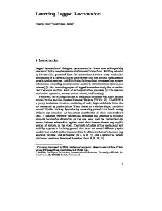
able to accommodate to a flat surface with one leg staying on a step more than 12 cm high. A similar experiment substituting the step by a hole under one leg showed the ability of the robot to accommodate until a depth of more than 12 cm. Tests of the complete controller including the movement generation module, showed that the average speed of the robot on smooth ground is about 5 cm/s, progressively decreasing as the difficulty of the terrain is increased. By setting opposite strokes on legs of both sides, the robot turns around at a speed of about 8º/s. The limiting factor for speed is the slow movement imposed on leg descent in order to reliably detect ground contacts. The effect of the slowness of leg descent on the overall speed of the robot can be appreciated in Figure 5, showing a sample of the actual gait pattern obtained with the robot walking on a smooth surface. In the figure, black lines represent the time during which a leg is performing a step (lift and forward movement). Gray lines correspond to the time during which a leg is not detecting ground contact and is being moved down by the ground accommodation mechanism of the terrain adaptation level. Thin discontinuous lines correspond to the time during which a leg is detecting ground contact. The arrangement of legs in the diagram has been chosen so that adjacent lines correspond to neighboring legs. From the figure, it is clear that accelerating the leg descent movement, and using and alternative ground detection method, for example by using contact sensors, the average speed could be improved in a significant way.
2
1
4
3
6
5 TOP VIEW A
B
C
2 4 6 5 3 1 0
5 Time (in seconds)
10
20
15
25
30
Figure 5: GAIT OBTAINED ON A SMOOTH SURFACE.
It can be seen that the emerging gait is very close to the tripod gait in which steps of legs 1, 4, 5 alternate with those of legs 2, 3, 6 (marks A and B in Figure 5). Note that, even while a leg is actually supporting the body, ground contact detection is occasionally missed, producing a delay in the gait. Thus, in C, legs 2 and 3 are delayed with respect to leg 6 since they must wait until leg 1 acknowledges ground contact. However, after a short number of steps, leg synchronization spontaneously reappears and an almost perfect tripod gait is observed. Figure 6 illustrates the effect of a sudden, externally commanded change of the direction of movement from forwards to backwards. When the inversion in the stroke direction is accomplished, an exchange of tokens between neighboring legs is triggered (mark near sec. 15), so that legs 1, 4 and 5, which had already begun a step, are made to “undo” it and return to their previous positions.
16
2 4 6 5 3 1 0
5 10 20 15 Time (in seconds) Figure 6: EFFECT OF A SUDDEN DIRECTION INVERSION.
Tests in general terrain with all kinds of irregularities showed the ability of the robot to negotiate virtually of kind of difficulties, getting stuck only on some rare occasions in which a foot gets trapped into a narrow cavity. The robot is able to climb up and down vertical steps of more that 10 cm high, which is about the leg length. Figure 7 shows the gait recorded in the presence of an obstacle of about 7 cm high at the left side of the robot. The times at which legs 1, 3 and 5 climb onto the obstacle are marked with A, B and C respectively. Dark gray lines correspond to the execution of the leg collision avoidance mechanism, denoting the presence of the obstacle, which in this case requires two skipping movements of each leg to be overcome. B
A
C
2 4 6 5 3 1 0
5 Time (in seconds)
10
20
15
25
30
Figure 7: GAIT OBTAINED WITH AN OBSTACLE AT THE LEFT.
8
Conclusions
We have presented a control structure for the locomotion of a legged robot on difficult terrain based in a three-level hierarchical decomposition. The first level does not use sensorial information from the outside, and simply reacts to the current locations of feet with respect to the body, trying to reach the posture that best fits with them. Such a mechanism, implemented as a set of balances, is central in the control structure, and is capitalized by the other two levels for their own purposes. It has been realized that the use of balances greatly simplifies the design of higher level mechanisms like terrain adaptation, advance, and heading control. The implementation of this control structure on a six-legged robot shows a good performance in very difficult terrain, even with the limitation of having only 2-DOF legs. In the near future, we expect
17
to implement the proposed control architecture on a robot with 3-DOF legs to further explore its potentialities and possible weaknesses.
References [1] Brooks, R.A. (1986): “A Robust Layered Control System for a Mobile Robot”, IEEE Journal of Robotics and Automation, Vol. RA-2, No. 1, pp. 14-23, March. [2] Brooks, R.A. (1989): “A Robot that Walks; Emergent Behaviors from a Carefully Evolved Network”, Neural Computation, No. 1, pp. 253-262. [3] Celaya, E. and Porta, J.M. (1996): “Control of a Six-Legged Robot Walking on Abrupt Terrain”, 1996 IEEE Int. Conf. on Robotics and Automation. [4] Ferrell C. (1993): “Robust Agent Control of an Autonomous Robot with Many Sensors and Actuators”, M.S. Thesis, MIT. [5] Hirose, S. (1984): “A Study of Design and Control of a Quadruped Walking Vehicle”, Int. Journal of Robotics Research, Vol. 3, No. 2, pp. 113-133. [6] Klein, C.A., Olson, K.W. and Pugh, D.R. (1983): “Use of Force and Sensors for Locomotion of a Legged Vehicle over Irregular Terrain”, Int. Journal of Robotics Research, Vol. 2, No. 2, pp. 317. [7] Orin, D.E. (1982): “Supervisory Control of a Multilegged Robot”, Int. Journal of Robotics Research, Vol. 1, No. 1, pp. 79-91. [8] Porta, J.M. and Celaya, E. (1996): “The behavior language for PC: User's guide”, Technical Report IRI-DT-9602. [9] Porta, J.M. and Celaya, E.: “Gait analysis for six-legged robots”, In preparation. [10] Song, S.M. and Waldron, K.J. (1987): “An Analytical Approach for Gait Study and Its Applications on Wave Gaits”, Int. Journal of Robotics Research, Vol. 6, No. 2, pp. 60-71. [11] Wilson, D.M. (1966): “Insect walking”, Annual Rev. of Entomology, 11, pp. 103-122.
18