rate, low power consumption and long mechanical dura- bility. In addition ... opportunities for embedded systems and laptops to store larger amounts of ...... [13] KFG4GH6x4M 4Gb Flex-OneNAND M-die Datasheet, Samsung Electronics, 2008.
A Cross-Layer Approach for New Reliability-Performance Trade-Offs in MLC NAND Flash Memories
†
C.Zambelli∗, M.Indaco† , M.Fabiano† , S.Di Carlo† , P.Prinetto† , P.Olivo∗ and D.Bertozzi∗ ∗ University of Ferrara, Engineering Department, 44122, Ferrara - ITALY Politecnico di Torino, Department of Computer and Control Engineering, Torino - ITALY
Abstract In spite of the mature cell structure, the memory controller architecture of Multi-level cell (MLC) NAND Flash memories is evolving fast in an attempt to improve the uncorrected/miscorrected bit error rate (UBER) and to provide a more flexible usage model where the performance-reliability trade-off point can be adjusted at runtime. However, optimization techniques in the memory controller architecture cannot avoid a strict trade-off between UBER and read throughput. In this paper, we show that co-optimizing ECC architecture configuration in the memory controller with program algorithm selection at the technology layer, a more flexible memory sub-system arises, which is capable of unprecedented trade-offs points between performance and reliability.
I. Introduction Flash memory is an important building block for modern embedded systems because of its high data transfer rate, low power consumption and long mechanical durability. In addition, the advent of multi-level cell (MLC) NAND flash memories [1] has opened unprecedented opportunities for embedded systems and laptops to store larger amounts of data in flash, thus replacing powerhungry, relatively unreliable hard drives. Unfortunately, flash memory devices come with their unique reliability concerns [2] [3] [4] [5], making them a highly vulnerable portable storage. MLC technology has further exacerbated the problem with respect to traditional SLC one. The raw bit error rate (RBER) of MLC flash memory is around 10−6 [6] and is at least two orders of magnitude worse than that of the SLC device [7]. In general, page errors are expected to be the primary failure pattern in flash-based systems. Design techniques at the level of the memory controller, such as page-level error correcting codes (ECC), are systematically used to achieve an acceptable uncorrectable bit error rate (UBER). The choice of the most suitable error correcting scheme is tightly application dependent. For this reason, practical ECC solutions are typically market segment-specific and range from derivatives of the Hamming code [2] to the BCH [8] or the Reed-Solomon code [9]. However, statically setting memory controller features at design time is a practice that is rapidly running out of steam. On one hand, the new mobile usage models that are coming about require the execution of multiple use cases on the same device while optimizing resource consumption for each of them. On the other hand, the hardware and c 978-3-9810801-8-6/DATE12/ 2012 EDAA
software design convergence in today’s complex embedded systems call for an upgrade of architecture building blocks in the direction of runtime re-configurability and adaptivity. The main idea of this paper is that a wider range of performance-reliability trade-off operating points than those available with current memory controller architectures could be achieved by combining ECC architecture configuration with settings in the physical layer, thus giving rise to a cross-layer optimization framework. In fact, the program algorithm and voltage waveforms that are applied for memory writing are typically defined at fabrication time by the memory vendor and hardwired in memory operation. Accurate programming of NAND Flash memories is usually obtained by the incremental step pulse programming (ISPP) algorithm [3]. However, a number of variants does exist to counter the dispersion of programmed cell threshold distributions in nano-scaled flash devices, such as the double verify algorithm in [11], [2], which can potentially improve the RBER on the same device or sustain the RBER on scaled devices. In this paper we propose to dynamically tune the programming algorithm for MLC NAND flash memories so to provide differentiated reliability provisions for memory storage. Above all, this paper for the first time explores and quantifies the synergies between architecture-level (configuration of the ECC decoding structure) and physicallevel (selection of the program algorithm and waveforms) settings, proving that a cross-layer optimization framework can materialize new trade-offs between read, write throughput, reliability and power consumption. An extensive modeling, simulation and implementation framework has been set up for both the analog and the digital parts of an MLC NAND flash memory sub-system in an homogeneous 45nm technology substrate, thus coming up with the accurate quantification of these trade-offs.
II. Related Work In traditional NAND products a single algorithm for writing data into its addressable space is used. There exists the possibility of having a segmented memory with configuration of segment sizes at memory boot-time, but once again only one write/erase algorithm will be used for all the segments. This is a design solution which lacks of a flexibility which could be potentially provided by memory technology [12]. The only available degree of freedom in nowadays NAND Flash devices resides in the choice of having a segmented memory with mixed SLC/MLC structure [13], but this feature is something that can be changed only at boot time and directly does not affect the write algorithms, which are unique for every segment. Error correction is also an integral part of using flash memories that ensure data integrity. The literature is rich of publications proposing ECC based solutions for flash
memories with fixed correction capability [25]. However, to the best of our knowledge, only Chen et al. proposes a solution allowing limited adaptation [19]. It introduces an adaptable-rate Bose-Chaudhuri-Hocquenghem (BCH) codec with a controllable parallel Linear Feedback Shift Register (LFSR) and a pipelined decoder. The main drawback of this solution is the application of the code to small blocks of data (512B compared to the typical 2/4KB page of a NAND flash memory). Small blocks make it difficult to handle high concentrations of errors and require a high number of parity bits and higher hardware complexity. These extra bits tend to saturate the spare area usually available on a flash and may also consume extra pages. This represents a major problem since the spare area is usually dedicated to system management and not only to ECC. This paper advances state-of-the-art by quantifying the synergies between the architectural and physical layers in a NAND Flash sub-system and the new trade-offs that can be implemented out of them.
III. Advanced Controller Architecture for a NAND Flash Memory The NAND Flash sub-system consists not only of the Flash memory device but also of the memory controller, a key component for determining the quality metrics of the whole non-volatile memory sub-system. State-of-theart controllers for NAND Flash memories typically consist of one or more bus interfaces toward the rest of the MPSoC, of the Flash device interface and of sophisticated error correctors. In some cases, queues are implemented for data exchange (typically, a single page) between the ECC and the flash device and to decouple blocks clocked by different signals. Unlike the data path, configuration commands end up updating/reading from a command/status control register, which drives operation of the core controller. However, as the need for application optimization grows and the number of use cases on the MPSoC proliferate, (re)configuration operations will become more frequent. We envision two relevant scenarios. On one hand, the user might configure the controller to meet the requirements of the data set it is going to process, demanding for high reliability versus high performance accesses or for intermediate trade-off levels. Adaptation of system architecture to runtime application requirements is an unmistakable trend in current MPSoC design so to avoid waste of resources and to succeed in meeting such requirements [22]. On the other hand, partial reconfiguration of the controller could be achieved in a self-adaptive way. It is in fact possible to envision an integrated reliability manager collecting and elaborating results of a test unit and feedback from the ECC sub-system, in addition to user requirements, thus setting the proper correction capability to pages. Insitu adaptation to actual operating conditions is another clear trend for future MPSoC design [23]. Clearly, the key rationale behind this controller architecture is the availability of effective tuning knobs to tradeoff performance with reliability and/or power in memory operations, thus exposing multiple service levels to the user or a set of self-adaptive operating points to the core controller and the reliability manager. This flexibility is out-of-reach of current memory controllers, where a limited set of parameters can be fixed at synthesis time or, in the best case, at boot-time [10]. This paper moves a step forward in the direction of materializing the needed flexibility and demonstrates the feasibility of unprecedented trade-offs and operating points stemming from the concurrent configuration of the ECC
sub-system in the memory controller and of the program algorithm in the NAND Flash device. In order to quantify these trade-offs and the synergies between the architecture and technology layers, we now present the modeling effort of the configurable sub-systems where such trade-offs arise: the adaptive ECC architecture and the high-voltage memory sub-system.
IV. Adaptive ECC Architecture The adaptive ECC architecture analysed in this work implements a Bose-Chaudhuri-Hocquenghem (BCH) ECC with programmable correction capability. Bose-ChaudhuriHocquenghem (BCH) codes are a family of ECCs largely applied to NAND flash memories [19]. BCH codes are less complex than other ECCs and provide high code efficiency. Moreover, errors in flash memories are in general noncorrelated and BCH codes are particularly efficient in this situation. The construction of a BCH code is based on Galois field GF(2m ). A binary BCH code, denoted as BCH [n, k], encodes a k-bit message (in our case consisting of a full 4KB page of the flash) to an n-bit codeword (n > k) by adding r parity bits to the original message. Parity bits are stored in the spare area of the flash. The number r of parity bits required to correct t errors in the k-bit message is computed by finding the minimum m that solves the inequality k + r ≤ 2m − 1 where r = m · t [20]. The correction capability t that the code must provide depends on the RBER the Flash device is able to provide and on the UBER the target service requires, according to the following relation: � n−(t+1) n t+1 (1 − RBER) t+1 RBER U BER = (1) n The adaptable ECC block employed in this work makes it possible to dynamically change its correction capability t in a range between 1 and a maximum value denoted here with tmax by using a dedicated input port. The BCH encoder computes the r parity bits for a k−bit block of data by computing the reminder of the division between the message and the code generator polynomial. This computation can be efficiently implemented using a r−bit linear feedback shift register (LFSR) with characteristic polynomial equal to the code generator polynomial. To obtain adaptability to different correction capabilities a parallel programmable LFSR able to support different characteristic polynomials is employed [19]. The sequences of bits representing each polynomial are stored in a small ROM which is used to control a set of multiplexers able to dynamically insert XOR gates in the LFSR network according to the requested polynomial. Given the parallelism p of the parallel LFSR (i.e., the block receives the message to encode in words of p bits starting from the most significant word), kp clock cycles are required to compute the parity bits. The encoding latency is therefore not influenced by the selected correction capability. The BCH decoding process aims at identifying the position of the erroneous bits of the codeword. This operation is more complex than the encoding and requires three main computational steps highlighted in Fig. 1. Given the selected correction capability t the Syndrome block computes 2t syndromes of the codeword to decode. The syndrome computation requires calculating the reminder of the division between the codeword and each of the 2t polynomials ψi (x) generating the generator polynomial of the code. Similarly to the encoding, this step requires a set of parallel LFSR (one for each polynomial
Fig. 1. BCH decoding architecture. ψi (x)). If all reminders are null the codeword is errorfree and the decoding process ends. If not, the syndromes are computed by evaluating each reminder in the corresponding element of GF(2m ) using a set of dedicated combinational networks (see [20] for additional details). In an adaptable decoder with maximum correction capability tmax , 2tmax LFSR compose the syndrome block. However, depending on the selected correction capability t only 2t of them will be actually enabled. Moreover, depending on t, the number r of parity bits included in the codeword changes. If this number does not perfectly fit the parallelism of the decoder, which in our case is the same selected for the encoder, a preliminary alignment phase is required. When all syndromes have been computed, the Berlekamp Massey block computes the error locator polynomial λ whose roots represent the inverse of the error positions in the codeword. To implement an adaptable Berlekamp Massey Machine we considered the hardware implementation of the Berlekamp-Massey (iBM) algorithm proposed in [20]. It iteratively computes the coefficients of the error locator polynomial without requiring complex matrix inversions. The number of iterations required to compute the coefficients is equal to the selected correction capability t thus easily allowing adaptability. Finally, the Chien Search block searches for the roots of the error locator polynomial computed by the Berlekamp Massey block. This is the most complex and time intensive process of the decoder since it basically requires evaluating the error locator polynomial λ into each element of GF(2m ). In fact, according to the BCH theory, given the chosen correction capability t not all elements of GF(2m ) must be considered. The adaptable decoder stores in a small ROM, for each possible correction capability, a set of coefficients indicating the first element of GF(2m ) from which the Chien search must initiate. The performance of the Chien search strongly depends on its parallelism denoted here with h, i.e., on the number of parallel evaluations the block is able to perform. A high parallelism allows for fast search but requires a considerable set of hardware resources (t × h constant Galois multipliers), while a low parallelism reduces the amount of requested resources but, at the same time, penalizes the decoding latency.
V. Runtime-Selection of Program Algorithm The other sub-system affected by the new trade-offs targeted by this work is the high-voltage sub-system of the Flash memory device, which is in charge of generating
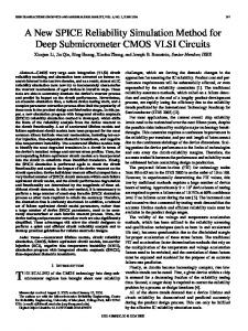
the voltage waveforms for flash cell read, program and erase operations and for address decoding. Its operation is regulated by the commands from a control FSM or from an embedded microcontroller in the flash device itself. The physical layer considered in this work refers to state of the art 2-MLC memories [3], which store two bits per cell by accurately placing four different VT H levels, identified by the statistical distributions L0-L3 shown in Fig. 2. An Erase operation places all the cells within a block on the L0 level (the threshold voltage distribution typically below zero), representing the starting point for each subsequent Program operation which will end up on placing threshold voltages of the selected cells on L1-L3 levels. In order to accurately fulfill the aforementioned operation, a standard algorithm is exploited in NAND Flash memories: the Incremental Step Pulse Programming (ISPP) [14]. A voltage step (whose amplitude and duration are predefined) is applied to the gate of the cells. Afterwards, a Verify operation (i.e. threshold voltage Read) takes place in order to check if the cells VT H have exceeded a predefined voltage value VV F Y (in MLC architectures more than one Verify level is present). If the Verify is successful, the cells have reached the desired distribution level and they are excluded from the following pulses through the so-called Program-inhibition technique [2]. Otherwise, another cycle of ISPP is applied to the cells, where the programming voltage is incremented by ∆ISPP.
L0
L1
R1
VFY1
L2
L3
R2 VFY2
R3 VFY3
OP
Fig. 2. Threshold voltage distributions in a MLC NAND Flash. Read levels (R1, R2, and R3), Verify levels (VFY1, VFY2, VFY3), and overprogramming level (OP) are pointed out. Because of the technological variations, VT H is not perfectly related to the amplitude of the ISPP pulse: there are ”fast” cells which reach the Verify level with few Program pulses, while other ”slow” cells require more pulses. Both kinds of behaviors represent a threat for the reliability of the Program operation, since the threshold voltage distributions of the L1-L3 levels significantly deviate from the ideal gaussian-like shape, thus crossing the distribution read levels (R1-R3) and causing bit errors. Different technological approaches for achieving distribution compactness are commonly pursued, although they share the same underlying principle: acting directly on the ISPP pulse characteristics by decreasing the ∆ISPP per step or by increasing the total number of pulses per Program operation. However, although these methodologies could effectively increase the accuracy of the ISPP algorithm in terms of threshold voltage placement, a substantial penalty both in power consumption and write throughput is paid. An alternative solution for increasing ISPP Programming accuracy with minimal burden on the programming time and complexity has been recently presented in [2], [11]. This algorithm exploits a Double Verify (DV) approach, where the bitline voltage of the selected cells is modulated in order to partially decrease the ∆ISPP step using a prior Verify level with slightly lower voltage than the original Verify level, hence compacting the final desired threshold voltage distribution.
In current flash device controllers, the program algorithm is set at fabrication time and hardwired in memory operation, thus preventing runtime trade-offs. We now illustrate our modeling effort of the highvoltage memory sub-system with the capability to execute both the ISPP-SV (Standard ISPP Single Verify) and ISPPDV (Double Verify ISPP) algorithms. The objective is to capture how different program algorithms impact the raw bit error rate RBER and the power consumption of the memory. 1 We targeted as a case study a 2-bit per cell (4LC) NAND Flash Memory featuring a 45 nm manufacturing process designed for low-power applications. The entire framework has been implemented on a SPICE-like environment using the STM-45nm technology library. The simulation environment is constituted by two distinct modules: the high-voltage (HV) subsystem of the memory, including the charge pumps and the voltage regulators exploited for the generation of the voltages required for the programming algorithm (including the verify stage), and a compact model for NAND Flash memories with array simulation capability. The HV module represents the analog core of a NAND Flash memory. Modifying or reading the number of electrons stored into the floating gate requires a set of bias voltages with a desired precision, timing and granularity. Moreover, many voltages have a value larger than the NAND power supply, requiring the use of several charge pumps. In order to achieve a highly accurate estimation of the power consumption of each ISPP algorithm considered in this work we have simulated the following blocks of the NAND HV subsystem: Program Charge pump, Inhibit Charge pump, Verify Charge pump, Regulators and limiting systems, following the design in [15]. The power consumption of each pump during the various stages of the ISPP algorithms, as measured from the SPICE simulation, is then fed into a NAND Flash power modeling framework based on the equation set provided in [16]. As input parameters of the model, we assumed a low-power NAND Flash supplied with VDD = 1.8V using an ISPP algorithm starting from 14V to 19V and ∆ISPP steps of 250mV. The same settings hold both for the ISPP-SV and the ISPP-DV. Similarly, the HV sub-system functionality simulated in this work is designed to work with both algorithms. In fact, in a NAND Flash device the timing and sequence of analog circuitry operations are driven by the embedded microcontroller/FSM by means of a set of interface registers, generating the enable signals for the charge pumps. Switching from ISPP-SV to ISPP-DV does not require a modification of the HV subsystem but rather implies a different sequence of enable signals notified through the same register interface. An additional modeling effort was devoted to NAND Flash cells. We developed a compact model partially based on [17], which includes variability effects typical of nanoscaled memories. This allowed to simulate array functionalities during a page-wide programming operation. Variability effects included the following: width and length geometrical variations of FG-MOS transistors; nonhomogeneity of tunnel oxide and substrate doping; tunneling caused by the electron injection granularity process into the cells floating gate; Cell-to-Cell interference caused by cross-talk between adjacent floating gates; aging effects due to repeated Program/Erase cycling which typically degrades the RBER. 1
The programming of MLC NAND Flash also depends on the strategy adopted for loading the data to write into the memory. Without loss of generality, we chose to investigate and explore the ISPP full sequence strategy [2] instead of the two-rounds one since it allows reduced simulation time and faster post-processing of the experimental results
All these effects contribute to significantly broaden the gaussian distributions related to the programmed threshold voltage levels within the array, negatively impacting the RBER. For the sake of model validation, we were able to perfectly fit experimental data collected from [17] modeling cell voltage threshold shift during an ISPP transient in 41nm NAND Flash technology.
VI. Experimental results The different sections of the memory sub-system are at first characterized in isolation, and then combined in section VI-C to quantify the trade-offs of the cross-layer approach to memory configuration.
A. Characterization of programming algorithms Power consumption of the NAND Flash device and its RBER when using the ISPP-SV and the ISPP-DV algorithms have been characterized by means of the developed simulation framework. Such parameters are derived as a function of the Program/Erase cycles of the memory, thus enabling lifetime-wide assessment of memory features. Fig. 3 shows RBER results for a simulated 4KB page Program of a NAND Flash. Acting only upon Program algorithm selection to improve memory reliability allows to significantly improve RBER figures up to one order of magnitude. However, this reliability improvement comes with two major penalties: an increase of the power consumption due to the additional verify operations required by the ISPPDV algorithm, and a reduction of the write throughput due to the increased algorithm run time. The increased power consumption of the memory device during a program operation with ISPP-DV instead of ISPP-SV has been measured but not reported for lack of space. Power numbers do not include I/O pins and the digital part, which are irrelevant in the comparative analysis. A shift of just 7.5mW between the two algorithms is measured, which is a marginal 4 to 5% increment with respect to the baseline power with ISPP-SV. Such a consumption mismatch is ascribed mainly to the increased usage of the read charge pump circuitry in the memory HV-subsystem, which anyway does not represent a major source of power drain in the overall consumption context. The power consumption is clearly pattern-dependent. Indeed, programming a page with a target L1 distribution requires less power than a L3 distribution target, as the HV-subsystem of the memory is enabled for a longer time frame. The appealing RBER improvement properties and the minor power cost for that depend on the specific choice of programming algorithms considered in this paper, indicating that ISPP-SV and ISPP-DV are a good choice for future reconfigurable memory sub-systems.
B. ECC characterization Choosing the proper correction capability t of a BCH code is crucial for determining the reliability and the performance of the flash memory. Flash memory based storage systems implementing ECCs are characterized by two values of BER. The RBER is the bit error rate before applying the error correction. The bit error rate after the application of an ECC is usually identified as the UBER. When designing a flash-based system, UBER must fit the acceptable failure rate of the application. It therefore fixes the correction capability the selected ECC must provide.
-2
are reported in Fig.5. We can see that with ISPP-SV the adaptive ECC is reconfigured over time in an attempt to meet the reliability requirement, thus clearly resulting in longer (de-)coding latencies. Since ISPP-DV can contain the RBER with memory aging, ECC requirements can be relaxed accordingly hence almost keeping a constant latency. As will be pointed out in next section, this latency deviations translate into different write and read throughput figures for the two program algorithms.
RBER ISPP-SV RBER ISPP-DV
RBER
10
10
10
-3
1 Order of Magnitude Improvement
-4
160.0 µ
-5 2
3
10
4
10
10
5
10
6
10
Fig. 3. RBER characterization for ISPP-SV and ISPP-DV algorithms. Considering the design of the BCH code, the current trend is to enlarge the block size k over which ECC operations are performed. In fact, longer blocks better handle higher concentrations of errors, providing more protection while using fewer parity bits [21]. For this reason we decided to adopt a block size of k = 4KB equal to the page size of the selected memory, thus overcoming some of the drawbacks of the approach proposed in [19]. Manufacturers usually quote UBER values on their data sheets typically around 10−11 [3]. Given this target, Fig. 4 shows the relation between RBER and UBER achieved by our ECC when using ISPP-SV as program algorithm in the flash device. The specific algorithm determines different RBERs, which even degrade over time, as illustrated in section VI-A. Those RBER ranges then become the x-axis values in Fig. 4.
10
-10
100.0 µ 80.0 µ
40.0 µ
0
1
10
2
10
10
3
4
10
10
5
10
Program/Erase Cycles
Fig. 5. ECC encoding/decoding performance with respect to the chosen ISPP algorithm and memory lifetime. Assumed operating speed is 80 MHz.
C. The new performance-reliability trade-offs The cross-domain approach proposed in this work for performance-reliability trade-off leverages the possibility to act both upon physical and architectural parameters, thus combining their settings into unprecedented combinations. We assume that ISPP-SV and the ECC settings meeting the 10−11 requirement with that algorithm over time are the baseline configurations of the memory sub-system. With respect to that average case, we then ask for improved read throughput or for improved UBER through our crosslayer memory configuration.
-11
t=3 t=4 t = 27 t = 30 t = 65 10
120.0 µ
60.0 µ
-12
1e-6
2.5e-6
5e-6
2.75e-4 3.35e-4
1e-3
RBER
Fig. 4. UBER and RBER relation for ISPP-SV algorithm. The Figure shows that in the best case (left-hand side), tMIN = 3 is sufficient to meet the required reliability constraints. Fig. 4 shows that, in the worst case, the correction capability required by the code is tMAX = 65 errors for the ISPP-SV algorithm. A similar analysis for the ISPP-DV algorithm revealed that a tMAX = 14 is enough for the worst case RBER. We therefore instantiated a BCH codec architecture for the worst case ISPP-SV algorithm with correction capability in the range t = 3 ÷ 65, which is able to accommodate also the relaxed requirements of ISPP-DV and of both program algorithms over time. We then characterized the encoding and decoding latency of this ECC architecture when required to guarantee a constant UBER of 10−11 over time and in the presence of the ISPP-SV and ISPP-DV in the flash device. Results
Write Throughput Loss [%]
UBER
10
ISPP-SV ECC Encoding ISPP-DV ECC Encoding ISPP-SV ECC Decoding ISPP-DV ECC Decoding
140.0 µ
Program/Erase Cycles
Latency [s]
10
48 46 44 42 40 0
10
1
10
2
10
3
10
4
10
5
10
Program/Erase Cycles Fig. 6. Write throughput penalty. 1) Minimizing UBER: Some mission-critical applications may require an UBER value lower than the typical 10−11 one, which was originally projected for the SSD and HDD markets [3]. The improvement of the UBER can be obtained by keeping constant the ECC correction capability, while tuning only on the physical layer. Indeed, by switching from the ISPP-SV algorithm to the more reliable ISPP-DV one it is possible to reduce the overall RBER by an order of magnitude, which directly maps into a reduction of the UBER value.
10
-9
-12
UBER
10
Nominal Physical Layer Modification
-15
10
-18
10
-21
10
0
10
1
10
2
10
3
4
10
10
5
10
Program/Erase Cycles
Read Throughput Gain [%]
Fig. 7. UBER improvement obtained with our approach with respect to nominal NAND Flash operating mode.
the ECC sub-system. Of course, this result is strictly ECC architecture dependent. 3) Trading Write Throughput for Adaptivity: In both adaptivity cases discussed above, when switching away from the baseline memory setting, a loss in write throughput has to be expected for improved read throughput or UBER. In fact, in both cases the program algorithm is switched to ISPP-DV, which takes a longer time to run than the ISPP-SV. Since this time dominates with respect to the encoding latency (1.5ms against the ECC encoder latency which is about two orders of magnitude lower), then the longer program time of the memory can be directly referred to the longer ISPP-DV algorithm. As shown in Fig. 6, the write throughput loss with respect to the baseline setting on average amounts to 40%.
VII. Conclusions
30 25 20 15 10 5 0
0
10
1
10
2
10
3
10
4
10
5
10
In this paper, we demonstrate that combining settings at the physical and architectural level in a memory subsystem holds promise of exposing unprecedented trade-off points between performance and reliability. In particular, read throughput can be improved upon demand at runtime without sacrificing UBER and viceversa. This comes with at a loss in write throughput and with a marginal power penalty in specific use cases. When combining these tradeoffs with those traditionally provided by design techniques for the memory controller architecture, this work paves the way for a more fine-grained optimization of applications and for a higher degree of memory self-adaptivity.
Program/Erase Cycles Fig. 8. Read throughput gain as an effect of the cross-layer optimization. Fig. 7 shows that by exploiting this methodology during the whole memory lifetime, it is possible to achieve an UBER boost which on average amounts to two orders of magnitude but peaks at four orders of magnitude at the end of memory lifetime with respect to the nominal setting. The key benefit of this approach is that the UBER boost does not come at the cost of read throughput penalty, since the decoding time is unaffected. 2) Maximizing Read throughput: Some read intensive scenarios may require the maximum read throughput achievable by the memory, eventually penalizing write throughput performance. By acting only upon the memory controller parameters, the ECC strength would have to be reduced, thus degrading the UBER. In constrast, with a cross-layer approach, it is possible to select the ISPP-DV algorithm, so to provide the best RBER feature during the whole memory lifetime (see Fig. 3), and to concurrently relax the ECC configuration to provide a constant UBER of 10−11 . The decoding latency savings enable to improve the memory read throughput of up to 30% at the end of memory lifetime, as shown in Fig. 8. This depends on two factors. On one hand, read throughput is dominated by decoding latency and not by page read time (which takes up to 75µs against the 150µs of the decoding operation [18]). On the other hand, as previously shown in Fig. 5, the improvement is a strict function of memory aging. The key novelty of this approach lies in the fact that read throughput can be maximized with respect to the average case without impacting UBER. Moreover, the relaxation of ECC performance allows to keep the memory power budget constant since the increased power needs of the physical layer are compensated by the lower power of
References [1] G. Atwood, A. Fazio, D. Mills, and B. Reaves, ”Intel StrataFlash memory technology overview”, Intel Technology Journal, 1997. [2] R. Micheloni, A. Marelli, R. Ravasio, ”Inside NAND Flash Memories”, Springer-Verlag, 2010. [3] N. Mielke, T. Marquart, N. Wu, J. Kessenich, H. Belgal, E. Schares, and F. Trivedi, ”Bit Error Rate in Nand Flash Memories”, In IEEE International Reliability Physics Symposium, 2008. [4] J.-D. Lee, J.-H. Choi, D. Park and K. Kim, ”Data retention characteristics of sub-100 nm NAND flash memory cells”, IEEE Electron Device Letters, vol. 24, no. 12, pp. 748-750, Dec. 2003. [5] R. Bez, E. Camerlenghi, A. Modelli, and A. Visconti, ”Introduction to Flash Memory”, Proceedings of the IEEE, vol. 91, no. 4, pp. 489-502, April 2003. [6] J. Cooke, ”The Inconvenient Truths about NAND Flash Memory”, Micron MEMCON’07 presentation, 2007. [7] R. Dan and R. Singer, White Paper: Implementing MLC NAND Flash for Cost-Effective, High Capacity Memory”, M-Systems, 2003. [8] R. Micheloni et al., ”A 4Gb 2b/cell NAND flash memory with embedded 5b BCH ECC for 36mb/s system read throughput”, in Solid-State Circuits Conference, ISSCC 2006. Digest of Technical Papers. IEEE International, Feb. 2006, pp. 497-506. [9] B. Chen, X. Zhang, and Z. Wang, ”Error correction for multi-level NAND flash memory using ReedSolomon codes,” in Signal Processing Systems, SiPS 2008, Oct. 2008, pp. 94-99. [10] G.G. Marotta et al., ”A 3bit/cell 32Gb NAND flash memory at 34nm with 6MB/s program throughput and with dynamic 2b/cell blocks configuration mode for a program throughput increase up to 13MB/s”, IEEE International Solid-State Circuits Conference Digest of Technical Papers (ISSCC), pp. 444-445, Feb. 2010. [11] C. Miccoli, C. Monzio Compagnoni, A.S. Spinelli, A.L. Lacaita, ”Investigation of the programming accuracy of a double-verify ISPP algorithm for nanoscale NAND Flash memories”, IEEE International Reliability Physics Symposium (IRPS), pp. MY.5.1-MY.5.6, Apr. 2011. [12] C. Zambelli, D. Bertozzi, A. Chimenton and P. Olivo, ”Non Volatile Memory Partitioning Scheme for Technology-based Performance-Reliability Trade-off”, IEEE Embedded System Letters, vol. 3, no. 1, pp. 13-15, 2011. [13] KFG4GH6x4M 4Gb Flex-OneNAND M-die Datasheet, Samsung Electronics, 2008. [14] P. Cappelletti, C. Golla, P. Olivo and E. Zanoni, ”Flash Memories”, Kluwer, 1999. [15] Y.H. Kang, J.-K. Kim, S.W. Hwang, J.Y. Kwak, J.-Y. Park, D. Kim, C.H. Kim, J.Y. Park, Y.-T. Jeong, J.N. Baek, S.C. Jeon, P. Jang, S.H. Lee, Y.-S. Lee, M.-S. Kim, J.-Y. Lee and Y.H. Choi, ”High-Voltage Analog System for a Mobile NAND Flash”, IEEE Journal of Solid-State Circuits, vol. 43, no. 2, pp. 507-517, Feb. 2008. [16] V. Mohan, S. Gurumurthi and M.R. Stan, ”FlashPower: A detailed power model for NAND flash memory”, Design, Automation & Test in Europe Conference & Exhibition (DATE), pp. 502-507, Mar. 2010. [17] A. Spessot, A. Calderoni, P. Fantini, A.S. Spinelli, C.M. Compagnoni, F. Farina, A.L. Lacaita and A. Marmiroli, ”Variability effects on the VT distribution of nanoscale NAND Flash memories”, IEEE International Reliability Physics Symposium (IRPS), pp. 970-974, May 2010. [18] MT29F64G08CBAA[A/B] MLC NAND Flash Datasheet, Micron Technology Inc., 2009. [19] T.-H. Chen, Y.-Y. Hsiao, Y.-T. Hsing, and C.-W. Wu, ”An adaptive-rate error correction scheme for NAND flash memory,” 27th IEEE VLSI Test Symposium (VTS), pp. 53 -58, May 2009. [20] R. Micheloni, A. Marelli, and R. Ravasio, Error Correction Codes for Non-Volatile Memories. Springer Publishing Company, Incorporated, 2008. [21] E. Yaakobi, J. Ma, A. Caulfield, L. Grupp, S. Swanson, P. Siegel, and W. J.K. ”Error correction coding for flash memories,” [Online] http://www.bswd.com/FMS09/FMS09-201-Yaakobi.pdf [22] J. Henkel, L. Bauer, M. Hbner, and A. Grudnitsky. ”i-Core: A run-time adaptive processor for embedded multi-core systems”, International Conference on Engineering of Reconfigurable Systems and Algorithms (ERSA 2011), July 2011. [23] S. Medardoni, M. Lajolo, and D. Bertozzi ”Variation tolerant NoC design by means of self calibrating links”, Design Automation and Test in Europe (DATE), pp. 1402-1407, 2008. [24] Single-Port AHB Nand Flash Controller BA315A Datasheet, www.barco.com/projection systems/downloads/BA315A FS.pdf [25] H. Choi, W. Liu, and W. Sung, ”VLSI implementation of BCH error correction for multilevel cell NAND flash memory” IEEE Transactions on Very Large Scale Integration (VLSI) Systems, vol. 18, no. 6, pp. 843-847, 19-22 Apr. 2010.