The approach will allow the designer to simultaneously edit geometry and composition until a satisfactory result is attained. The concise and machine-general ...
Principal Investigator/Project Director: Institution:
E. M. Sachs, N. M. Patrikalakis, M. J. Cima, W. Cho
Massachusetts Institute of Technology
Award Number:
DMI9617750
Program:
Materials Processing and Manufacturing
Title:
A Design and Post-processing System for Local Composition Control in Solid Freeform Fabrication H. Liu, N. M. Patrikalakis, E. M. Sachs, T. Maekawa, W. Cho and C. C. Stratton Massachusetts Institute of Technology
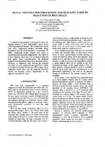
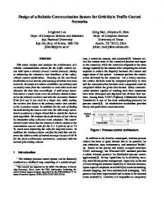
Abstract This article addresses the central impediment to the wide-spread exploration of the potential of Local Composition Control (LCC) in Solid Freeform Fabrication (SFF), and presents a Feature-Based Design (FBD) approach for modeling complex components with LCC. The approach will allow the designer to simultaneously edit geometry and composition until a satisfactory result is attained. The concise and machine-general procedural representation will be maintained throughout the design process and will be evaluated for the purpose of visual feedback to the designer and for post-processing, i.e., the creation of machine-specific instructions for fabrication. 1. INTRODUCTION One of the great potential benefits of the Solid Freeform Fabrication (SFF) technology is the ability to control the internal material composition of components, a capability not shared by conventional mechanical manufacturing processes – see Figure 1 and for more detailed information see also http://www.mit.edu/~tdp/info-flow/. The capability of Local Composition Control (LCC) [2,4] has only begun to be explored by the research teams advancing SFF and exploited by the companies commercializing the technologies. While several compelling applications are under development, it is likely that the potential is largely untapped. Development of methods and tools required to support the representation and design of components with LCC is essential to realize the potential utility of LCC. Most CAD research has focused on the representation of 3D geometry of homogeneous objects, on methods and tools for designers to interact with these representations at a high level, and on derivation of machine specific instructions for machining. Creation of complementary capabilities has not been extensively explored. Several of the current approaches proposed for modeling LCC objects include: (1) Voxel-Based Modeling [7,15]; (2) Finite-Element (FE) Mesh-Based Modeling [17]; and (3) Generalized Modeling Methods such as rm-sets [12,13,14] and generalized cellular decomposition approach [9,10,19]. An analysis of these representation methods can be also found in [11]. Current approaches either based on volume meshing or general decompositions are awkward in editing geometric and material composition information simultaneously, because they lack the concept of editable LCC features; in effect, they permit sequential editing (first of geometry and then composition), which is not flexible and limits the designer's options. Current LCC models are limited to low level data and operators and do not allow for the symbolic representation of the designer's intent with respect to composition. Because of this, design changes cannot be efficiently propagated. Tessellation of the volume of a model (e.g., via tetrahedral meshing) early in the design and fabrication pathway, although expedient for testing of ideas, does not provide a long-term solution for the following reasons: (1)
tessellation implies both approximation of surface geometry and material composition, which is undesirable in general, and for realistic accuracies of approximation leads to verbose evaluated representations that are unattractive for general LCC modelers; (2) tessellation approximation accuracy for surface geometry and material composition can be improved via adaptive meshing procedures, however these are difficult to implement robustly and efficiently; (3) methods for tessellation of a volume into tetrahedral meshes suffer from the general robustness problem in computational geometry relating to inexact computation. In order to overcome these limitations, we propose an approach which builds on the concept of feature-based design (FBD) [6,8,21], which involves the following key concepts: (1) by introducing the concept of editable LCC features, the simultaneous editing of geometric and material information is formalized and simplified; (2) maintenance of an unevaluated exact representation for the geometry and composition for as long as possible along the information pathway provides a high level codification of the design useful in data exchange and in a general setting not associated with a specific SFF process; (3) evaluation of the above exact representation is performed as needed at later stages of the pathway, e.g., for visualization and design verification at an appropriate resolution corresponding to the visualization parameters or for fabrication only at the resolution printable by a particular process.
2. FEATURE BASED DESIGN WITH LOCAL COMPOSITION CONTROL Our feature-based approach for modeling parts with LCC can be characterized as a procedural, unevaluated representation, which becomes evaluated on demand at the resolutions of visualization and fabrication. As such our representation is both compact and exact, avoiding approximations and potentially non-robust geometric algorithms. In comparison with conventional solid modeling, feature-based modeling maintains high level data in the model and relations among them. The high level entities in a feature model provide the user information with engineering significance. Although the current FBD systems carry rich information in terms of features, they only allow users to create multi-material solids with piecewise constant composition using composite structures and assemblies. Due to the nature of FBD, such systems usually cover a limited number of features. In order to address these problems, we propose to extend the definition of features in geometric feature models so as to define the semantics of an LCC feature and extend an existing FBD system to facilitate model creation through LCC features. Identification and formalization of LCC features: The identification and creation of a suite of features for the design of LCC parts is an important component of our work. The basic approach will be to identify potential classes of LCC applications and for each class, identify features, which would be useful in design. For the purpose of allowing users to specify composition variation in the interior of a solid, we define an LCC feature as a construct with two attributes: (1) a generic parametrizable shape and (2) a composition function defined over the shape. In terms of data structure, an LCC feature is composed of two substructures, one providing the representation of generic shape, the other providing the representation of composition profile. Therefore, the LCC feature can be viewed as primarily comprising two sub-features, respectively for geometric shape and composition profile. The geometric sub-feature can be any standard geometric feature or its extension by general user-defined feature (UDF) [8] method, i.e., volume features, transition features, pattern features and user-defined features. Composition profile sub-feature has parameters such as material subspace and constraints on material composition. It also possesses attributes defined through composition functions. Composition is the vector of volume fractions of each material defined over the material subspace and the generic shape of the feature. Composition function is the mapping function from the geometric sub-feature to the material subspace. Composition constraints (design rules) are typically inequalities that specify e.g., what material composition or what gradient of material composition can be fabricated. Development of classes of LCC features: Using feature-based parametric design methods, we developed tools for LCC composition function design and editing of LCC features via extending a current feature-based design system. Firstly, composition function can be constructed as analytic function of distance(s) from an interior point of the solid to a geometric feature or reference geometric feature. When multiple composition profiles are applied, composition function is the weighted sum of the relevant profiles. Composition function(s) are constrained to a volume that is represented with a graph of geometric features so that an LCC feature is constructed. Because composition functions are parametrized with respect to geometric features instead of geometric entities, the composition functions can be edited simultaneously with the geometry. Secondly, composition function can also be a pattern mapped from a composition feature that is constrained on a seed component in a pattern feature. Finally, composition function that is a blending function governed by the Laplace equation is developed. In this case the blending function is applied to a
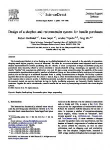
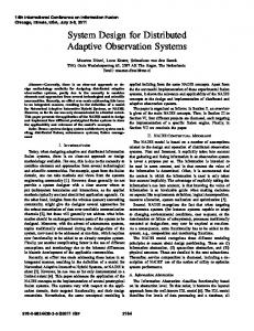
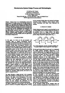
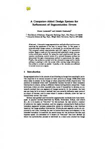
component whose adjacent components have been assigned some composition features. Using the parametrized splitting with constrained surfaces to cut a component into adjacent sub-components, a smooth gradient of composition within a part according to user-defined parameters can be achieved. The same method can be also used to develop blending with other functions such as Poisson equation. In the case of pattern composition and blending composition features, LCC assembly features are constructed in stead. Development of generic feature-based representation of LCC objects: We propose a feature-based LCC object modeling approach based on an existing feature-based modeling system. As demonstrated in Figure 2, feature data in such a model are structured into five levels: an assembly model, an LCC feature model, a part (component) model, a feature model and a generic model. The assembly model is the model at the highest level. Hatched arrows in Figure 2 represent the mapping of elements of higher level model to that of lower level models. Efficient and robust evaluation of LCC object at different levels of resolution for both visualization and fabrication: Evaluation of LCC object for visualization and SFF fabrication is an important part of the work. Considering different types of rendering methods and different required resolutions, appropriate intermediate models will be constructed. For example, issues related to 3DP process will be taken into account to accommodate the downstream processing, i.e., machine instruction generation. Efficiency and robustness are very important requirements for the evaluation of LCC object especially when there are a large number of queries to make for the intermediate model and large number of features in the LCC object or the composition profile is very complicated. Composition evaluation algorithms could be customized for different types of LCC features. For example, given an LCC model, where the composition is defined as a function of the minimum distance to the boundary of the model, efficient Euclidean digital distance transform algorithm [20] could be used to approximate the minimum distance at the voxel level. Implementation: A prototype local composition control modeler has been developed. It allows users to design LCC solids using several types of features including LCC volumetric feature, LCC surface feature, LCC pattern feature and LCC fillet feature. Efficient evaluation methods for the above features are developed. The class of composition features that represents material composition as a function of minimum distance to the user-defined or user-specified features is developed. Efficient distance computation methods are developed based on preprocessing the geometry features of the solid and the digital distance transform algorithm. Composition functions are also derived for pattern and fillet features. Blending composition functions governed by the Laplace partial differential equation are also developed. The Laplace equation is solved with 3D Boundary Element method [1]. Simultaneous editing of both geometry and composition feature is achieved. As an example, Figure 3 demonstrates a tooling part that is made of two materials and designed such that the material composition around the cooling channel is a function of the minimum distance to that cooling channel. Similarly, other parts for which composition around surface features needs to be modified in terms of distance to the surface features can be designed. For example, compositions can be designed as demonstrated in Figure 4 such that different composition profiles are applied to different surface features. When the different profiles interfere with each other, compositions are blended proportionately. As a special usage of this class of LCC feature, user can define the composition ratio as a function of the minimum distance to the part boundary that is composed of a sequence of features as demonstrated in Figure 5. An illustration of LCC pattern feature is shown in Figure 8, where the composition pattern is a circular mapping of that of the seed component. An example of material fillet using the blending function governed by the Laplace equation is given in Figure 7. Efficient evaluation of these classes of LCC feature is also developed at required resolutions. Applications: Gradient index lenses: Gradient index lenses refract light by gradients in the index of refraction, rather than by external geometry. Such lenses can provide the functionality normally associated with multi-component ground optics at lower cost and in a smaller space. A cylindrical gradient index lens with composition gradient can be created by extrusion of a 2D closed circle, while the composition function is parametrized with respect to the local cylindrical coordinates as shown in Figure 6. In this application, composition features that represent analytical functions of user defined cylindrical coordinates need to be developed. The analytical functions can also be B-spline interpolations of user input. Design rules are to be introduced at the specifics of the GRIN lens, which are represented as mathematical inequalities. For the case where the composition is only a function of radius, a higher level tool will be developed so that the user can specify the lens in terms of its focal length. Assuming the focal length is large in relation to the lens height, ray tracing methods will be utilized to derive the required local index of refraction as a
function of the radial coordinate in order to achieve a specific focal length. In this way, a high level functional specification of a part will become possible for the first time in this context. Parts with wear resistant surfaces: Parts with wear resistant surfaces can be made via 3DP LCC. Hard phases such as TiC can be printed near the surface of a tool for increased wear resistance. A specific feature will be developed that represents composition variation from a selected portion of the boundary toward the interior. The composition function is either an analytical or a B-spline interpolated function of the minimum distance to the target surface. Efficient methods for the evaluation of composition at different resolutions based on spatial subdivision and digital distance transform techniques will be developed for this purpose. 3. POST-PROCESSING Our FBD approach for modeling solids with LCC is generic and applicable to a broad range of SFF technologies. However, in the cases where the outcome is process specific, Three-Dimensional Printing (3D Printing) [18] (see also Figure 1) is used as the prototypical SFF technology. 3D Printing has made it possible to print continuously varying multi-material composition by the simultaneous use of multiple printheads. Each printhead dispenses a fluid which may serve to physically bind the part together, act as dopant to modify the material properties, or both. Postprocessing is required to convert the LCC model created by the FBD process into machine instructions for its realization via 3D Printing. In this context, there are two major issues: (1) an intermediate representation scheme should be provided which converts the continuous-tone composition variation into printable, discrete information throughout the volume of an LCC object, to serve as link between design and fabrication stages; (2) as a result of such conversion, the transformed boundary may only approximate the boundary of the LCC object and accordingly, it would lead to difficulty for the precise specification of geometry and composition near the boundary. A solution to the former issue would be a conversion of the LCC feature model into a voxelized representation, where we note each voxel will correspond to our 3D dither cell [5]. A 3D dither cell consists of n f × n s × n v bi-level subvoxels for each material in fast, slow, and vertical axis of the 3D printing device, where fast (slow) axis denotes high (slow) speed raster-scan direction of the machine, respectively, and the vertical axis denotes the direction normal to the layer plane. A set of those 3D dither cells will optimally simulate continuous-tone graded composition of the LCC model in a point-wise fashion as detailed in [5]. The size of a 3D dither cell is chosen as a compromise between the resolution and the storage cost of the intermediate voxelized representation. We also note that our dithering approach is generic in terms of LCC modeling/fabrication methods, and can be applied to various kinds of LCC modelers/point-wise fabrication processes. To increase the resolution of the bi-level half-toning printing, we have developed a three-level half-toning printing technique building upon the method of [16] by adding 50 % dilute dopant as a printing option. The introduction of three-level half-toning doubles the composition resolution achievable in bi-level half-toning without having to lose the geometric resolution. The bi-level half-toning creates the illusion of continuous-tone images from judicious arrangement of binary picture elements (PELs) [5]. If the PEL is turned “on”, the 100% dopant will be printed to the PEL, while if it is “off” no dopant will be printed. In the three-level half-toning printing, we have one more option, namely the 50% dilute dopant. We apply the bi-level half-toning to dither cells having compositions between 0% and 50 % with respect to this range. For turned “on” PELs, 50% dilute dopant will be printed, while no dopant will be provided for turned “off” PELs. If the composition of the dither cell is between 50% and 100%, we similarly apply the bi-level half-toning with respect to this range. The 100% dopant will be printed onto PELs that are turned “on”, while the 50% dilute dopant will be printed onto the turned “off” PELs. 3D printing can utilize two different methods to increase the fidelity of sharply defined geometric or composition boundaries. One method utilizes a continuous-jet printhead with a capability of proportional deflection [18]. In proportionally deflected printing, droplets can be steered to any position within the maximum deflection range in the slow-axis direction. The use of proportional deflection offers significant potential to improve the quality of the printed parts with no compromise in production rate. The other approach is to utilize a drop-on-demand (DoD) printhead moved in a vector path along the boundary being printed. Vector DoD printing yields the highest part quality, but takes more time than approximating the boundary while raster-printing the interior. With either method of boundary printing, the droplet density may be modulated to vary the local composition. To achieve an accurate composition/geometry near the boundary, an algorithm is required which identifies the necessary boundary droplets to be printed. The algorithm should ensure that the total concentration Cb of the sum of all dispensed fluids having
binding properties satisfies a required amount Cτ at the boundary sufficient to guarantee structural integrity. Such required amount will vary from system to system, however, would typically be between 10% - 50% of full saturation. At present [3,5], Cτ is forced to be 100%. A general scheme is under development, which guarantees sufficient binding at the surface to satisfy the geometric design intent with the minimum possible deviation from the composition design intent. 4. CONCLUSION The major barrier to the wide-spread exploration of the potential of LCC in SFF is due to the lack of electronic representations and design tools for objects with LCC. Most CAD research has focused on the representation of 3D geometry of homogeneous objects, on methods and tools for designers to interact with these representations at a high level, and on derivation of machine specific instructions for machining. Current approaches proposed for modeling LCC objects are awkward in editing geometric and material composition information simultaneously. In effect, they permit sequential editing (i.e., first of geometry and then composition), which is not flexible and limits the designer's options. Current LCC models are also limited to low level data and operators and do not allow for the symbolic representation of the designer's intent with respect to composition. Also as such, design changes cannot be efficiently propagated. In order to address these limitations, our proposed approach builds on the concept of feature-based design (FBD) and extends it from a geometric domain to simultaneous material and geometric editing of features. Key issues involved in our FBD approach to LCC modeling include: identification and formalization of LCC features; development of LCC feature creation and editing techniques; a generic feature-based representation of LCC objects; and their efficient and robust evaluation at different levels of resolution for both visualization and fabrication purposes. An unevaluated exact representation for the geometry and composition is maintained for as long as possible along the information pathway, which provides a high level codification of the design useful in data exchange and in a general setting not associated with a specific SFF process. Evaluation of the exact representation is performed as needed at later stages of the pathway, e.g., for visualization and design verification at an appropriate resolution corresponding to the visualization parameters or for fabrication only at the resolution printable by a particular process. Conversion of an LCC model created by the FBD process into machine instructions is performed via post-processing for its realization via 3D Printing. A voxelized representation relying on the optimal volume dithering is used to serve as an intermediate representation scheme which converts the continuous-tone composition variation into printable, discrete information throughout the volume of an LCC object. As a result of such conversion, the transformed boundary may only approximate the boundary of the LCC object. To achieve an accurate composition/geometry near the boundary, a general scheme will be developed, which guarantees sufficient binding at the surface to satisfy the geometric design intent with the minimum possible deviation from the composition design intent. ACKNOWLEDGMENT NSF under grants DMI-9617750, DMI-0100194. REFERENCES [1] C. A. Brebbia, J.C.F. Telles and L.C. Wrobel. Boundary Element Techniques, Theory and Applications in Engineering. Springer-Verlag. 1984. [2] W. Cho, E. M. Sachs, and N. M. Patrikalakis. Solid Freeform Fabrication with Local Composition Control. Invited paper in Rapid Prototyping, Quarterly of the Rapid Prototyping Association of the Society of Manufacturing Engineers. 7(2):1-5, Second Quarter Issue, 2001. Dearborn, MI: SME. [3] W. Cho, E. M. Sachs, N. M. Patrikalakis, M. J. Cima, T. R. Jackson, H. Liu, J. Serdy, C. C. Stratton, H. Wu, and R. Resnick. Methods for distributed design and fabrication of parts with local composition control, Proceedings of the 2001 NSF Design and Manufacturing Grantees Conference, Tampa, FL, USA, January 2001.
[4] W. Cho, E. M. Sachs, N. M. Patrikalakis, M. Cima, H. Liu, J. Serdy, C. C. Stratton. Local composition control in solid freeform fabrication. Proceedings of the 2002 NSF Design, Service and Manufacturing Grantees and Research Conference, San Juan, Puerto Rico, January 2002. [5] W. Cho, E. M. Sachs, N. M. Patrikalakis and D. E. Troxel. A dithering algorithm for Local Composition Control with Three-Dimensional Printing, Computer Aided Design, in press. (available in Publication section of http://www.mit.edu/~tdp/info-flow/) [6] R. Bidarra and W. F. Bronsvoort. Semantic feature modeling, Computer-Aided Design, 32(3):201-225, March 2000. [7] V. Chandru, S. Manohar, and C. E. Prakash. Voxel-based modeling for layered manufacturing. IEEE Computer Graphics and Applications, 15(6):42-47, November 1995. [8] C. M. Hoffmann and R. Joan-Arinyo. On user-defined features. Computer-Aided Design, 30(5):321-332, April 1998. [9] T. R. Jackson, H. Liu, N. M. Patrikalakis, E. M. Sachs, and M. J. Cima. Modeling and designing functionally graded material components for fabrication with local composition control. Materials and Design, 20(2/3):63-75, June 1999. [10] T. R. Jackson, N. M. Patrikalakis, E. M. Sachs, and M. J. Cima. Modeling and designing components with locally controlled composition. In D. L. Bourell et al, editor, Solid Freeform Fabrication Symposium, pages 259-266, Austin, Texas, August 10-12 1998. The University of Texas. [11] T. R. Jackson. Analysis of Functionally Graded Material Object Representation Methods, PhD Thesis, MIT, January 2000. [12] V. Kumar, D. Burns, D. Dutta, and C. Hoffmann. A framework for object modeling. Computer-Aided Design, 31(9):541--556, August 1999. [13] V. Kumar and D. Dutta. An approach to modeling and representation of heterogeneous objects. Journal of Mechanical Design, 120:659--667, December 1998. [14] V. Kumar and D. Dutta. An approach to modeling multi-material objects. In C. Hoffmann and W. Bronsvort, editors, Fourth Symposium on Solid Modeling and Applications, Atlanta, Georgia, May 14-16, 1997, pages 336--353, New York, 1997. ACM SIGGRAPH. [15] S. Manohar. Advances in volume graphics, Computers and Graphics, 23(9):73-84, 1999. [16] V. Ostromoukhov, P. Emmel, N.Rudaz, I. Amidror, R. D. Herch. Multi-level colour halftoning algorithms. International Symposium on Advanced Imaging and Network Technologies. Berlin, October 1996, SPIE Vol 2949:332340 [17] J. Pegna and A. Safi. CAD modeling of multi-modal structures for free-form fabrication, 1998. In D. L. Bourell et al, editor, Solid Freeform Fabrication Symposium, Austin, Texas, August, 1998. The University of Texas. [18] E. M. Sachs, D. Brancazio, J. Milner, J. Serdy, A. Curodeau, and J. Bredt. High rate, high quality 3D printing through machine design, on-line measurement, and control, International Journal of Machine Tools and Manufacturing, to appear. [19] E. M. Sachs, N. M. Patrikalakis, D. Boning, M. J. Cima, T. R. Jackson, and R. Resnick. The distributed design and fabrication of metal parts and tooling by 3D Printing. In Proceedings of the 1998 NSF Design and Manufacturing Grantees Conference, Cintermex Conference Center, Monterrey, Mexico, pages 35--36. Arlington, VA: NSF, January 1998.
[20] T. Saito and J. Toriwaki. New algorithms for Euclidean distance transformation of an n-dimensional digitized picture with applications, Pattern Recognition, 27(11):1551--1565, 1994. [21] J. Shah and M. Mantyla. Parametric and Feature-Based CAD/CAM, John Wiley, Inc., 1995.
FIGURES
Figure 1: Illustration of Local Composition Control via 3D Printing
Figure 2: LCC object modeler
Figure 3: Implementation: a tooling part – composition around surface feature
Figure 4: Implementation: a tooling part – different composition profiles around different surface features
Figure 5: Implementation: a tooling part – composition ratio as a function of distance to boundary
Figure 6: Volume LCC fillet with the composition blended using the Laplace equation
Figure 7: GRIN lens with composition as a function of (r,h,φ)
Figure 8 Applications (from left to right): Scaffold for tissue engineering; Drug delivery device; Gradient index lenses