For example, in crack detection, the black sad- ... regions are extracted via a white top-hat operation ... Go(x) be a input image , a conditional histogram.
MVA2000 IAPR Workshop on Machine Vision Applications. Nov. 28-30.2000, The University of Tokyo, Japan
8-35 A Detection Method of Cracks and Structural Objects of the Road Surface Image N a o l Tanaka * Chair of Information Systems Eng. Kobe University of Mercantile Marine Masayo MOURI Graduate School of Maritime Science and Technology Kobe University of Mercantile Marine
Abstract This paper introduces a new detection method of crack and structural objects, whiteline , joint and manhole of the road surface image based on morphological t,echnique . Crack and structural objects are difficult to detect directly at the pixel level because of the noise and the vagueness. Some kind of structural information is needed. In the proposed method, we have used morphologcal operations which are able to extract specify shapes explicitly Although the method requires the setting of some parameters, it is robust for detecting vague crack and st(ructura1objects in the noisy road surface image.
.
1
Notation
2 2.1
Mathematical morphology includes four basic o p erations: dilation, erosion, opening and closing. We make use of these four kind of operations and conditional dilation and t o p h a t operation throughout this work . The four basic operations are also distinguished into binary operations and gray scale o p erations, they are denoted as follows: Dilation(@,a,), erosion(^, e,),Opening(0, 0,) and Closing(., a,). Conditional dilation is denoted as follows: (Go(x) [ @ I ) .
2.2
Introduction
In the maintenance of the road , the detection of crack [I]and structural objects on the road surface, i.e. white lines (center line ) ,joint and manhole is one of the major problems. Such objects may be easily recognized by the human visual systems, but are difficult to segment [2]. This difficulty arises from the fact that they cannot be detected directly at the pixel level because of the noise and the vagueness. Some kind of structural information is also needed. We have used morphological operations [3] [4] here to extract specific shapes from the road surface image. For example, in crack detection, the black saddle points are detected via a black tophat operation [5] with a tiny disk-shaped structure element and in the whiteline detection , the large white rectangle regions are extracted via a white top-hat operation with a long line- shaped structure element. An advantage of the proposed method is its robustness against noise and vagueness of the objects. --
'Address: 5 1 - 1 , fukae-minami, higashinada, Kobe 6580022, Japan. Email: tanakaoathena. ti .kshosen.ac. j p ~ d d r e s s : 5 1-1, fukae-minami, higashinada, Kobe 6580022, Japan. Email: mouriQti.kshosen. ac j p
.
Morphological Operation
Structure Element
Three kinds of standard shaped stxucture element, i.e. DISK , LINE and SQUARE are selected in our studying. They are described as following: A DISK-shaped structure element with its origin at the center and radius i is denoted by K d i s k (i). A LINEshaped structure element with length 1 and direction 8 is denoted by Kli,,e(l). A SQUAREshaped structure element with length of e is denoted by K ,,,,,, (e).
3
Crack Detection
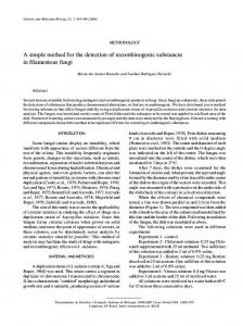
The crack detection process falls into four stages: 1) black pixel extraction ; 2)saddle point extraction ; 3) noise reduction; 4)connecting processing. Let Go(x) be a input image , a conditional histogram equalization is adopted in order to improve the contrast of a darker image. H (x) =
HT(G,(x))
: Ave(H(x)) 5 100
: Ave(H(x)) > 100
Figure 1: H ( x )
Figure 3: Tc(x)
Figure 2: B c ( x )
Figure 4: Mc2(x)
where H T ( ) denotes a histogram equalization. An example of histogram equalized image H ( x ) is shown in Fig. 1.
3.1
By taking an intersection of Bc(x) and T c ( x ) , Mc(x) can be obtained.
Black Region Extraction
M c ( x ) = B c ( x )n Tc(x)
Since a crack is constituted by black pixels, black pixel regions are extracted in this stage . To evaluate the relative blackness of the regions , we use the average value Ave and the standard deviation Sd of the whole image and local average values ave(x) and local standard deviations s d ( x ) in a window.
B c ( x )=
Eliminating the small regions in Mc(x) , we can obtain Mc2(x) . An example of Mc2(x) are shown in Fig. 4.
3.4
Connecting Processing
Connecting process is starting with the image 1 : ( ( H ( x )< (Ave - Sd) and Mc(x) and Mc2( x ) . To fill gaps of Mc(x) , a dilation ( H ( x )< (ave(x)- s d ( x ) )and ( s d ( x )> 20)) and a conditional dilation are carried out. 0 : ( ( H ( x )2 (Ave - Sd) or ( H ( x )2 (ave(x)- s d ( x ) )or ( s d ( x ) 5 20)) M c 3 ( ~= ) M c ( x )@ Kdisk(3)
At this stage, a few large regions and/or a number of small regions are expected to be extracted as crack regions. So , B c ( x ) which includes only a few small regions can be abandoned here. An example of B c ( x ) are shown in Fig. 2.
3.2
3*3
Saddle point extraction
The saddle point extraction stage is defined as follows.
T c ( x )= IHTnz(H(x)Og Kdisk(20) - H(x))lO,
-
where HTn, () denot,es a histogram equalization against none zero gray levels , and O1 = 230 255 which is depend on a value A v e ( H T ( H ( x ) og Kdiek(20)- H ( x ) ) ). An example of Tc(x)are shown in Fig. 3.
M c ~ ( x=) M c ~ ( x/ )~
M ~ ~@ (Ksquare(3) z )
Finally the resulting image Mmack(x)can be obtained by eliminating small regions of M c l ( x ) . An example of desired image and Mcrack(x) are shown in Fig. 5 and Fig. 6 respectively.
---
,.
1
Figure 5: Desired image(crack)
4
Figure 6: MCTack
Figure 9: Twhite
Figure 7: Go(x)(whiteline)
Figure 10: G,(x)(joint)
White Line Detection
Because of the roughness of a road surface , there appear many small gaps and/or holes in whiteline regions of t,he input image. Therefore a morphological smoot,hing operation are carried out in order to fill t,he gaps and t,he holes.
A whiteline is composed of white , i.e. bright rectangle region , so it can be extracted from a white top-hat operation .
, vertical
where O2 = 50. Eliminating the small regions of Tw( x ) , Twh,te( x ) can be obtained. Examples of G o ( x ), desired image and Twhite(x)are shown in Fig. 7 , Fig. 8 and Fig. 9 respectively.
flat regions. Canny edge detecting operat,or is used here to extract such regions.
A joint region is broad enough to contacts to at least two image ends and wider than a quarter of the horizontal dimension of the image . Eliminating regions which are not satisfied both of these two conditions from C j( x ) , we can obtain E j ( x ) . Final detecting result of joint is obtained after a dilation operation.
Examples of G,(x) , desired image and Djoint(x) are shown in Fig. 10 , Fig. 11 and Fig. 12 respectively.
6
Manhole Detection
Since a joint is made of a kind of metal , it has smooth surface and can be detected by extracting
A manhole is a disk with rugged surface. A manhole has round shape , so we first extract round shape components. We use a black top-hat operation with disk shape structure element to extract that components.
Figure 8: Desired image(white line)
Figure 11: Desired image(joint)
5
Joint Detection
Figure 12: Djoint
Figure 15: Mmanhole
Table 1: The experimental results of crack and structural objects detection.
Figure 13: Go(x)(manhole)
where O3 = 120. Because a manhole is composed of black regions , a masking operation is made on T,(x) with the thresholded input image.
where e4 = 40. Eliminating the too small regions as a component of manhole from A, (x), then also eliminate the regions which include no hole. This is because the ruggedness of the surface makes some holes in the monhole components .Now we can obtain a result image Mmanhole(x). Examples of Go(x) , desired image and Mmanhole(x) are shown in Fig. 13 , Fig. 14 and Fig. 15 respectively.
7
Experimental Results
We have 319 of road surface images as the test images ,which are attached the interpretation results of the images via a expert. There exists 105 of crack images , 44 of whiteline images ,9 of joint images and 6 of monhole images among them. Each image
Figure 14: Desired image(manho1e)
is processed by the four kind of detection processes simultaneously. The experimantal results are shown in table 1.
8
Conclusion
A morphological method to detect crack ,whiteline,joint and manhole of the road surface image is proposed in this paper. Although the proposed method requires the setting of some parameters, it is robust and high performance for detecting vague objects in the noisy road surface image.
References [I] N. Tanaka,K. Uematsu, "A Crack Detection Method in Road Surface Images Using Morphology" , IAPR Workshop on Machine Vision Applications '98, Nov. 1998, pp.154-157. [2] H. Talbot, "A Morphological Algorithm for Linear Segment Detection" , Mathematical Morphology and its Applications to Image and Signal Processing, Kluwer Academic Pub. 1996. [3] R.M. Haralick,S.R.Sternberg,and Zhang, "Image analysis using mathematical morphology", IEEE Trans , PAM1 , Vo1.9, No.4 , July 1987 , pp.532-550. (41 R.M. Haralick,"Computer and Robot Vision" , Addison Wesley , 1992. [5] J . Serra, "A nalysis and Mathematical Morphology" ,Academic Press ,1982.