Detection and quantification of surface cracks by X-ray micro-computed tomography Amin Garbout1,Karl Ritz2, Craig Sturrock2, Sacha Mooney2 , Elena Armenise3, Sujung Ahn4, Robert Simmons3, Stefan Doerr4 1 Imaging
and Analysis Centre (IAC), The Natural History Museum, U.K 2 Division of Agriculture & Environmental Sciences, School of Biosciences, University of Nottingham, U.K 3 School Of Applied Sciences, Cranfield University, U.K 4 College of Science, Swansea University, UK Corresponding author:
[email protected]
Introduction The surface of a material, as characterised by its topology and roughness, has a profound effect on its functional behaviour. Its structural integrity may be degraded by the stable growth of cracks formed from small defects under the influence of stress and/or the environment. Cracks formed at the surface are critical as they reduce the performance of a material, including mechanical properties and integrity, as well as transport/barrier properties in general. In soils, cracks resulting from desiccation modify a material’s mechanical and hydraulic properties.
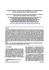
Desiccation
Desiccation + +
Tensile stress developing in upper layer: drying process results in development of capillary suction with new arrangement of soil particles
Surface crack initiated: tensile stress increase as evaporation proceeds
Soil surface crack: 2D view of a CT image of a crack formed in soil.
Fig.1 : Illustration of soil crack formation processes
Materials and methods • A new method was developed, based on the use of X-ray micro-computed tomography (CT) (Fig.2-a)., which enables non-invasive and non-destructive 3D quantification of material structure at high resolution (65 µm). • An adaptive algorithm was developed to automatically capture the soil surface in 3D and 2D (Fig.2-b). • Surface cracks formed in dry soil were differentiated from other pores by their pattern, size, and directionality (Fig.3-a and Table 1).
B
A 2D Soil surface
C
Pore space
Soil surface
Soil matrix
3D view of soil surface Fig.2-a : CT scanning of a soil sample: Investigation of the surface cracks formed.
A
Fig.2-b : Detection of the soil surface: The pore space can be visualised at different depths below the soil surface (see A-C).
B Soil 1
Soil 1
Soil 2
Soil 2
Colour
Volume (mm³)
Surface Area (mm²)
Thickness (mm)
Max Thickness (mm)
1
pink
465
955
1.6
2.5
2
orange
86
215
1.4
2.0
3
white
1985
4262
1.5
2.7
Crack number Soil 3
Soil 3
Fig.3-a: 3D images of the top surface of a dry soil: Surface crack thickness (A) with calibration bar in mm, and 3D view of 3 different cracks (B).
Table 1: Different cracks detected at soil surface and quantification of their pattern. 600 500
Results and Discussion • The volume of the three cracks decrease with depth (Fig.4). • Crack 3 has a thickness of 1.5mm, with a depth of up to 21mm. • Crack 1 is 15mm in depth, but with a thickness of 1.6mm. • We do not observe a correlation between crack width and depth • The mean thickness does not inform our understanding of the severity of a crack. • Crack penetration is related to volume and surface area.
Crack volume (in mm3)
400
1
300
2 200
3
100 0 -100
0-3
6-9
15-18 Crack depth (in mm)
Fig.4: Volume of 3 different crack formed at soil surface within depth
Conclusions • • • •
Crack number
Micro-CT shows great potential for characterisation of surface cracks. The developed adaptive algorithm is well suited for the detection of cracks at the surface. It is important to characterise surface cracks, so as to be able to determine their size, and effect on the breaking stress of a structure. Additional parameters are required to adequately describe crack morphology, such as their orientation or anisotropy. This work was partly supported by the UK Biotechnology Research Council Grant number BB/J006092/1 and a Jonathan Ruffer Curatorial Research Grant from the Art Fund