Jul 2, 2004 - tuning method of PID controller parameters is still a hot research area. ... parameten. Computer simulations are performed for an example of ...
Proceeding of the 2004 American Control Conference Boston, Massachusetts June 30 -July 2,2004
I
WeM14.6
A Developed Method of Tuning PID Controllers with Fuzzy Rules for Integrating Processes Jianming Zhang, Ning Wang and Shuqing Wang
AbstmcG The proportional integral derivative (PID) controllers are widely applied in industrial process, and the tuning method of PID controller parameters is still a hot research area. A fuzzy tuning scheme for PID controller settings is developed for integrator plus time delay processes in this paper, in which a fuzzy rule base reasoning method are utilized on-line to determine a tuning parameter a based on the error and the first change of the error of the process. Then this tuning parameter a is used to calculate the PID controller parameten. Computer simulations are performed for an example of integrating plants. Comparing to some reported methods, the performance of the presented approach is shown to be satisfying.
I. INTRODUCTION
1.
N industrial process control area,the proportional-integral-
. '
derivative (PID) controllers are still widely used because of their simple structure, easy understanding to operators, robust performance in a wide range of operating conditions, and their easy implementation using analogue or digital hardware. It has been reported that more than 95% of the controllers in industrial process control applications are of the PID type controller [2]. Integrating processes are frequently encountered in the process industries. Many chemical processes can be modeled by a pure integrator plus time delay model such as kexp(-m)/s . Since the model contains only two parameters (the proportional coefficient k and the time delay constant T ), it is very convenient for estimating the model parameters by relay feedback method or closed-loop identification [3],[4]. Recent years, more and more PID tuning methods are proposed to deal with various integrating processes. Chien
and Fruehauf [SI proposed an internal model control (IMC) method to find the settings for a PI controller, in a process consisting of an infegrator and a time delay. Tyreus and Luyben [6] pointed out that the IMC-based PI controller could lead to a poor'control performance unless care i s taken in selecting the closed-loop time constant, and proposed an alternative approach based on classical frequency response methods for PI settings. This tuning rule has been extended to design PID controllers by Luyben in [7]. Wang and Cluett [8] also discussed this control problem and proposed a PID controller designing method based on specification in terms of desired control on signal trajectory which is scaled with respect to the magnitude of the coefficient in the second term of the Taylor's series expansion. More recently, Visioli [9] proposed a tuning method for integrating systems based on minimizing ISE, ISTE and ITSE with a genetic algorithm. The results are fitted by simple equations related to the proportional coefficient k and the time delay constant T of the process. However, the optimization for servo response results in a PD cotdoller and only the results for regulatory response can give a PID controller. Chidambaram and Sree [I] proposed a simple method for the PI, PD and PID controller settings for such process based on matching the coefficients of corresponding powers of s in the numerator and that in the denominator of the closed-loop transfer function. Since there is only one adjustable parameter a for the PID tuner, care must be taken in selecting the tuning parameter a in order to obtaining a good performance. In this paper, a fuzzy inference method is introduced to find a proper value a according to the response ofthe closed loop system. The perfom;ance of the modified method is shown with an example. The paper is organized as following. The next section gives a brief introdhction of the method proposed in [I]. Section I l l presents the tuning rules with fuzzy inference for the tuning parameter a .Computer simulations and results are given in section IV, and the performance of the proposed method is compared with that of [I], [7]-[9]. Conclusions are summarized in Sectionv' ~~
Manuscript received Seplember 20,2003. Jianming Zhang is the National Key Laboratory of contra^ Technology, institute of Advanced process control, Zhejiang University, Hanpzhou, 310027, P. R. ofChina. (Phone: 086-571-87951 125; Fax: 086571-87951445; email: jmzhanga iipc.zju.edu.cn). Nine Wanr! is with the National Kev Laboratow of Industrial Control Technology, Institute of Advanced Process Control, Zhejiang Universiv, Hangzhou, 310027. (e-mail: "wan@ iip.zju edu.cn). Shuqing Wang is with the National Key Laboratory oflndushial Control Technology, Instirule of Advanced procUs cantroi, Zhejiang university, Hangzhhou, 310027. (e-mail: rqwang@ iipc.zju.edu.cn).
-
-
0-7803-83354/04/$17.00 02004 AACC
~~~~~~~
11. PREVIOUS TUNING METHOD FOR PID CONTROLLERS
Chidambaram and Sree U1 proposed a simple method for
1109
the PI, PD and PID controller settings based on matching the coefficients of corresponding powers of s in the numerator and that in the denominator of the closed-loop transfer function for a servo problem. Their method is described briefly as follows [I]. For an integrator plus time delay process represented by transfer function kexp(-rs)/s , considering the following PID type controller, G, = k, l + - + T d s
[Tfs the proportional gain of PID controller,
1r.
. Where, k, and
is
rd are
known as the integral and derivative time constants, respectively. The closed-loop transfer function can be given by ~y ( q ) - (Klq+ K, +K,q2)exp(-q) (1) Y , ( q ) q2 + ( K l q + K, + K3q2)exp(-q) ’ where, s is the Laplace operator, K T K , = k , k r , K2=-, K3=KIA,q=sr. (2) Ti I. r Approximating the time delay term in the denominator by a first-order pade approximation, 1 - 0.5q exp(-q) ~i ~. (3) 1+ 0.5q The resulting equation can be written as y ( q ) = (K,q+K2 +K,q2)(1+0.5q)exp(-q) , (4) Y , ( q ) q2(1+0.5q)+ (Klq+ K 2 + K3q2)(1- OSq) Removing exp(-q) in the numerator and introducing a parameter a as the coefficients of corresponding powers o f q of the numerator to that of the denominator, one can get the following set of equations: (I-a)K, + OS(l+a)K, = 0 , (54 OS(1 +a)K, + (1 -a)K, = a , (5b) (l+a)K, = a . (SC) By solving the above equations, the following results can be obtained for the PID controller parameters,
k, =
4a (l+a)2kr’
T. = 0.5r(l+a )
‘
(a-1) ’
where, a is the tuning parameter and should be greater than 1. Similar to IMC methods, care should be taken in selecting this tuning parameter. That gives difficult in industrial process applications. In order to avoid this problem, a modified method is proposed here by a fuzzy tuning method for finding the appropriate parameter a on-line according to the step response ofthe process.
a
usec
Y
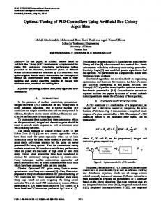
Fig I . Process step response From the equation (6),one can see that once the parameter a increases, the proportional gain k, arises which results
in a big PID control action; On the contrary, the similar results can be made too. Therefore, according to the step response (shown as in Fig.l), one can address the following conclusions for tuning the parameter a , At the beginning (point a,),there is a big system error, therefore, a big control action is desired in order to achieve a fast rise time. To produce a big control signal, the PID controller should have a large proportional gain, a large integral gain and a small derivative gain. Thus, according to the relations between the tuning the parameter a and the proportional gain k, , integral gain Ti and derivative gain T d , one should give a big value a ; Around the point 6,in Fig. 1, a small control action is expected to avoid a large overshoot, and a small value a is requested; Along with the decreasing of system error gradually, the control action should go to a stead state, therefore, the tuning parameter a should not be regulated again. Form the above analysis, the tuning parameter a should be reduced h m a big value to a small value gradually during the step response. Since fuzzy method has the ability of reasoning from the system error and the change of error, it can be utilized on-line to regulate the parameter a properly. The detail of the approach is to be presented in the next section. 111. THE PROPOSED FUZZY INFERENCE METHOD FOR TUNING THE PARAMETER (I
Fuzzy sets theory is first introduced by Zadeh in 1965 [IO], and has been applied in the industrial process control successhlly. Recent years, fuzzy logic has been used to tune the parameters of a PID controller [ I l l , and good improvement in the process response is achieved. During the design procedure of fuzzy PID controller, the human expertise in controlling a process is represented as fuzzy rules or relations. This knowledge base is used by an fuzzy inference mechanism, in conjunction with some knowledge
1110
Fuzzy Inference
Setpoint
Output
Fig. 2. Fuzzy self-tuning PID controllel of the state of the process in order to determine fuzzy control action on-line. The schematic diagram of a fuzzy self-tuning PID controller used in this paper is shown in Fig. 2. Where, the inputs of the fuzzy inference mechanism are the error e and the change in error Ae , and the suitable parameter a for tuning the PID settings is given hy the output of the fuzzy inference system. In this paper, four fuzzy sets (Z, S , M, and B) are considered for both error and its change. Where, 2 represents approximately zero, S , M and B denote small, medium and big respectively. Two fuzzy sets (S, B) are used for the output variable a . The error (e) and the change in error ( Ae) are normalized with respect to their maximum values. Therefore, their absolute values can be taken during the fuzzy inference. The triangular-type membership function is adopted in this paper for e, Ae and specified as in Fig. 3. The sigmoid-typemembership function is used for a and specified as in Fig. 4.
The grade of the $embership functians p and the Output variable a has the following relationship: p s ( a ) =l/(l+exp(-ZO(a-0.5))) for Big (7a) or p s ( a ) = l-l/(l+exp(-ZO(a-0.5)))for Small, (7b) The fuzzy rule base can he extracted from operator’s expertise or the step response of the process. In this paper, the step response of the process is used. According to the relationship between tuning parameter a and the step response, the followhg Fuzzy rules can be addressed. At the beginning (point a,in Fig. I), to produce a big control action, the tuning parameter, a can he represented by a fuzzy set Big. And the corresponding rule can be described as IF e is B and Aqis Z THEN a is BIG. Around the point b , in Fig. 1, a small a is requested for avoiding a large ov&shoot and the corresponding fuzzy rule is : IF e is Z and Ae :is B THEN a is SMALL. By the analysis, the whole fuzzy rule base for the tuning parameter a can be’summarized in Table 1. Tableil Fuzzy tuning rules for
a
In Table 1, all of the tuning fuzzy rules have the following description: Q: IF e is A i and Ae is B, THEN a is Ci Where, A,, B, and C, are the fuzzy sets. Using the simplified fuzzy reasoning method [I I], the agreement of the ith rule can be calculated by the product of the member function values in the antecedent part ofthe rule: ht = ~4 ( e ) . p B , ( & ) (8)
Fig. 3. Membership function o f e and Ae
where pA,is the membership function value ofthe fuzzy set Ai determined by the current input value e ; and pB,is the
0.4
a
0
0
0.2
0.4
0.6
0.8
?
Fig. 4. Membership function of the output a
membership function’value of the fuzzy set B, determined by the current input value Ae. For each h i , the corresponding output of the fuzzy rule can be calculated from Eq. (7a) or Eq. (7b) as ai =-0.051n(l/h;-1)+0.5 for “a isBig” (W or a; =-0.051n(l/(l-h;)-1)+0.5 for “a isSmall” (8b) Then the centroid method of defuzrification is used to get the crisp value of a from the fuzzy variables. the output value of f u u y inference system is calculated by
1111
a‘ =
hiai
/E hi
(9)
l i Here, ai is the value of a’ corresponding to the degree i
hi for the ith rule. According to the analysis results in previous section, the tuning parameter a should he greater than 1, and should be reduced from a big value to a small value slowly during the transient response process. Therefore, in this paper, the true value of a is determined as following a(k)= 1.1+ A ( k ) (10) A(k) = A ( k - l ) . a ’
1
where A(0) is a parameter selected by the user, it gives
the maximal value of a . After determining the parameter a , the PID controller parameters can be calculated by using the equation (6). IV. SIMULATION RESULTS Consider the integrating plus time delay process used in [I], which is described by the following transfer hnction G(s)=k-
e-* S
where, in nominal case, k=0.0506 , and 7 = 6 . The proposed method will be evaluated using this process. To compare the performance to the other previous work, the corresponding PID controller settings are given as followings, respectively, Visioli 191: k, = 4.5, T, = 8.94 and Td = 3.54; Luyben method [7]: k, =2.5639 ,
= 2.0123
7 = 7 and r = 8 , respectively. Fig. 6 and Fig. 7 show the results of servo responses. The responses are obtained for the regulatory problem as shown in Fig. 9 and Fig. IO. Visioli method gives an oscillatory unstable response when 7 = 8 both in servo response of regulatory response. The comparison results of ISE values are also given in Table 2. For the servo problem, the presented method gives robust responses and is superior to the method of [I], and the Luyben’s method gives the best robust performance. However, for regulatory problems, the performance of the presented method is better than that of [7], [7], and is equivalent to that of [I]. From the views of control theory, the servo problem is contradictory to the regulatory problem, and their performance need to he trade-off at some degrees during the design of a controller for the given process. From this point of view, the performance of the presented method in this paper gives a more effective compromise than that of others mentioned in this paper.
Table 2 Comparison of integral square error for the five methods
I
I
ISE for servo
I
ISE for regulatory
I
=56.32 and
Td ~ 3 . 5 6 1and with a first-order filter time constant as 0.382; Chidambaram and Sree[l]: k, = 4.0664 , = 27 and
T, = 2.7 with a = 1.25 ; Wang and Cluett [SI: k, Td = 1.5674 ;
( r = 6 ) , whereas the actual values in the simulations are
, T,=31.203 and
The performance of above PID controller and the presented method for the nominal process model are shown in Fig. 5 and Fig. 8. The servo responses are shown in Fig. 5 . The servo response of the proposed controller is slightly better than that of Chidambaram and Sree [l], and is better than that of Visioli [9]. The regulatory responses are shown in Fig. 8. The regulatory response is the best for the method of Visioli [9], since the setting was obtained by minimizing ISE for regulatory problem. In Table 2, the comparison of ISE values is given for the above method and the modified method. Obviously, for the regulatory problem, the presented method is better than that of [7] and [SI. The robustness of the proposed controller is studied by using perturbation in time delay T . The controller settings are those calculated for the process with nominal time delay
Remark: PID controllers are designed for * means unstable response. 2.5
7
= 6;
I - .. Present visioli(2ml)
-.
il
Chidambaram and SreepOO3)
- .. Luyben(1997)
nl
I
I
Fig. 5 . Servo respanre of the process for different methods ( 7 = 6 )
1112
I
3
I-
0.E Present
0.4
-. Chidambaram and SreepOm)
-.
Chidambaram and Sree(Z003) Wang and Cluetl(1997)
2 0.2 G
uO
50 ((sec.)
im
150
Fig. 6. Servo response of the process for different methods ( r = 7 )
-0.4
0
Fig. 9
50
100
150
200
250
300
'&.) Regulatory response o e p OCCEE for different methods ( r = 7 )
1
c
O
O'
MO
,(sec!$
300
250
Fig. 7. Servo response of the process for different methads ( r = 8 )
-1' 0
50
la,
150 [(sec.)
200
250
300
Fig. IO. RegulatoryresponseofIhe process for different methods ( r = 8 )
0.6 V. CONCLUSIONS
-.
Based on the simple method proposed by Chidambaram and Sree in [l], a modified approach is presented in this paper. The method applies fuzzy inference with simple mles to compute the tuning parameter a on-line. That avoids the difficulty in selekting a suitable parameter a in Chidambaram and Sree's method [I]. The comparison of performance for an integrating process is performed. The results validate that the development performance is achieved.
Chidambaram and Sree(2003)
REFERENCES
-0.1 O
'
loo ,(sec!?
200
250
Fig. 8. Regulatory response ofthe process for different methods (
300
r = 61
[I] M. Chidambaram and R. P.Sree,"A simple method of tuning PID controller^ for integratoddead-time processe~,'' Computers and ChemicolEnginerrig, vol. 27,211-215,2003, [2] C. C. Yu,Auto-IuningofPID Controller. Berlin: Springer, 1990.
1113
[3] J. H. Park, S.W. Sung, and I. Lee, “lmpmved relay auto-tuning with static loaddisturbance,” Aulomorico, vol. 33,111-715, 1997. r for 141 R. Srividya and M. Chidambaram, “On-line c ~ n t r ~ l l etuning integratorplus delay processer,”Procesr.ConrrolQuoi.,vol. 9,59-66 1997. [SI I. LI Chien and P. S. Fruehauf, “Consider IMC tuning to improve oerfomance.”Chem. Enc. vol. IO.. 33-41.. 1990. ” Pror.. ” _ [6] B. D. Tyreus and W. L. Luyben, ”Tuning PI c~ntrollen far integratorldead-lime processes,” I d . Emg. Chem. Res., vol. 31, 2625-2628, 1992. Controllers [7] Luyben, W. L. Tuning Proportional-Integral-Derivative for IntegratodDeadtime Processes. Ind. Eng. Chem. Res. 1996, 35, 3480-3483. l e rintee.ratine. ~ . . .181. L. Wane. and W. R. Cluen “Tuning PID ~ ~ n t r ~ l for processis,’’ IEE Proc. CTA, vol. 14i, 385-392, 1997. 191 A. Virioli. “Ootimal tunine of PTD controllers for inteeml and ” unstable processes,” IEE Proe Conrrol nteory Appl , YOI148, 180-184.2001 [IO] L A Zadeh, “ F u q Sets,”lnformonon ondConrro1, voI 8,338-353, 1965. [ I I ] Z. -Y. Zhaa, M. Tomizuka and S.Isda, “ F u q gain scheduling of PID controllers,” IEEE Trans. on Syslem, M m and Cy6ernericJ. vol. 23, 1392-1398, 1993.
..
1114