Keywords: - Neutral Point Clamped Converter, Modulation strategy, Electrical conversion, Multilevel chopper. 1 Introduction. Due to the incisive competition in ...
A direct modulation of electrical conversions for a multilevel NPC chopper B. François, J.P. Hautier L2EP - Ecole Centrale de Lille, Cité scientifique, B.P. 48, 59651 Villeneuve d’Ascq CEDEX, France
Abstract: - In this paper the methodology of the Causal Ordered Graph (COG) is used for the modelling of a Neutral Point Clamped (NPC) chopper. The obtained modelling shows that high-voltage multi levels are obtained by combination of two different three-level functions which are called conversion functions. Therefore a novel PWM strategy is deduced. It consists of a separated modulation for creating two fictive modulated voltage systems via the direct width modulation and the position setting of both conversion functions. The redundancy of different switches configurations for the voltage half value allows to use a particular modulation technique which limits the deviations of the capacitor voltage. Switching patterns are deduced and a decoupling control of the capacitor voltage and the supply current is designed. Keywords: - Neutral Point Clamped Converter, Modulation strategy, Electrical conversion, Multilevel chopper
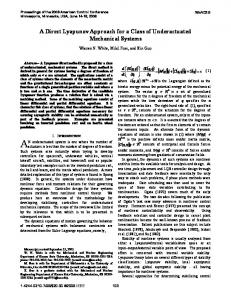
1 Introduction Due to the incisive competition in mass transportation, many innovations are considered and experimented for the economic improvement of the railway traction system [5]. A main aspect is in the use of new and more powerful electrical drives. Recently, in the context of the reduction of the filtering elements, the replacement of the classical chopper (Fig.1) by a flying cell chopper operating in voltage multilevel has been investigated [1]. It enables a diminution of the high-voltage harmonic magnitude and, in addition, the obtained blocking voltage of force-commuted semiconductor devices are least [2]. In this context, this study concerns the use of a Neutral Point Clamped (NPC) chopper as another multilevel power structure. dc bus vV
dc ac ac
dc dc
dc
Rectifier
Chopper
ac machine
The power structure of the considered multilevel converter is composed by a two compact commercial NPC commutation cells (Fig. 2). In fact with a such device too much semiconductors are used to implement an unidirectional power flow. Unnecessary semiconductors will be suppressed for the industrial development of this power converter. The converter is fed by a dc current-source controlled voltage rectifier and so the voltage source (us) is constant. Two outputs will be considered: the supply current (is) which is influenced by the modulated multilevel voltage (um) and the capacitor voltage (us2) which is influenced by two modulated currents (im1, im2) and the rectified current (ir). Our attention is being directed towards enhancing the performance of the control system. In this purpose, we propose a direct modulation of electrical conversions..
Inverter dc ac
ac machine
Inverter
Fig.1: Representation of the power architecture
2 Analysis of the NPC cell 2.1 Fundamental principles
In order to ensure a correct multilevel operating, the control system must maintain the same voltage value across capacitors: us = us = us . (1) 1
2
f1c
•
f2c
2
us2
u s1
D1c
T2c
um10 T3c
T3c
is
T4c
im 1
o
T4c 0 0 1
um O1
um10 f1c us 1 0 us2 0 0
f2c 0 1 0
f3c 0 0 1
Table 1:
The output voltage (um10) may be equal to the full level (us) by switching on the sets {T1c, D1c} and {T2c, D2c} or the half level (us/2) by switching on the sets {T2c, D2c} and {T3c, D3c} or the zero level by switching on the sets {T3c, D3c} and {T4c, D4c}. Therefore, this clamped commutation circuit is equivalent to a commutation circuit whose one ideal switch among the three is at anytime switched on (fig. 4). The switch states are called connection functions. If frc=1, the corresponding ideal switch (and so corresponding transistors) is closed. Otherwise, if frc=0, it is open. The index r corresponds to a row and c to a commutation circuit. Connection functions are easily deduced from gate signals by following logic relations:
O2
f 11
f 12
f21
f22
f31
f32
us
Fig. 3: Equivalent commutation circuit
T3c 0 1 1
(2)
By using two NPC cells to chop voltage sources, we get an equivalent matrix ideal converter (fig. 5).
T4c
T2c 1 1 0
•
f1c=T1c, f3c=T4c, f2c=T2c.T3c
T2c
us2
T1c 1 0 0
•
Fig. 4: Equivalent commutation circuit
im 2 C2
•
o T1c
•
f3c
im 1 C1
um10
us
Looking at the first clamped commutation circuit (fig. 3). us
•
im 2 us 2
0O
Fig. 5: Equivalent representation
We can write:
v10 = (v1 - v0 ) = f11 .us + f 21 .us 2
(3)
We deduce the following expression of the modulated voltage: um = v10 -v20 = ( f11 − f12 ) .us + ( f 21 − f22 ) .us 2 (4) Both commutation cells and the particular dc/dc operating imply four different configurations of switches and modulated levels. They are coded by three connection functions (table 2). In balancing conditions ( us1=us2 = us ), we 2
effectively get two different configurations to get an half-level voltages (2 and 6 as example). They can be chosen to load or disload one capacitor in order to ensure the balancing condition. This is the key of the exposed modulation.
Patterns
Circuit 1
f11 f21 f31 1 2 3 4 5 6 7 8 9
1 1 1 0 0 0 0 0 0
0 0 0 1 1 1 0 0 0
0 0 0 0 0 0 1 1 1
Circuit 2 Three Levels Modulated voltage
f12 f22 f32
m1 m2
1 0 0 1 0 0 1 0 0
0 1 1 -1 0 0 -1 0 0
0 1 0 0 1 0 0 1 0
0 0 1 0 0 1 0 0 1
Balancing condition
0 us1 us1+us2 -us1 0 us2 -us1-us2 -us2 0
0 -1 0 1 0 1 0 -1 0
→ → → → → → → → →
0 ½ .us us -½ .us 0 ½ .us -us -½ u. s 0
To implement a chopper function, negative voltage levels are prohibited and so configurations 4, 7 and 8 are unnecessary. Moreover, only one configuration can be used to create null conversions. So, in fact, three different NPC-based structures can be designed to obtain a multilevel chopper function. As example if we use he configuration 5 to force a zero modulated voltage, we get a simplified table (table 3). 0 1 1 0
1 1 1 1
1 0 0 1
0 0 0 0
0 0 0 0
1 1 0 0
1 1 1 1
0 0 1 1
0 1 1 0
um
0 0 -1 us1 0 us1+us2 1 us2
→
0 ½ .us us ½ .us
→ → →
Balancing condition
Table 3: Reduced NPC based structure
By replacing all closed semiconductors by wires and by suppressing all opened semiconductors, we obtained a first simplified NPC-based structure (figure 5). The two other possible structures require more semiconductors and will not be much more detailed in this paper. im 1
ir us
T 11
C1
T 22
L um
im 2
is R
us2
C2
If capacitor voltages have constant values, it appears that the voltage um is shaped through two conversion functions as:
um = um1 + um2
(5)
um1 = m1 .us (6), um 2 = m2 .us 2
(7)
with
3 Structures of NPC based choppers
T11 T21 T31 T41 T12 T22 T32 T42 m1 m2
4.1 Modelling of voltage conversions
with
Table 2: Extended NPC based structure
5 2 3 6
4 Modelling of the reduced NPC chopper
T 31
T42
Fig. 5: Power structure of the reduced NPC based structure
m1 = f11− f12 = f11 (8),
m2 = f 21 − f 22
(9)
and m1{0,1}, m2{-1,0,1} We have so defined two different functions called conversion functions. If their position and their width are modulated, the modulated voltage and also the modulated current are directly influenced. In a same way, we can express the two modulated currents as: im1 = m1 .is (10.4), im2 =m2.is (11.b)
4.2 Averaged modelling The purpose of the control system is to regulate the mean value of the modulated voltage () during each modulation period in order to get a constant value of the load current (is). The mean value of the modulated voltage during the modulation period (Te) is expressed as: 1 (k +1 ).Te um(t) = . um(t).dt Te k.Te Te− > 0 with k ∈Ν . This quantity is linked to conversion functions and voltage sources (6) and (7) which are assumed to be nearly constant during the modulation period [4]:
∫
um = m1 .us + m2 .us 2
(12)
The mean value of a conversion function is therefore defined as: (k +1).Te (13) mr(t) = 1 . mr(t).dt Te k.Te
∫
Te−>0
5 Design of the control system 5.1 Control scheme The ordering of all implicated relations following the input output transfer and the causality respect gives the representation depicted fig. 6. Relations are represented by a balloon with inside it number. Causal relations are characterized by an integration operator and so contain an unidirectional arrow. Other ones contain a bi-directional arrow which means the existence of a direct inverse relation. From this representation, we see that the current (is) can be regulated to a reference (isref) by a correct setting of the modulated voltage (um) and a closed loop control whose relation is named (21)-1. This multilevel voltage is built by two three-level modulated voltages (um1 and um2) which will be set through two conversion functions (mr). This freedom degree will be used to calculate conversion functions in order to hold a constant value of the capacitor voltage (us2). The average modelling produces equivalent continuous conversion functions () of discontinuous conversion functions. On the other hand, in the control system, we will have to produce a discontinuous reference conversion function (mr_ref) from a desirable continuous reference conversion function (). On the other hand, in the control system, we will have to produce a discontinuous reference conversion function (mr_ref) from a desirable continuous reference conversion function (). f11 T 11 B31 T B22 T B 42 T B
This is implemented by two pulse position and width modulators (PPWM) because this technique keeps unchanged the mean value of discrete and continuous functions during a modulation period. Finally, a logic connection controller processes the switching signals via an inverse mapping of table 2.
5.2 Gate signal controller The gate signal controller implements the inverse Boolean mapping of equation (2): T11= fref11 , T31= fref21 , T22= fref22, T42= fref32 (2) –1
5.3 Connection controller The connection controller is simply an EPROM reading process of the inverse mapping of table .
5.4 Pulse Position and Width Modulator Two pulse width and position modulator (PPWM) are required to build conversion references from average conversion references (continuous signals) by mean of the conservation of the averaged value. Previously, the operating of this modulator has been described by Petri nets [3]. Each modulator is able to locate the pulse in the modulation period. Each pulse position (p1 and p2) is calculated by a “Position setting” block which takes into account the available place and possible wrong patterns (as example m1_ref = m2_ref = 1). us
m1
(8)
(24)
(6)
um 1
um
(5)
is
(21)
(10)
is us2
(2)
f 21
m2
91)
(24)
um 2 is
f 22
(7) (11)
im 2
im 1 (14)
ic2
us2
(15)
us Multilevel chopper modelling Control architecture T 11_ref T 31_ref T 22_ref T 42_ref
us us 2 m 1_ref
(2)
-1
Gate Signal Controller
(24) -1
(6 & 5) -1
u m _ref u mref
f c_ref Table 1
Coordinator
PPWM
Connection Controller
m 2_ref
(24) -1
(7 & 5) -1
Fig. 6: COG of the flying capacitor chopper
(21) -1
is
is _ref
With such modulators, reference conversion functions are made equal to mean value conversion functions: = . || .Tm
mr_ref 1
(q+1) .Tm
q .Tm t1 1
-1
t
t2 3
2
6
5
t6
t5
pr_ref(q.Tm) .Tm t3
Fig. 9: Real time evolution of the modulated signal
5.5 Capacitor voltage balancing 5.5.1 Pattern selection Modulated currents cause unwanted deviations of capacitor voltages. The capacitor C1 voltage decreases in case of fig. 8 (a) and decreases in case fig. 8 (b) as the voltage us is hold constant. So, for a wished half level of the modulated voltage, two configurations are possible and will affect the capacitor voltage. In order to limit the capacitor deviations we have designed a modulation strategy which consists to alternate successfully one loading pattern and one disloading pattern when applying the half voltage level. Two cases are now considered for the calculation of the durations of electrical conversions. (a) : pattern 2
us
5.5.2 Full level modulation A full level modulation occurs when the reference of the modulated voltage is superior to the theoretical half level ( > us/2 ). It is implemented by using only the full level and one half level. With a such modulation no zero voltage is applied to the load (fig. 9). We recall that the modulated voltage reference is decomposed as a sum of two kinds of conversions: conversion of the full level and conversion of the half level as: = + 1 . us 2
If us2 < us , the pattern 2 must be chosen to
2
increase this capacitor voltage. In order to assume no zero conversions inside the modulation period, a delayed modulation of the two conversion functions must be implemented and, so, the following constraint must be satisfied: + =1 1
u m _ref =m _ref us t
(b) : pattern 6
is
is us
in table 3) will be used to implement the half level modulation. For higher values of the modulated voltage reference, it is preferable to avoid the use of the zero pattern. Thus the full level modulation will be designed by switching among patterns 3 and 5 in table 2.
•
•
•
•
us
1
•
•
•
•
us
•
: Disload : Load
Tm
•
•
•
m 1_ref 1
1
•
•
•
•
t m 2_ref
|m 2_ref |.Tm
1
•
•
•
•
•
•
•
•
Fig. 8: Effect of the half level modulation onto capacitor loads
t -1
Delayed Modulation
Simultaneous Modulation
Fig. 10: Full level modulation
For small values in the modulated voltage reference, the best choice is to select only voltage half-values because they produce the smallest changes in the current. Two kinds of voltage levels (us and us/2) and three patterns (No5, No2 and No6
By taking into account this constraint into the preceding equation, we get: =2. − 1 =2−2. us us
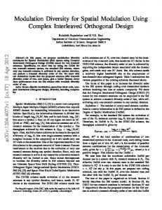
As shown on fig. 11, the capacity C2 achieved a maximum rated value at 0.22 s when the modulation strategy is inactive. Thanks to the exposed direct modulation strategy, this voltage is attenuated in transient operation and set to the half of the full level (us). Further works are oriented to the study of the quality of stabilisation following different loads and different operating points.
If us2 > us , the pattern 6 is chosen to decrease
2
the capacitor voltage. A simultaneous modulation of both conversion functions is implemented by setting: − 1 =1 and =2. us
400
5.5.3 Half level modulation
us
If us2 < us , we need only the half level as shown
350
2
on fig. 10. The pattern 2 will be chosen in order to increase the capacitor voltage. Therefore we get:
300
=0 and =2. us
2
strategy
200
Otherwise, the pattern 6 is chosen in order to decrease the capacitor voltage and a simultaneous modulation is used. In this case, conversion functions have different signs but have the same modulus: = − 1 . 2
m ref
us2 with the modulation strategy
150
100
50 0.1
0.15
0.2
0.25
0.3
0.35
0.4
0.45
t(s) 0.5
Fig. 11: Start with and without the modulation strategy
1
t Tm m 1_ ref
: Disload : Load
1
t m 2-ref
us , without the modulation
250
|m 2_ref |.Tm
1
t -1
Delayed Modulation
Simultaneous Modulation
Fig. 10: Half level modulation
By taking into account this constraint into the preceding equation, we get: and =−2. _ ref =2. us us
7 Simulation results and conclusion The reduced NPC based structure and the exposed modulation strategy has been simulated with a closed loop control of the resistive load voltage to 100V with following elements: C1=C2=15mF, L=10 mH, R=10Ω.
References [1] Meynard T., Foch H., “ Dispositif électronique de conversion d’énergie électrique ”, patent: FR N°9109582, Europe, Japon, USA, Canada N°9200652 [2] Wilkinson R. H., Meynard T., Richardeau F., Enslin J.H.R., “ Dynamic control and voltage balance of multilevel converters: Large signal one-cycle response ”, EPE’99, Lausanne, CD [3] B. François, J.P. Hautier, “ Pulse Position and Pulse Width Modulation of Electrical Power Conversions: Application to a Three-Phase Voltage-Fed Inverter ”, 3rd International Symposium on Advanced Electromechanical Motion Systems: ELECTROMOTION 1999 [4] Ralaivao H., François B., Hautier J.P., “A Strategy for Modelling and Controlling a Single Phase Multilevel Inverter in Mean Values”, Progress in Simulation, Modeling, Analysis and Synthesis of Modern Electrical and Electronic Devices and Systems, p. 348-353, World Scientific Engineering Society Press, ISBN 960-8052-08-4 [5] Fuchs A., Friedrich T., Marquardt R., “ Advanced multi-system locomotives using 6.5 kV power semiconductors ”, EPE’99, Lausanne, CD