1
A Distributed and Autonomic Virtual Network Mapping Framework Ines Houidi, Wajdi Louati, Djamal Zeghlache,
Abstract Network Virtualization is a promising concept to diversify the Future Internet architecture into separate Virtual Networks (VN) that can support simultaneously multiple network experiments, services and architectures over a shared substrate network. To take full advantage of this paradigm this paper addresses the challenge of assigning virtual networks to the underlying physical network in a distributed and efficient manner. This work reports on an implementation and evaluation of a distributed and autonomic framework with algorithms responsible for mapping virtual nodes and links to the physical resources. A distributed algorithm responsible for load balancing and mapping virtual nodes and links to substrate nodes and links has been designed, implemented and evaluated. A VN Mapping Protocol is proposed to communicate and exchange messages between the agent-based substrate nodes to achieve the mapping. Results of the implementation and a performance evaluation of the distributed VN mapping algorithm using a Multi-agent approach are reported. Index Terms Virtual Networks, Distributed Mapping Algorithm, Autonomic Framework, Virtual Network Mapping Protocol, Multi-Agent System.
GET-INT Technical Report 07009 RS2M (TR-07009-RS2M), November 2007, Ines Houidi (
[email protected]), Wajdi Louati (
[email protected]) and Djamal Zeghlache (
[email protected]) are with the Institut National des Telecommunications, 9 rue Charles Fourier 91011 EVRY Cedex, France.
I. I NTRODUCTION
N
ETWORK Virtualization has recently received considerable attention in both academia and industry as an important enabler for designing the Future Internet architecture [1], [2]. The Network
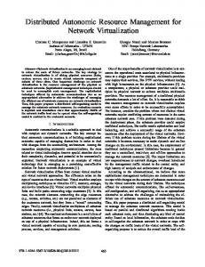
Virtualization concept has been proposed as a potential solution for diversifying the Future Internet architecture into separate Virtual Networks (VN). The VNs can support simultaneous network experiments, services and architectures over a shared substrate network [3], [4], [5]. A Virtual Network is a group of Virtual Nodes (e.g. virtual routers) interconnected via dedicated Virtual Links over a substrate network. As depicted in the figure 1, multiple virtual networks may share the same underlying physical network. The set of virtual nodes and virtual links forming the VN should be assigned to a specific set of Substrate Nodes and Substrate Paths, respectively. A Substrate Path is a logical path between two substrate nodes which may be a single substrate link or a sequence of substrate links.
Fig. 1.
Mapping of Virtual Networks to a shared substrate network
The Virtual Network set up is achieved by selecting the best and optimal network topology from the physical substrate comprising both virtual nodes and links. Mapping multiple virtual networks into a shared physical infrastructure represents a significant challenge that has been addressed in many research studies. Finding the optimal VN mapping solution that achieves the best load balancing among the substrate resources and satisfies multiple constraints can be formulated as an NP-hard problem. A number of proposals and heuristic algorithms have been put forward to address the VN assignment/mapping problem [6], [7], [8], [9]. The objective is to provide effective methods and algorithms for mapping a virtual network to specific nodes and links in the substrate network in a cost-efficient way. In these proposals, the VN mapping algorithm is carried out in a centralized manner. A central entity is responsible for receiving VN requests and for assigning a set of virtual nodes to a set of substrate nodes. However, the centralized approach may present serious limitations on scalability, efficiency and resiliency of VN provisioning and
3
management. This becomes a challenge especially when the substrate network is a highly dynamic and changing environment (e.g. node/link failures, node mobility, etc). To deal with the dynamic aspect of a substrate network, there is a real need to decentralize the substrate control and management to efficiently map VNs onto the substrate while reducing complexity and improving scalability. The objective of this work is to decentralize the decision-making for VN mapping among all substrate nodes. To achieve this purpose, the substrate nodes should be autonomic to decide which mapping, i.e. decisions/actions, to undertake automatically and without human intervention. This is exactly the motivation of this paper whose goal is to design a Distributed and Autonomic Mapping Framework responsible for self-organizing and self-managing the substrate nodes supporting the VNs. Consequently, the VN mapping algorithm is carried out in a distributed way among the autonomic substrate nodes. Furthermore, the current proposals [6], [7], [8], [9], [10] do not address the problem of how to carry out their proposed VN mapping algorithms with respect to the design and implementation of the mapping framework, mechanisms and protocols used to exchange substrate messages, etc. This paper provides the design and implementation of the Distributed and Autonomic VN Mapping Framework based on the Multi-Agent based approach [13] to ensure distributed negotiation and synchronization between the substrate nodes. These nodes handle autonomous and intelligent agents which exchange messages and cooperate to carry out the distributed VN mapping algorithms. A Virtual Network Mapping Protocol is proposed to enable communications between the agent-based substrate nodes. Performance and scalability results of the distributed and autonomic VN mapping framework developed using the Multi-agent based approach are reported. The remainder of this paper is organized as follows. Section II of this paper summarises related work. Section III presents the network model and the VN mapping problem. Section IV presents the design of a VN mapping algorithm. Section V describes the design of an autonomic and distributed mapping framework for the substrate. Section VI presents the design of a distributed VN mapping algorithm.The implementation and evaluation of the proposed algorithm based on multi-agent based approach is reported in Section VII. II. R ELATED W ORK VN mapping algorithms: A number of heuristic greedy algorithms [10], [6], customized algorithms [9] and iterative mapping process [8] have been put forward to efficiently assign VN to substrate resources.
4
Y. Zhu and M. Ammar [6] proposed heuristic greedy algorithms to maintain low and balanced stress among all substrate nodes and links during VN assignment process. The aim of greedy algorithms is to assign virtual nodes to substrate nodes with maximum available resources. The overall objective is to achieve near optimal VN mapping solutions. In [8], [9], authors propose to use customized mapping algorithms to map special VN topologies (e.g. hub-and-spoke and backbone-star based VN topologies) in an optimal manner. J. Lu and J. Turner [8] proposed an iterative refinement procedure to map constraintbased virtual networks onto a common physical substrate. Their objective is to find the least-cost virtual network topology that can handle any traffic pattern allowed by a set of traffic constraints. Discussion and motivation: In these proposals, the VN mapping algorithms are carried out in a centralized manner. A central entity is responsible for selecting clusters from the VN topology (e.g. star cluster [6]) and for mapping the selected clusters to the substrate. The central entity should maintain up to date information about the substrate network (e.g. available resources) to make the appropriate VN mapping decisions (i.e. centralized decision making). However, maintaining up to date information about the substrate network in a centralized way suffers from scalability limitation, high latency and serious delays in making decisions especially when the underlying physical network is a highly dynamic and changing environment (e.g. node joining/leaving). Hence, the first objective of this work is to distribute the substrate control and management over the substrate nodes. These nodes should exchange messages, also called knowledge, and cooperate in a structured way to ensure decentralized decision-making for VN mapping. To achieve self-organization in distributed environments, the substrate nodes should control, manage and organize themselves to reach the VN mapping objectives. This paper provides the design requirements of autonomic substrate nodes to handle decentralized decision-making algorithms for VN mapping automatically and without human intervention. III. V IRTUAL N ETWORK M APPING M ODEL AND P ROBLEM
FORMULATION
A. Substrate Network Model The substrate network can be represented by a weighted undirected graph Gs = (N, L), where N is the set of substrate nodes and L is the set of substrate links between nodes of the set N . Each substrate node ns ∈ N is associated with the capacity weight value C(ns ) which denotes the available capacity of the physical node ns . Each substrate link ls (i, j) ∈ L between two substrate nodes i and j is associated with two non-negative values: 1) an additive weight value w(ls (i, j)) which denotes a set of parameters
5
including the cost and delay of the substrate link and 2) a capacity weight value C(ls (i, j)) which denotes the available bandwidth capacity associated to the substrate link. Let ψ be a set of substrate paths in the substrate network Gs . The available bandwidth capacity C(P ) associated to a substrate path P ∈ ψ between two substrate nodes can be evaluated as the minimal residual bandwidth of the links along the substrate path:
C(P ) = min C(ls (i, j)) ls (i,j)∈P
(1)
The weight (i.e. cost, delay) of the substrate path w(P ) can be measured as the sum of all link weights along the path P :
w(P ) =
X
w(ls (i, j))
(2)
ls (i,j)∈P
B. Virtual Network Model Users/customers should send requests to the substrate provider to set up on-demand VN topologies with different capacity parameters over the shared substrate. The VN request can be represented by a weighted undirected graph Gv = (Nv , Lv ), where Nv is the set of virtual nodes and Lv is the set of virtual links between nodes of the set Nv . Each virtual node nv ∈ Nv is associated with a minimum required capacity denoted by C(nv ). Each virtual link lv ∈ Lv between two virtual nodes is associated with a capacity weight value C(lv ) which denotes the minimum required bandwidth capacity of the virtual link lv . In this work, the VN request is represented by the triple Req = (Gv , Vv , Mv ) where Vv and Mv denote a node capacity vector and a link capacity matrix, respectively, associated to the graph Gv such that: •
Vv =[C(niv )] is the minimum required capacity vector for virtual nodes niv , where 1 ≤ i ≤ |Nv |.
•
Mv =[C(lv (i, j))] is the minimum required bandwidth capacity matrix for virtual links lv between nodes niv and njv , where 1 ≤ i, j ≤ |Nv |.
C. Virtual Network Mapping Problem Description Based on the substrate and virtual network models, the challenge is to find the best mapping between the virtual graph Gv and the substrate graph Gs . This mapping, denoted by MAP, should achieve the best load balancing in the substrate network resources, with respect to the capacity constraints, while reducing the cost.
6
1) Node Mapping: Let M APN : Nv → Ns ⊆ N denotes a mapping function between virtual nodes and substrate nodes, where Ns = {ns ∈ N | C(ns ) ≥ minnv ∈Nv {C(nv )}} 2) Link Mapping: Let M APL : Lv → φ ⊆ ψ denotes a mapping function between virtual links and substrate paths, where φ = {P ∈ ψ | C(P ) ≥ C(lv ), ∀ lv ∈ Lv } 3) Motivation and Objectives: Finding the optimal VN mapping solution that achieves the best load balancing among the substrate resources and satisfies multiple constraints can be formulated as an NPhard problem. Past research has proposed a number of heuristic algorithms [6], [7], [8], [9] to solve this problem. However, in the current proposals, the VN mapping algorithm is performed in a centralized manner. A central entity is used to receive VN requests and to select a set of substrate nodes able to support the virtual nodes. The substrate network can be very dynamic and always in evolution (e.g. node joining/leaving). To deal with dynamic aspect of a substrate, there is a real need to decentralize the substrate control and management. This is achieved by allowing substrate nodes to be able to decide which mapping actions to undertake. Consequently, the VN mapping algorithm should be carried out in a distributed way among the substrate nodes. The objective of this work is to design, implement and evaluate a distributed heuristic algorithm to efficiently assign virtual networks to a set of substrate network resources, while minimizing the network cost. To simplify the problem, we assume that the substrate network resources (e.g. CPU, bandwidth) are unlimited to accept and handle all VN requests. We also suppose that all VN requests are defined and specified in advance, i.e. Offline problem. IV. D ISTRIBUTED L OCALIZED V IRTUAL N ETWORK M APPING A LGORITHM A. VN decomposition Since VN topologies can become quite large, mapping the requested VN to the entire substrate at once is not feasible for latency and complexity reasons. One well known and viable solution, when conducted properly, is to subdivide the entire VN topology into a set of elementary clusters (e.g. path, tree and star clusters). This decomposition may reduce the complexity of mapping the entire VN topology since less virtual nodes and links are considered in each cluster mapping process. The VN decomposition provides also an efficient solution to deal with the dynamic aspect of a substrate. Indeed, when a change occurs in the substrate/virtual networks (e.g. node/link failures, congestion), it is more suitable to localize the concerned cluster and reassign it instead of reassigning the whole VN topology.
7
For instance, Y. Zhu and M. Ammar [6] proposed advanced algorithms to break up the VN topology into a number of connected sub-VN such as hub-and-spoke clusters. The hub-and-spoke (or star) topology is composed of a central node (i.e hub) to which multiple adjacent nodes (i.e. spokes) are connected. In a hub-and-spoke cluster, some spoke nodes may act as the hubs of other clusters. This paper focuses on the star based VN decomposition and addresses how to decompose and map the star topologies in a collaborative and decentralized manner rather than centralized as in the case of [6]. B. Collaborative and Distributed Decision Making for VN Mapping To deal with the dynamic aspect of a substrate, the idea of this work is to decentralize the decisionmaking process among all substrate nodes to decompose and map virtual networks onto the substrate. This is achieved by allowing substrate nodes to subdivide the VN into hub-and-spokes (i.e. star) clusters and plan which mapping decisions/actions to undertake. The distributed mapping of hub-and-spokes clusters to the substrate is recursively executed as follows (Algorithm 1): Algorithm 1 : Hub-and-Spokes Clusters Mapping 1. Find the substrate node with the maximum available resources (referred to as the root node) 2. The root node selects the Hub-and-Spokes Cluster from the VN topology (see Algorithm 2 for VN decomposition) 3. Assign the hub node to the root node 4. The root node determines the set of substrate nodes able to support the spoke nodes based on shortest path algorithm. 5. Remove the substrate nodes and paths already assigned to the hub-and-spoke cluster. 6. The root node selects the next root node: Go to (1)
Each substrate node designated as root will be responsible for selecting a hub-and-spokes cluster from the VN topology and assigning it to the substrate. The selection of the hub-and-spokes clusters from the entire VN topology is recursively performed as follows (Algorithm 2): Algorithm 2 : Hub-and-Spokes Cluster Selection 1. Find the virtual node with the highest capacity to make it the hub of the cluster. 2. Determine the neighboring virtual nodes directly connected to the hub node to represent the spoke nodes. 3. Remove the hub and spoke nodes as well as their corresponding links from the VN topology
8
The mapping of hub-and-spoke clusters to the substrate is carried out in a distributed way among the substrate nodes. The distributed VN mapping algorithm is considered as a cooperative task executed jointly by all substrate nodes via messages exchange. Indeed, each substrate node can make local decisions individually (i.e. virtual resources allocation) but should also communicate, collaborate and interact with others to plan collective mapping decisions to efficiently assign VNs to the substrate. This enables distributed localized mapping of VNs. To self-organize and self-manage the interaction, cooperation and negotiation between all substrate nodes, a Distributed and Autonomic Mapping Framework is proposed. The objective is to ensure distributed decision making (for VN mapping) among the substrate nodes based on global knowledge/view of the entire substrate and virtual network topologies. V. D ISTRIBUTED
AND
AUTONOMIC M APPING F RAMEWORK
In this section, a Distributed and Autonomic Mapping Framework is defined to self-provision and self-manage VNs according to high-level goals and policies (representing business-level objectives). This framework is used to map, in a distributed way, multiple VN topologies to the substrate network on behalf of the substrate provider. As shown in the figure 2, the proposed framework is composed of Autonomic Substrate Nodes (section V-A) interconnected to each other using a VN Mapping Protocol (section V-C). The autonomic substrate nodes should exchange control/signaling information needed to carry out the distributed VN mapping algorithm (section V-D).
Fig. 2.
Autonomic and Distributed Management Framework Architecture
9
A. Autonomic Substrate Nodes A substrate node designated as a root node is responsible for selecting the hub-and-spokes cluster from the VN topology and assigning it to the substrate. In a dynamic substrate environment, the root nodes should control and manage their virtual resources without human intervention. This section provides the design requirements of substrate nodes to allocate virtual resources to VNs in a dynamic and autonomic manner. The substrate nodes should be open, flexible, virtualized and autonomic to support dynamic VN mapping, provisioning and management. The Autonomic Substrate Node capabilities are [11]: •
Self-configuration : The Autonomic Substrate Node should be able to automatically configure and reconfigure itself and the supported cluster following unpredictable VN deployment and provisioning requests and external conditions. Since VN requests may arrive dynamically, the autonomic substrate node should re-configure itself at run time in accordance with arrival/departure of VN requests (e.g. virtual resources (re)allocation, etc).
•
Self-optimisation : The Autonomic Substrate Node should seek ways to optimise itself to improve its execution and to ensure that the node is running at optimum levels. The autonomic substrate node should share its virtual resources between multiple virtual nodes in efficient manner. In fact, the substrate node should not allocate large substrate resource to assign virtual nodes which do not really require important resources (e.g. spoke nodes which do not support important traffic volume).
•
Self-healing : To discover and repair localized problems and failures automatically in a substrate node (e.g. node and link failures), there is a definite need for an effective self-healing system. The self-healing system should monitor, analyze, diagnose and identify errors and failures without human intervention.
•
Self-protection : The Autonomic Substrate Node should be capable of identifying, detecting and protecting its resources from malicious attacks and inadvertent cascading failures. The Autonomic Substrate Node should maintain overall system security and integrity.
•
Self-awareness : The Autonomic Substrate Node needs detailed knowledge of its state (e.g. available capacity), components and behaviors and should be aware of its logical and physical resources that can be shared, isolated, allocated or borrowed. The Autonomic Substrate Node should monitor, maintain and adjust its operation, resources and components during VN provisioning.
As depicted in the figure 3, each Autonomic Substrate Node integrates an Autonomic Manager responsible for:
10
Fig. 3.
•
Design of an autonomic substrate node
Analyzing policies specified by the substrate provider. The policy rules maintain the VN topology as well as performance metrics associated to virtual nodes and links.
•
Supervising and monitoring (M) physical and virtual resources within the substrate node. The monitoring entity generates metrics that express the node state, capabilities and performance (i.e. availability of resources). These metrics are stored in a knowledge (K) data base.
•
Making decisions (D) in accordance with the local knowledge base. In each autonomic substrate node, the Decision entity is responsible for maintaining and executing the collaborative and distributed VN mapping algorithm introduced in the section IV-B.
•
Executing actions (E) in the substrate nodes (i.e. managed elements). For instance, if the autonomic substrate node is selected as a root node, it should allocate virtual resources to support the hub node, on the one hand, and determine the set of substrate nodes able to support the spoke nodes based on shortest path algorithm, on the other hand.
These four stages described above are achieved under a closed-loop control.
B. Multi-Agent based Autonomic and Distributed Mapping Framework Since the Multi-Agent System approach [13] represents a good tool to build modular and autonomous systems capable of operating in dynamic and distributed environments, we propose to implement the Autonomic and Distributed Mapping Framework based on autonomous and intelligent Agents [14]. The Multi-Agent based framework ensures distributed negotiation and synchronization between the autonomic substrate nodes. These nodes handle autonomous and intelligent agents which exchange messages and cooperate to perform the distributed VN mapping framework and algorithm.
11
Fig. 4.
Design of an autonomic substrate node using agent based approach
As shown in the figure 4, an Agent based Autonomic Substrate Node is composed of three main components: a Knowledge Base, a Rule Base, and an Engine. The Engine is the active component in the Agent based Autonomic Substrate Node responsible for executing three phases: Perception (i.e. Monitoring), Making Decisions and Action (i.e. Execution). The autonomic manager explored in section V-A is performed by the Engine. The Knowledge Base maintains the state of the substrate node (e.g. available capacity of virtualized resources) and its environment (the state of the links directly connected to the node as well as the state of adjacent nodes). The Rule Base maintains a set of possible actions that an agent based substrate node should execute whenever rule conditions are satisfied. The making decision process consists in selecting the appropriate action, based on the knowledge and rule base, to be executed and applied in the substrate node.
C. VN mapping protocol A communication protocol, called Virtual Network Mapping Protocol, is defined in this section to exchange messages and information between all substrate nodes. The VN mapping protocol is based on five types of messages: START, NOTIFY, MSG, NEXT and STOP. These messages are sent and received asynchronously between substrate nodes to exchange information and organize the distributed algorithm iterations. The protocol messages are described as follows: •
START (VN Request): This message is sent from a synchronizer (e.g. substrate provider) to all substrate nodes to trigger and start the distributed mapping algorithm. The START message handles the VN request information (e.g. list of virtual nodes and links, capacities, etc).
•
NOTIFY (nv -id, ns -id): After assigning a virtual node nv to a substrate node ns , the substrate node
12
should notify the other substrate nodes about this mapping. The nv -id and ns -id represent the unique identifiers for the virtual node nv and the substrate node ns , respectively. •
MSG (ns -id, C(ns )): This message is used to exchange node capacities among all substrate nodes. Each node broadcasts its capacity to all other nodes.
•
NEXT: Once the hub-and-spoke cluster has been assigned, the root node supporting the hub should send a NEXT message to designate the successor root node to support the hub of a new cluster.
•
STOP: This message is used to stop the execution of the distributed algorithm once the entire VN topology is mapped successfully onto the substrate.
D. Multi-Agent based Distributed VN Mapping Algorithm Figure 5 depicts a step by step scenario describing the implementation of the distributed VN mapping algorithm (Algorithm 1 and 2) using the Multi-Agent framework.
Fig. 5.
Multi-Agent based Distributed VN Mapping Algorithm
In each substrate node, the VN mapping algorithm (i.e. Algorithm 2) is started upon receiving a START message handling the VN request from a synchronizer (e.g. substrate provider). The substrate nodes should communicate with each other to determine the root node which corresponds to the node with maximum
13
available resources in the substrate. For this purpose, the substrate nodes exchange their node capacities via the MSG message. Based on this exchange of capacities, each node compares its capacity to that of the other nodes. As depicted in the figure 5, the node i has the highest capacity compared to the all other capacities (i.e. node i is the root). Next, the root node should select the hub-and-spoke cluster in the VN topology to be assigned to the substrate (using algorithm 1). The hub node is determined by searching for the highest virtual node capacity. Once the hub-and-spoke cluster is selected, the hub node is assigned to the root node in the substrate. Next, the root node determines the appropriate set of substrate nodes capable of supporting the spoke nodes efficiently. To achieve this goal, the root node determines the substrate nodes that have the shortest path to the root node and, at the same time, have the maximum node capacity. The spoke nodes with higher required capacity are mapped to the substrate nodes with higher available capacity. Once the hub and spoke nodes are assigned to the selected substrate nodes, the root node removes these nodes from a node list and notifies all substrate nodes, via the NOTIFY message, to inform them about this mapping. Upon receiving a NOTIFY message, the substrate nodes remove the virtual nodes and substrate nodes already assigned from their node lists and store the mapping information in their knowledge databases (k). Once the first hub-and-spoke cluster is mapped, the node i designates the next root (or root successor) in the substrate (with the maximum available capacity) to support the next hub-and-spoke cluster of the VN topology. Upon receiving a NEXT message, the new root node (e.g. node k) repeats the same mapping procedure described above while taking into account the substrate nodes already assigned to previous clusters. Once the entire VN topology is mapped successfully onto the substrate, a STOP message is sent by the last root node to stop the execution of the distributed algorithm. VI. D ISTRIBUTED V IRTUAL N ETWORK M APPING A LGORITHM Each substrate node nis ∈ Ns , (1 ≤ i ≤ |Ns |) should execute a main algorithm (VN mapping algorithm) which in turn calls three procedures (Check-Root, Hub-Spokes-Mapping and Sub-Nei-List) described further in this paper. In each substrate node nis , (1 ≤ i ≤ |Ns |), the main VN mapping algorithm (presented in Algorithm 3) is started upon receiving a START message (S1) handling the VN request (Req). First, the nis node should
14
Algorithm 3 : The Main VN Mapping Algorithm for Each Substrate Node nis ∈ Ns , (1 ≤ i ≤ |Ns |) Input: Req = (Gv , Vv , Mv ) // Gv = (Nv , Lv ) Initialisation: Vs ⇐ N U LL; root ⇐ nis ; Croot ⇐ C(nis ), Nv0 ⇐ Nv // Nv0 keeps a copy of Nv (S1) Upon receiving START(Req) do // (a), (b) determines the first hub and spoke cluster a. Sort(Nv ), hub ⇐ Head (Nv ) b. Spokes ⇐ {nv ∈ Nv | ∃lv (hub, nv ) ∈ Lv } c. if Check-Root = true then i. Hub-Spokes-Mapping(hub, Spokes) ii. if Lv = ∅ and Nv = ∅ then Send STOP to all substrate nodes else if Nv = ∅ then Send NEXT to node Head(M ) else Send NEXT to node Head(Ns ) (S2) Upon receiving NOTIFY(nv , ns ) do a. Nv ⇐ Nv \ {nv }, Ns ⇐ Ns \ {ns } b. Lv ⇐ Lv \ {lv } c. M ⇐ M ∪ {nv , ns } // M: Set of {nv , ns } pair already assigned (S3) Upon receiving NEXT do a. root ⇐ Head(Ns ) , hub ⇐ Head (Nv ) b. Spokes ⇐ {nv ∈ Nv0 | ∃lv (hub, nv ) ∈ Lv } c. A ⇐ Spokes ∩ {nv | {nv , ns } ∈ M } // A: Set of Spokes Already Assigned d. Spokes ⇐ Spokes \ A e. Hub-Spokes-Mapping(hub, Spokes) f. ∀ {nv , ns } ∈ M | nv ∈ A, M APL (hub, nv ) ⇐ Pns g. if Lv = ∅ and Nv = ∅ then Send STOP to all substrate nodes else if Nv = ∅ then Send NEXT to node Head(M ) else Send NEXT to node Head(Ns )
select the first hub-and-spoke cluster in the VN topology to be assigned to the substrate. The hub node is determined by searching the highest virtual node capacity. To achieve that, two predefined functions are used in this algorithm: Sort and Head function. Sort is a sorting function that sorts a vector of nodes (e.g. Nv ) based on their capacities by ordering them from higher to lower capacity. The Head function returns the first element (node identifier) of the vector. Consequently, the Sort and Head functions applied successively to Nv provide the hub node (S1.a). The set of spoke nodes Spokes directly connected to the hub is determined in S1.b. Once the first hub-and-spoke cluster is selected, the hub node should be assigned to the root node in the substrate. Each substrate node nis assumes, initially, that it represents the root node (root ⇐ nis ;
15
Croot ⇐ C(nis )). The Check-Root procedure is used by the main algorithm to verify this assumption (S1.c). Once the Check-Root procedure is called (see procedure 4), the substrate nodes exchange their node capacities via the MSG message (P1 , P2). Based on this exchange of capacities, each node constructs (a) progressively the capacity vector (Vs ): Vs =[C(nis )],(1 ≤ i ≤ |Ns |) which represents the available capacity vector for all substrate nodes. To find the root node, each node nis compare (c) its capacity to the other node capacities C(njs ). In the case where C(nis ) is the highest capacity compared to the all other capacities (d), the Check-Root procedure returns True to the main algorithm. Procedure 4 : Check-Root Procedure Input/Output: root, Croot , Vs Output: bool // return True if nis is root, False otherwise Initialisation: count ⇐ 0; bool ⇐ true P1. nis Send MSG(nis , C(nis )) to all nodes njs ∈ Ns \ {nis } P2. Upon receiving MSG(njs , C(njs )) do a. Vs [njs ] ⇐ C(njs ) // Construct the capacity vector Vs b. count ⇐ count + 1 c. if Croot < C(njs ) then i. bool ⇐ false // nis is not the root ii. root ⇐ njs // njs is the root iii. Croot ⇐ C(njs ) // Croot takes the new capacity d. if count = |Ns | − 1 then {MSG received from all nodes} i. Sort (Ns ) // Sort Ns based on their capacities ii. return bool Assuming that the node nis is the root node, the Check-Root procedure returns True to the main algorithm (see S1.c in Algorithm 3). The hub node should be assigned to nis (i.e root node). Next, nis should determine the appropriate set of substrate nodes able to support the spoke nodes in an efficient manner. For this purpose, the Hub-Spokes-Mapping procedure (see procedure 5) is used to map the hub-and-spoke cluster to the substrate.
16
Procedure 5 : Hub-Spokes-Mapping Procedure Input: hub, Spokes a. M APN (hub) ⇐ root b. Nv ⇐ Nv \ {hub}; Ns ⇐ Ns \ {root} c. Send NOTIFY (hub, root) to all nodes d. Sort (Spokes) e. K ⇐ Card(Spokes) // The size of the set Spokes f. S = Sub-Nei-List g. Repeat i. M APN (Head(Spokes)) ⇐ Head(S) ii. M APL (hub, Head(Spokes)) ⇐ PHead(S) iii. M ⇐ M ∪ {nv , ns } // M: Set of {nv , ns } pair already assigned iv. Send NOTIFY(Head(Spokes),Head(S)) to all nodes v. Spokes ⇐ Spokes \ {Head(Spokes)} vi. Nv ⇐ Nv \ {Head(Spokes)} , Lv ⇐ Lv \ {(hub, Head(Spokes))} vii. Ns ⇐ Ns \ {Head(S)} Until Spokes = ∅
First, the Hub-Spokes-Mapping procedure assigns the hub node to the substrate root node (a), removes these nodes from the node lists (b) and notifies all substrate nodes, via the NOTIFY message, to inform them about this mapping. Upon receiving a NOTIFY message (see algorithm 3. S2), the substrate nodes should remove the virtual nodes and substrate nodes already assigned from their node lists and should also store the mapping information in the set M. The major challenge for the Hub-Spokes-Mapping procedure is to efficiently define the appropriate set of substrate nodes to be assigned to the spoke nodes. In general, this problem is solved by searching, for each spoke node, the shortest path between a substrate node and the root node [9]. This solution only considers the cost constraint between hub and spoke nodes. Our work does not only consider the link capacity constraint but takes also into account the spoke node capacity requirements. To achieve this purpose, the Sub-Nei-List procedure is used (see procedure 6) to determine the substrate nodes that have the shortest path to the root node and, at the same time, have the maximum node capacity. The spoke nodes with higher required capacity should be mapped to the substrate nodes with higher available
17
capacity. Procedure 6 : Sub-Nei-List Procedure Input: root, Vs Output: S a. T = SPT(root) b. T 0 = {(Pj , w(Pj )) ∈ T | C(njs ) ≥ C(nv ), ∀ nv ∈ Vv } c. M ink (T 0 ) d. S = {njs ∈ Ns | w(Pj ) ∈ M ink (T )} e. Sort (S) f. return S
First, the Sub-Nei-List procedure determines the Shortest Path Tree SPT associated to the root node. The SPT algorithm (a) computes a path from the root node to each node so that the weight between the root node and all other nodes is minimum. In this work, the SPT is implemented by using the distributed Bellman-Ford algorithm which is known as the fastest distributed algorithm for solving shortest path problems for general network topologies [12]. Let Pj denotes the shortest path between the node root and a substrate node njs . The substrate path Pj is associated with the minimum path weight w(Pj ) between njs and root. C(Pj ) denotes the available bandwidth capacity associated to the substrate path Pj (see equations 1 and 2). Before constructing the Shortest Path Tree, all substrate links that do not satisfy the bandwidth capacity constraints specified in the matrix Mv should be removed (i.e. ∀ lv ∈ Lv , ∀ ls ∈ Ls , C(ls ) ≥ C(lv )). Next, the SPT algorithm computes, from the root node, the shortest paths Pj and their associated weights (Pj , w(Pj )), ∀njs ∈ Ns . Consequently, the SPT algorithm returns a set T such that: T = {(Pj , w(Pj )) | ∀ lv ∈ Lv , C(Pj ) ≥ C(lv )}. Once T is computed, the Sub-Nei-List procedure selects from the set T the pairs (Pj , w(Pj ) in which their associated nodes njs satisfy the capacity node constrains specified in Vv . Let T’ denotes this set of selected pairs (Pj , w(Pj ) (b). Next, the predefined function M ink (T 0 ) is used to select the k-minimum weight value w(pi ) from the set T 0 , where k is the size of the set Spokes computed in the Hub-SpokesMapping procedure (step e). Finally, the Sub-Nei-List procedure determines (d,e) the set S of selected substrate nodes to be mapped to the spoke nodes. The mapping process is achieved by the Hub-SpokesMapping procedure (see step g, the repeat-until loop).
18
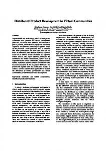
Let us come back to the main algorithm. Once the first hub-and-spoke cluster is mapped, the node nis should designate the next root (or root successor) in the substrate (with the maximum available capacity, i.e. Head(Ns )) to support the next hub-and-spoke cluster of the VN topology. Upon receiving a NEXT message (see S3), the new root node should firstly determine the set of neighboring spoke nodes already assigned to the substrate (i.e. the set A). Next, the hub-and-spoke procedure is called to map the spoke nodes which are not already assigned (i.e. Spokes except A). Finally, the algorithm computes the shortest paths between the root node and the spoke nodes already assigned to previous clusters. VII. I MPLEMENTATION AND P ERFORMANCE E VALUATION The Autonomic and Distributed Mapping Framework has been implemented and tested over the GRID5000 platform [15]. This platform can emulate a real substrate network where different topologies can be generated. An agent development framework [16] is used to implement the autonomous agents responsible for carrying out the distributed VN mapping algorithm. These agents are deployed in the GRID5000 machines to emulate the autonomic substrate nodes and to handle the VN mapping framework. A declarative Agent Communication Languages (ACLs) [17] is used to define and specify the interactions and messages between the autonomic substrate nodes. Our objective is to evaluate the distributed VN mapping algorithm performance in terms of time delay and number of messages required to map a given VN topology to a substrate network. The aim is to study the impact of the size and topology, of both substrate and virtual networks, on the distributed algorithm performance. A number of experiments have been set up to assess the proposed algorithm. To process a VN request, the Check-Root and SPT procedures require a considerable time delay due to the important number of messages exchanged between the agent-based substrate nodes. Our objective is, thus, to evaluate the performance of these two procedures in terms of time delay and message overload in the substrate network. A first experiment has been conceived to evaluate the Check-Root procedure. Several random substrate topologies with different sizes (from 0 up to 100 nodes) are generated over the GRID5000 platform. As shown in the figure 6, the response time remains below 1 s when the number of nodes is in the range from 0 to 80 and exhibits less variability on the average. Beyond 80 nodes, the Check-Root response time is more affected but is limited to a span of 1 to 2.7 s. Figure 7 depicts the number of messages exchanged between nodes that grows exponentially with increasing size of the substrate topology.
19
Fig. 6.
Check-root procedure evaluation: Time versus Nodes
Fig. 7.
Check-root procedure evaluation: Messages versus Nodes
The second experiment concerns the performance evaluation of the SPT procedure. The SPT procedure has been deployed in two types of substrate topology (Full Mesh Substrate (FMS) and Partial Mesh Substrate(PMS)). Figure 8 depicts two time delay curves. The lower and upper curves represent the time delay of the SPT procedure running on a partial mesh and a full mesh topology, respectively. Our major observation is that the additional delay between the two curves increases from 0 to 4.5 s when the number of nodes increases from 0 to 100. This additional delay is induced by the increasing number of messages illustrated in figure 9. A third experiment has been performed to determine the time delay taken by the distributed VN mapping algorithm to map different VN topologies (i.e. VN1 and VN2) to different substrate network topologies
20
Fig. 8.
SPT procedure evaluation: Time versus Nodes
Fig. 9.
SPT procedure evaluation: Messages versus Nodes
(e.g. FMS, PMS). VN1 topology is subdivided into 2 clusters (2 hub nodes and 12 spoke nodes), whereas VN2 topology is subdivided into 5 clusters (5 hub nodes and 4 spoke nodes). VN1 and VN2 have almost the same number of nodes with different topologies. As depicted in the figure 10, the time delay required to map VN2 (the upper curves) is higher compared to the time delay needed to map VN1 (the lower curves). This result shows that the time delay needed to map a VN topology depends on the number of clusters that compose the topology. Hence, the manner of subdividing a VN topology into clusters affects the time delay. The important number of messages illustrated in figure 11 and used to map a virtual network corroborates the delay results shown in the figure 10.
21
Fig. 10.
The time delay taken by the distributed algorithm to map different VN topologies
Fig. 11.
Number of messages used by the distributed algorithm to map different VN topologies
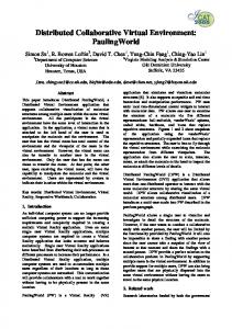
An other experiment has been conceived to evaluate the number of messages and time delay taken by the distributed algorithm to map different VN topologies (composed of 1, 2, 4 and 6 clusters) to different sizes of substrate network (i.e. 25, 50, 75 and 100 substrate nodes). In this experiment, the substrate has a PMS (Partial Mesh Substrate) topology and each VN cluster has one hub and three spoke nodes. As depicted in figure 12, the time delay required to map a VN topology increases quasi-linearly with the increasing number of substrate nodes. For instance, the time delay needed to map a VN topology composed of one hub-and-spoke cluster increases from 3.11 s to 11.48 s when the number of substrate nodes increases from 25 to 100. This delay is more noticeable in the case of mapping a VN topology composed of an important number of hub-and-spoke clusters (e.g. six hub-and-spoke clusters).
22
Fig. 12.
Time delay taken by the Distributed Algorithm to map different VN topologies with different number of clusters
Figure 12 shows also that the time delay required to map a VN topology in a substrate grows quasiexponentially when the number of VN clusters increases. For example, in the case of using a substrate with 25 nodes, the time delay needed to map a VN increases from 3.11 s to 18.27 s when the number of VN clusters increases from 1 to 6. This delay becomes quite considerable when the number of substrate nodes increases (e.g. 75 or 100 nodes). The increasing time delay required to map a VN topology is induced by the increasing number of messages (e.g. MSG, NOTIFY) exchanged between the autonomic substrate nodes. Figure 13 depicts the number of messages exchanged between nodes that grows with increasing size of the substrate topology. The important number of messages illustrated in figure 13 and used to map a virtual network corroborates the delay results shown in figure 12. Our major observation is that the time delay grows with increasing number of VN clusters. This result shows that the time delay needed to map a VN topology depends on the number of clusters that compose the topology, on the one hand, and the number of nodes constituting the substrate, on the other hand. As there are currently no known distributed VN provisioning algorithms available in the literature, at least to our knowledge, this paper is not in a position to provide any comparison with existing distributed VN mapping algorithms. VIII. C ONCLUSION This paper presented the design, implementation and evaluation of a distributed and autonomic virtual network mapping framework. The substrate nodes integrates autonomous and intelligent agents which
23
Fig. 13.
Number of messages used by the Distributed Algorithm to map different VN topologies with different number of clusters
exchange messages and cooperate to carry out the proposed VN mapping algorithm. A VN Mapping Protocol is used to communicate and exchange messages between the autonomic substrate nodes. Results from performance evaluation of the VN mapping framework suggest that the challenge of constructing virtual networks from a shared physical network can find viable solutions. The distributed and autonomic VN mapping framework presented in this paper can be a potential starting point for self-provisioning and self-management of virtual networks in a shared substrate and certainly a framework for further investigation. Future work will consist of implementing and evaluating more thoroughly the autonomic substrate node. Reasoning and learning mechanisms to ensure and provide intelligence to agent based substrate nodes will be added. Indeed, the intelligence of an agent element is very limited to its rule base and can not deal with unpredictable situations. Mechanisms like Collaborative Reinforcement Learning [18] should be used to provide intelligence and autonomic behaviors to agent based systems. The distributed and autonomic VN mapping framework presented in this paper can be a potential starting point for selfprovisioning and self-management of virtual networks in a shared substrate and certainly a framework for further investigation. R EFERENCES [1] Global Environment for Network Innovations (GENI). http://www.geni.net/. [2] Future Internet Network Design (FIND). http://find.isi.edu/. [3] T. Anderson, L. Peterson, S. Shenker, and J. Turner,. ”Overcoming the Internet impasse through virtualization”. IEEE Computer Magazine, vol. 38, no. 4, pp. 34-41, 2005.
24
[4] A. Bavier, N. Feamster, M. Huang, L. Peterson, and J. Rexford,. ”In VINI veritas: Realistic and controlled network experimentation”. in Proc. ACM SIGCOMM, Pisa, Italy, September 2006. [5] N. Feamster, L. Gao, and J. Rexford,. ”How to lease the Internet in your spare time”. SIGCOMM Comput. Commun. Rev., vol. 37, no. 1, pp. 61-64, 2007. [6] Y. Zhu and M. Ammar,. ”Algorithms for assigning substrate network resources to virtual network components”. in Proc. IEEE INFOCOM, 2006. [7] J. Fan and M. Ammar,. ”Dynamic topology configuration in service overlay networks: A study of reconfiguration policies”. in Proc. IEEE INFOCOM, 2006. [8] J. Lu and J. Turner,. ”Efficient mapping of virtual networks onto a shared substrate”. Washington University, Technical Report WUCSE2006-35, 2006. [9] M. Yu, Y. Yi, J. Rexford, and M. Chiang,. ”Rethinking virtual network embedding: Substrate support for path splitting and migration”. Princeton University, Technical Report TR-788-07, July 2007. [10] R. ricci, et al.,” A solver for the network testbed mapping problem ”, ACM Computer Communication Review, vol. 33, no. 2, pp. 65-81, January 2003. [11] P. Horn, ”Autonomic Computing: IBM’s perspective on the State of Information Technology”, IBM Corporation, Online reference, www.research.ibm.com/autonomic/, Oct 2001. [12] R. Bellman, ”Dynamic Programming”. Princeton, N.J.: Princeton Univ. Press, 1957. [13] G. Tesauro , et al.,” A multi-agent systems approach to autonomic computing ”, Third International Joint Conference on Autonomous Agents and Multi Agent Systems, 2004, p. 464-471. [14] S. Bandini, et al. ”Mechanisms to Support Situated Agent Systems”, 7th IEEE Symposyum on Computers and Communication, Italy, 2002. [15] GRID 5000, https://www.grid5000.fr/ [16] JADE (Java Agent DEvelopment Framework), http://jade.tilab.com/ [17] FIPA (FOUNDATION FOR INTELLIGENT PHYSICAL AGENTS), http://www.fipa.org/. [18] J. Dowling , et al.,” Building autonomic systems using collaborative reinforcement learning ”, The Knowledge Engineering Review, vol. 21, no. 3, pp. 231-238, September 2006.