This full text paper was peer reviewed at the direction of IEEE Communications Society subject matter experts for publication in the IEEE GLOBECOM 2005 proceedings.
Virtual Network based Autonomic Network Resource Control and Management System Myung Sup Kim, Ali Tizghadam, Alberto Leon-Garcia Dept. of Electrical and Computer Engineering University of Toronto Toronto, ON, M5S1A4, Canada
James Won-Ki Hong Dept. of Computer Science and Engineering POSTECH Pohang, Gyungbuk, 790-784, Korea
{myungsup.kim, ali.tizghadam, alberto.leongarcia}@utoronto.ca
[email protected]
Abstract— Traditional telecommunications service providers are undergoing a transition to a shared infrastructure in which multiple services will be delivered by peer and server computers interconnected by IP networks. IP transport networks that can transfer packets according to differentiated levels of QoS, availability and price are a key element to generating revenue through a rich offering of services. Automated service and network management are essential to creating and maintaining a flexible and agile service delivery infrastructure that also has much lower operations expense than existing systems. In this paper we focus on the SLA-based IP packet transport service on a core network infrastructure and we argue that the above requirements can be met by a self-management system based on autonomic computing and virtual network concepts. We present a control and management system based on this approach. Keywords-Autonomic Computing; Virtual Network; SLA; Resource Management
I.
INTRODUCTION
Traditional telecommunications service providers are undergoing a transition to a shared infrastructure in which multiple services and applications will be delivered by peer and server computers interconnected by IP networks. IP/MPLS transport networks that can transfer packets according to differentiated levels of QoS, availability and price are a key element to generating revenue through a rich offering of services and applications. In this environment, Network Service Providers (NSPs) must address the challenge of how to deliver SLA-based network service to large customers. For example, a “customer” could be the Voice-over-IP (VoIP) organization of a service provider which requires that its aggregate flows be handled by the IP transport network according to specified delay, jitter, loss, and availability metrics. Another “customer” may be a third-party VoIP provider that purchases the packet transfer service. Clearly other service and applications can generate large customers, e.g., IPTV, VPNs. Virtual network based resource management is necessary and sufficient to guarantee the customer’s diverse traffic demand [1, 2]. The customers’ traffic must share the same physical core network infrastructure. The service provider should handle these traffics with different policies to meet each of their SLA requirements. Each customer’s traffic consists of
IEEE Globecom 2005
multipoint-to-multipoint flows that require a certain amount of network resources. Virtual network partitioning of network resources provides an approach to ensuring that the SLA requirements of large customers are met. A virtual network (VN) consists of sufficient network resources that are allocated to a customer to accommodate its flows and meet its SLA [3, 4]. Automated service and network management is essential to creating and maintaining a flexible and agile service delivery infrastructure that achieves much lower operations expense than existing systems. Autonomic computing as defined in [5, 6] is a natural approach to IP network resource management. Autonomic computing can address the delivery of multiple services with different SLAs using a shared set of computing resources. Effectiveness in service delivery is achieved by assigning to each service an autonomic manager that ensures that the service is delivered according to the prescribed SLA. The manager monitors and analyzes resource state and service metrics, and plans and executes appropriate actions to ensure that service metrics are met in the presence of faults and a changing environment. In the context of an SLA-based IP transport service, an autonomic manager is created for each virtual network. The VN approach to network resource management is not new [3, 4]. The combining the VN concept and autonomic computing, however, brings greater clarity to the methodology of designing future management systems that must attain greater degrees of scalability and manage higher levels of application diversity and adaptivity than required by networks in the past. In addition, with the focus of application delivery shifting to the peer/server computing infrastructure, it is our belief that future network management systems, to the extent possible, should incorporate resource management methodologies developed for information technology. The organization of this paper is as follows. Section 2 describes the features of the SLA-based core network service and analyzes the requirements of this service in the perspective of customers and service provider. Based on the requirement analysis we developed a VN-based autonomic network resource control and management system named VNARMS. In section 3, we propose an overall architecture of VNARMS and describe the relationship among autonomic managers in VNARMS. Section 4 addresses the detailed design issues of
1075
0-7803-9415-1/05/$20.00 © 2005 IEEE
This full text paper was peer reviewed at the direction of IEEE Communications Society subject matter experts for publication in the IEEE GLOBECOM 2005 proceedings.
our proposed system. In section 5, we conclude this paper with current status of our research and scheduled future work. II.
REQUIREMENTS FOR SLA-BASED NETWORK SERVICE
In this section, we consider requirements on the SLA-based network service from the perspective of the customers and the service provider. Based on this requirement analysis we design an autonomic network resource management system. The customers can be an enterprise, a content service provider (CSP), a third party network reseller like a VPN provider, and application service providers, e.g. VoIP or IPTV. The network service provider (NSP) owns and operates the physical core network resources. The service instance delivered from the NSP to a customer is a virtual network (VN). The virtual network (VN) is an abstraction of a physical network that consists of a partition of network resources. A. Customer Requirements First, the customer requires the creation of a VN that can deliver a certain level of quality. The metric of VN quality can be end-to-end bandwidth and delay for multiple routes. When a customer negotiates the SLA for a VN, the VN topology may or may not be specified. Second, the customer wishes to monitor the current and historical status of his VN at various times. This VN usage data allows the customer to anticipate future VN usage and to plan for improved utilization. Third, the customer may wish to reconfigure the contracted VN capacity or to remove the VN. Fourth, the customer may choose to create one or more new VNs within its own VN capacity boundary and to resell these to other customers. This reselling activity should be performed independently from the NSP. Fifth, a VN control and management system should be provided to the customer when a new VN is created. Starting from the physical network infrastructure, a multi-level recursive creation of VNs and associated control and management system should be supported. B. Service Provider Requirements First, every service provider attempts to optimize the use of its resources (whether physical or virtual) to maximize its service revenue. In this general sense, the NSP that owns the physical network resources has the “root-VN” from which other VNs can be spawned. The VN customer in turn can be a service provider to other customers. Second, the operation expense of a VN should be minimized by automatically and efficiently carrying out the customer or service provider requests. The automatic configuration of VN is very important to reduce network operator errors which are the cause for a significant amount of misuses and faults. Third, the system should provide an autonomic way to handle fault and overload conditions on each VN and on its virtual network resources (VNR). For this autonomic operation, the system should have pre-defined autonomic routines to determine, isolate, and repair faults according to policy. Fourth, the service provider may wish to provide VN services with different levels of availability (such as 99.999% of availability) to different customers. For this goal, the system should provide appropriate levels of resource redundancy and appropriately fast fault recovery
IEEE Globecom 2005
mechanisms. Fifth, when a new VN is created, the system should select an optimal topology, link bandwidths and call admission control mechanism. Finally, the ultimate goal of the NSP is to maximize its revenue, and to do so, it must decide on the optimal mix of services and prices it should offer to its customers based on the available infrastructure and the forecasted demand. III.
OVERALL SYSTEM ARCHITECTURE
We now describe the overall architecture of VN-based autonomic network resource control and management system (VNARMS). The virtual network and autonomic computing concepts are applied to this architecture to make the service provisioning and operation efficient, scalable and costeffective. A. Service Life Cycle and Autonomic Computing Figure 1 illustrates a general service life cycle, which has four subsequent stages: service creation, service activation, service maintenance, and service extinction. Service Service Creation Creation
Service Service Activation Activation
Service Service Maintenance Maintenance
Service Service Extinction Extinction
1. Service Definition 2. Requirement Analysis 3. System Analysis 4. System Design 5. Implementation 6. Testing 7. Deployment
1. Service Sales 2. SLA Negotiation 3. Service Provisioning 4. Service Renegotiation 5. Service Termination
1. Service Monitoring 2. Performance Analysis 3. Fault Detection 4. Fault Recovery 5. Customer Billing
1. No customer exist 2. No service revenue
Autonomic System Design
Autonomic System Control & Management
Figure 1. Service Life Cycle
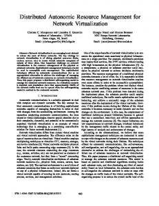
The autonomic service provisioning system should carry out the tasks in the stage of the service activation and service maintenance in an autonomic manner. For the autonomic process, the service control and management system should be developed with the autonomic concept in the service creation stage. Therefore, the service provider should consider the autonomic control and management when it develops a new service. With this philosophy, we developed the VNARMS. B. Overall Architecture of VNARMS Figure 2 illustrates a high-level overall architecture of VNARMS and the interactions with external components (customers, service providers, and physical network resources). We assume that the physical network is the IP-MPLS network with DiffServ capability, although the operation of VNARMS is not strictly dedicated to the IP-MPLS networks. The VNARMS provides VN to customers according to the service provider’s policy and customer’s quality demand. A customer provided a VN by a service provider, in turn, could be a new service provider that sells some portion of its VN to another customer by VN spawning process. This recursive VN spawning process is one of the key features of our VNARMS system along with the autonomic features, which gives the network re-sellers or service organizers flexibility and controllability in operating their VNs. The VNARMS has two types of autonomic components: the virtual network resource manager (VNRM) and the resource agent (RA). The VNRM is responsible for the VNlevel control and management, while the RA is responsible for
1076
0-7803-9415-1/05/$20.00 © 2005 IEEE
This full text paper was peer reviewed at the direction of IEEE Communications Society subject matter experts for publication in the IEEE GLOBECOM 2005 proceedings.
the element-level resource control and management. In a single VN topology, each switching resource is controlled by one RA. Multiple VNRMs can exist in our VNARMS in a hierarchical structure like that of the VNs. If there are ten VNs created on a physical core network, there should be ten VNRMs, each of which controls one VN assigned to it. There is no interaction among RAs in a single VN. The RAs in different VNs run independently with little interaction, because, when a new VN is spawned from a parent VN, the parent RA creates a child RA when the parent VNRM creates the child VNRM. VNARMS RA2
VNRM3 VNRM5
Customer Customer
Request Response
RA4 RA6
VNRM4 VNRM2
RA5
Control Report
Service Service Provider Provider
RA3
VNRM1
VNRM2 and RA3 spawn VNRM3 and RA5, respectively, after they create VN3. The recursive spawning of VNRMs and RAs, allows the customer of a VN to have controllability to its own VN, independently of other VNs and customers. Furthermore, this hierarchical processing of VNs provides scalability and extendibility. All VNRMs and RAs are autonomic managers. The autonomic manager handles requests or notifications from external components in an autonomic way. A VNRM communicates with its parent VNRM, its child VNRMs, its owner service provider, customers, and its RAs. For example, the VNRM2 in Figure 3 receives requests or notifications from VNRM1, VNRM2, CSP, CS, RA3 and RA4. The contents of external requests are listed in TABLE 1, which is not exhaustive but important.
RA1
SP Edge Router
CSP
CS
Informational Model
Control
Monitor
VN 3 spawning
Core Router
Core Router
VN 2
Edge Router
IP-MPLS Core Network
Network Management Layer
VNRM1 VNRM1
Element Management Layer
RA1 RA1
VNRM2 VNRM2
spawning
VNRM3 VNRM3
VN 1
Figure 2. Overall Architecture of VNARMS
The VNRM and RA are the autonomic managers that are arranged according to the autonomic control loop structure: monitor, analyze, plan, and execute [5, 6]. By monitoring their target managed objects, the autonomic managers diagnose the object’s status. The managed objects of the VNRM and RA are the RAs and physical network elements, respectively. When a problem is determined, first, the manager tries to localize the problem and repair it by itself. Depending on the nature of the problem this may result in self-healing (in case of an error) or self-organizing (re-arrange the resources to attain optimum utilization) or self-configuring (adapt to the other changes). If the manager cannot handle the problem, the high-level autonomic manager is involved. Through this hierarchical autonomic problem handling, a hierarchical autonomic manager structure can manage and control large core networks. C. Relationship among VNRMs and RAs Figure 3 illustrates an example of VN spawning operation and the relationship among VNRMs and RAs. The informational model in Figure 3 shows that the VN1 spawns the VN2 and the VN2 in turn spawns VN3. The ownership of VN1, VN2, and VN3 is to the SP, CSP, and CS, respectively. Initially, the SP controls VN1 through the VNRM1, RA1 and RA2. In this example, there are two network elements which can be routers or switches in a core network. When CSP wants a VN (VN2 in this example) it contacts VNRM1 and requests a new VN creation with a given SLA. After receiving a VN creation request, the VNRM1 calculates an optimal VN topology and effective bandwidth for each end-to-end route on this topology to create a new VN for the CSP. After creating VN2 for the CSP, the VNRM1 and its RAs (RA1 and RA2) perform additional actions to provide the CSP with the controllability of VN2. VNRM1 creates VNRM2, and RA1 and RA2 spawn RA3 and RA4, respectively. With the newly created VNRM2, RA2, and RA4, the CSP can control its own VN2. Similarly, CS contacts VNRM2 to create a new VN.
IEEE Globecom 2005
RA2 RA2
RA4 RA4 RA3 RA3
NE 1
RA5 RA5
NE 2
Figure 3. VN spawning operation
In case of RAs, the external components that generate requests or notifications are the VNRM, the parent RA and the physical network element. For example, RA 3 in Figure 3 receives the requests and notifications from VNRM2, RA1, and the physical element 1. From
To
Operation
SP
VNRM
VN policy setup request, VN reconfiguration request, VN removal request
CS
VNRM
CS subscription, CS SLA negotiation, Child VN creation request, Child VN reconfiguration, Child VN removal
Parent_VNRM
VNRM
VNRM creation, VN status notification
Child_VNRM
VNRM
Child VN reconfiguration request, Child VN removal request
RA
VNRM
VNR status notification
VNRM
RA
RA policy setup, VNR partitioning request. VNR reconfiguration request, VNR removal request, VNR monitoring request
Parent RA
RA
RA creation, VNR status notification
Physical NE
RA
NE status notification
TABLE 1. Requests from external components to VNRM and RA
The high-level policy from a service provider is deployed automatically through the hierarchical autonomic manager structure and each autonomic manager configures itself based on the given policy (self-configuring) and processes requests from external components based on the policy. This minimizes human intervention and leads to cost effective operation. Each autonomic manager tries to optimize its corresponding managed objects by forecasting future demand based on policy. As indicated above, this hierarchical structure makes the system very scalable. The system can also adapt to the changes in network topology by adding new management components in the resource and network management layer.
1077
0-7803-9415-1/05/$20.00 © 2005 IEEE
This full text paper was peer reviewed at the direction of IEEE Communications Society subject matter experts for publication in the IEEE GLOBECOM 2005 proceedings.
IV.
DETAILED ARCHITECTURE OF VNARMS
We now present the detailed architecture of VNRM and RA, the two types of autonomic managers in the VNARMS. We describe the functional building blocks of the VNRM and RA and show an example of autonomic operation of VNARMS. A. Autonomic Manager Functional Blocks First, we define generic functional building blocks for an autonomic manager as an extension of the IBM autonomic manager structure [6]. To achieve complete autonomic computing for a service, the four parts of the Figure 4 should be executed automatically in each autonomic manager: customer control, policy control, service activation, and service maintenance. These four parts are tightly coupled and communicate to each other to achieve the ultimate goal: selfmanagement of a service. This concept can be applied to all kinds of services, including application-layer services and network-layer services. Customer Customer Business Management Layer
Service / Network Management Layer
Customer Control
Resource / Element Management Layer
SP
Parent VNRM
Policy Setup VN config.
Request Manager
VN Status Notification
Policy Manager
VN re-config. request
Accounting Manager Billing info.
Policy Information Base (PIB)
Child VN config. request Child VN re-config. req.
VN Manager
VNR config. info.
Child VN creation Child VN status notification
Customer Information Base (CIB)
Operation Manager
Child VN topology info.
Topology Manager
Resource Manager RA config.
VN Information Base (VNIB)
VNR status info. RA status notification
VN config. request
AM
Service Maintenance
- Service monitoring - Performance Analysis - Problem Detection - Problem Recovery
Sensors Anal yze
Effectors
Moni tor Kn owledg e
Sensors
Child VNRM
Plan
RA
RA
Parent VNRM
Figure 5. Detailed Functional Architecture of VNRM
Execu te
Effectors
Focus of IBM Autonomic Control Loop
Resources Resources
Figure 4. The functional building blocks of an autonomic manager
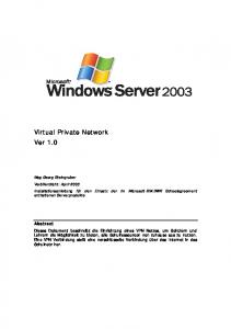
The service provider uses the policy control building block to set up policy for the other three functional building blocks. The customer control building block is in charge of the interaction with customers. The customer contacts the system through the customer control block and negotiates the service quality. Based on the SLA information, the service activation building block creates a new service instance for the customer. The service maintenance building block controls and manages the resources during the lifetime of each service instance (problem detection, problem recovery, etc). The maintenance outcomes are sent to the customer control for customer care functionality, such as billing. There is some functional overlap among these parts. For example, the service planning to find optimal resource allocation could be processed in the service activation and service maintenance building blocks. The IBM autonomic control loop architecture [6] mainly concentrates on the service maintenance part of the Figure 4, and gives less attention to the interactions with a service provider and customers of the autonomic system. Also, the deployment of services and the creation of new service instances are not considered. B. Detailed architecture of VNRM Figure 5 illustrates the detailed ten functional building blocks of the VNRM. The VNRM has three different
IEEE Globecom 2005
Child VNRM
Child VN Child VN config. request config. request
- Policy Setup - Policy validation - Policy Translation - Policy Distribution
Knowledge Base
- Service Creation - Service Config. - Service Planning - Plan Execution
Customer
Service Service Provider Provider
Policy Control
- Customer Contract - SLA negotiation - Customer Billing - SLA translation
Service Activation
knowledge bases: PIB, CIB, and VNIB, which store static and dynamic information about policy, customer, and VN, respectively. The Policy Manager is responsible for policy translation, policy distribution, and policy validation. It receives the SP’s policy and translates it into VN and VNR policy. The VN policy is stored in the PIB and VNR policy is distributed to all RAs through the Resource Manager. The policy for autonomic manager is one of our and others ongoing research investigations [7]. In addition to the policy operation, the Policy Manager handles all other requests from the service provider, e.g. VN reconfiguration and VN removal requests. The Request Manager, on the other hand, handles all the requests from customers.
The Request Manager is responsible for customer contact and SLA negotiation. To create a new VN, a customer should subscribe itself to the VNRM and specify VN quality requirements through the Request Manager. SLA metric for VN creation and reconfiguration is also a part of our on-going investigation. The Request Manager also validates the customer VN requirements based on the pre-defined policy and its current VN status, and if appropriate it sends a VN create request to the VN Manager. The VN Manager is responsible for the creation, modification, and removal of child VNs. On reception of a VN creation request, the VN Manager makes a topology request to the Topology Manager to find an appropriate VN topology. The VN Manager then makes a resource reservation request to the Resource Manager. In addition, the VN Manager handles the VN re-configuration and removal request from the Request Manager and the child VNRM. The VN Topology Manager is responsible for creating a set of optimal routes and calculating the corresponding effective bandwidth when a new VN is created, or when a VN is reconfigured. Much research [8, 9, 10] has been devoted to route-level QoS, but extensions are required for VN-level QoS guarantees. The goal of VN manager is to find optimal VN allocation from the given network resources that maximize the resource utilization and service revenue, another area of on-going research. The Resource Manager is responsible for the communication between the VNRM and the RAs. It translates the VN spawning message into a VNR partitioning message and distributes it to the corresponding RAs to create a new VN. It also sends monitoring requests to the RAs and receives status
1078
0-7803-9415-1/05/$20.00 © 2005 IEEE
This full text paper was peer reviewed at the direction of IEEE Communications Society subject matter experts for publication in the IEEE GLOBECOM 2005 proceedings.
information from them. The Operation Manager is responsible for the analysis of each child VN and the overall VN status. It determines VN level problems and sends a VN reconfiguration message to the VN Manager. In addition, it handles the SLA monitoring. The SLA analysis result is stored in the CIB, which is used for customer billing by the Accounting Manager. The VNRM implements the autonomic control loop that involves the four main components: Resource Manager, Operation Manager, VN Manager, and Topology Manager. The Resource Manager does monitoring; the Operation Manager does monitoring and analysis; the VN Manager and Topology Managers do planning; and the Resource Manager performs execution. Furthermore, the seven functional components follow the four autonomic functional components described in Figure 4. C. Detailed architecture of RA The RA is composed of six functional building blocks, as illustrated in Figure 6, which interact with each other based on RA policy. The Request Controller receives VNR partitioning/reconfiguration requests and sends them to the VNR Controller after validating the request. In addition, the Request Controller handles the RA policy setup request from the VNRM. The Request Controller is in charge of customer control and policy control in the autonomic functional building block in Figure 4. The VNR Controller plans the operation of each virtual resource for incoming traffic. For example, the methods of call admission control at edge routers and alternative route selection at edge and core routers in case of congestion are decided and optimized in the VNR Controller. Furthermore, the VNR Controller creates a new RA when a new VNR is created for a new VN and it sends VNR modification alarm reports to a child RA when its VNR status has changed. The Operation Controller determines VNR level problems and tries to fix them before sending alarms to the VNRM. The VNR status data is delivered from the Resource Controller of the same RA and the VNR controller of the parent RA. The Resource Controller is responsible for the control of physical network equipment. The serialization of operations from multiple RAs is another on-going investigation. Child RA
VNRM
RA/VNR policy VNR configuration
Parent RA VNR status info. to a VNRM
Child VNR status info. to child RA
Request Controller
VNR Controller
VNR request (creation/re-configuration/removal)
Resource Controller
VNR Re-config. request
VNR status info. notification
Policy Information Base (PIB) Operation Controller VNR Information Base (VNRIB)
VNR configuration request
VNR status info.
Physical NE
Figure 6. Detailed Functional Architecture of RA
The Resource Controller, Operation Controller, and VNR Controller form the main autonomic control loop in the RA. The RA periodically retrieves status data of the VNR through
IEEE Globecom 2005
the Resource Controller. When any fault is detected the Operation Controller tries to resolve the problem through the VNR controller. The Operation Controller coordinates the sequence of VNR recovery when more than one VNR are in an unstable state. The VNR Controller finds the optimal solution for the given problem based on the VNR policy and configures the physical network device through the Resource Controller. If the problem cannot be resolved by RA itself, the Operation Controller sends an alarm notification to the corresponding VNRM. V.
CONCLUDING REMARKS
In this paper we presented requirements for SLA-based IP packet network service on a core network infrastructure, and we proposed a virtual network based autonomic network resource control and management system architecture. We argue that the VN-level QoS guarantee as well as link- or route-level QoS guarantees should be considered to meet customer various traffic demands on core network environments. In addition, providing a customer with the controllability for his virtual network is an important element to increase the service flexibility. This paper focused on the description of the architecture and operation of our proposed autonomic system. This is a work in progress and many issues remain to be addressed including adaptive algorithm development, system dynamics characterization, performance evaluation, and implementation of a proof-of-concept system. REFERENCES [1]
Andrew Do-Sung Jun and Alberto Leon-Garcia, “Virtual network resources management: a divide-and-conquer approach for the control of future networks,” Proc. of Globecom'98, Sydney, Australia, Vol. 2, Nov. 1998, pp. 1065-1070. [2] Raouf Boutaba, W. Ng, and Alberto Leon-Garcia, “Web-based customer management of virtual private networks,” Journal of Network and Systems Management, Vol. 9 No. 1, Mar. 2001, pp. 67-87. [3] A. Leon-Garcia and L. Mason, “Virtual network resource management for next-generation networks,” IEEE Communications Magazine, Vol. 41, No. 7, Jul. 2003, pp. 102-109. [4] G. Woodruff, N. Perinpanathan, F. Chang, P. Appanna, and A. LeonGarcia, “ATM network resources management using layer and virtual network concepts,” IM '97, May 1997. [5] Jeffrey O. Kephart and David M. Chess, “The vision of autonomic computing,” IEEE Computer Magazine, Vol. 36, No. 1, Jan. 2003, pp. 41-50. [6] IBM White Paper, “An architectural blueprint for autonomic computing,” Apr. 2003. [7] K. Appleby, S. B. Calo, J. R. Giles, and K.-W. Lee, “Policy-based automated provisioning,” IBM Systems Journal, Vol. 43, No. 1, 2004, pp 121-135. [8] Panos Trimintzios, David Griffin, Panos Georgatsos, Danny Goderis ,Yves T’Joens, Leonidas Georgiadis, Christian Jacquenet, and Richard Egan, “A management and control architecture for providing IP differentiated services in MPLS-based networks,” IEEE Communications Magazine, Vol. 39, No. 5, May 2001, pp. 80-88. [9] E. Bouillet, D. Mitra, and K. G. Ramakrishnan, “The structure and management of service level agreements in networks,” IEEE JSAC, Vol. 20, No. 4, May 2002, pp. 691-699. [10] E. C. Rosen and Yakov Rekhter, “BGP/MPLS IP VPNs,” IETF Internet Draft, draft-ietf-l3vpn-rfc2547bis-03.txt, Oct. 2004.
1079
0-7803-9415-1/05/$20.00 © 2005 IEEE