A Distributed Architecture for a Ubiquitous Item Identification Network Damith Chinthana Ranasinghe1, Kin Seong Leong1, Mun Leng Ng1, Daniel Engels2, Peter Harold Cole1 1
Auto-ID Labs, School of Electrical and Electronic Engineering, University of Adelaide, SA 5005, Australia {damith,kleong,mng,cole}@eleceng.adelaide.edu.au 2 Auto-ID Labs, Massachusetts Institute of Technology 77 Massachusetts Avenue, NE-46, Cambridge, MA 02139 USA
[email protected]
Abstract. The concept of a “Networked Physical World” originated from the Auto-ID Center, now called the Auto-ID Labs. Such a system can be realized with a combination of automatic identification technology and a ubiquitous computer network that will glue the physical world together. The ability to form a ubiquitous item identification network has a wide range of applications including manufacturing automation and supply chain management. We describe the building block system components of a distributed ubiquitous item identification network aimed at creating a “Networked Physical World” system and explore the data flows within the system.
1 Introduction Originally the architecture to build a ubiquitous item identification network commenced at the former Auto-ID Center, now the Auto-ID Labs [1] with the process of standardization issues currently managed by EPCglobal Inc [2]. The Auto-ID Center’s vision was to create a “Smart World” by building an intelligent infrastructure linking objects, information, and people through computer networks oblivious to the users. The creation of the intelligent infrastructure demanded the ability to identify objects automatically and uniquely with the backbone of the infrastructure provided by a ubiquitous computing system leveraging the internet for global connectivity. The components forming the intelligent infrastructure are commonly referred to as an EPC Network where the term EPC (Electronic Product Code) is a result of the unique object identification scheme employed by the system. This new infrastructure enables object-centric computing that will allow universal coordination of physical resources through remote monitoring and control by both humans and machines. While the applications of this technology are widespread the EPC Network is expected to revolutionize supply chain management. The EPC Network is assembled upon many building blocks representing a number of fundamental technologies and standards. We present the system components and
technologies of the ubiquitous item identification network (EPC Network) in the first section and provide architecture for extending the local area EPC Networks with an outline of the data flow within such a network.
2 EPC Network Tags Reader Tags
Network infrastructure Reader
Tags
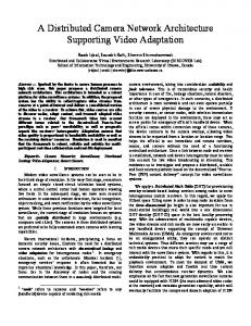
Fig. 1. An Overview of an EPC Network. The arrows indicate the flow of data from tags to network support system and the flow of control and data back to the readers and tags.
The network of physical objects is achieved by integrating an electronic Radio Frequency Identification (RFID) transponder (RFID label) into each object. The system networks objects seamlessly by communicating with these labels at suitably placed locations: portals, mobile locations, through handheld devices, and potentially, eventually for some tags, continuously throughout the environment. A network of RFID readers are used to collect data from tagged objects. The RFID labeled objects communicate an EPC code to identify themselves as a unique entity. The data originating from the network of readers is passed to a control and data collection systems that provide service layer functionalities. An illustration of the components constituting the EPC Network is shown in Figure 1. ONS
EPC Information Service (EPC Database)
ALE Engine
Reader
Tags
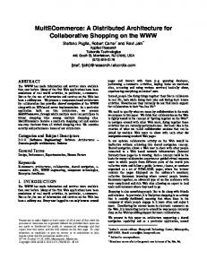
Fig. 2. The component based structure of a local area EPC Network.
EPC Networks are significantly different from more traditional computer networks in the sense that the flow of data and information is from many nodes (RFID tags) at the edge of the network towards a number of central servers. In RFID networks, Readers detect certain events or Readers query RFID labels to obtain event data and forward the resulting information to backend applications or servers. The application systems then respond to these events and application processes orchestrate corresponding actions; such as ordering additional products, sending theft alerts, raising alarms regarding harmful chemicals or replacing fragile components before failure.
The EPC Network is a component based architecture with six primary components, some physical, some, logical: (1) RFID tags, (2) RFID tag readers (interrogators) (3) Electronic Product Code (EPC), (4) the Application Level Event (ALE) Engine systems, (5) Object Name Service (ONS), and (6) EPC Information Service (EPCIS). Figure 2 shows the structure of a typical EPC Network where Readers communicate with tags and then capture that information to be passed up the information chain to be utilized by the service layers for various applications. ONS Local EPC Network
Local EPC Network
Local EPC Network
INTERNET
Local EPC Network
Local EPC Network
Fig. 3. Wide area EPC Network overview. The local EPC networks are able to route their information and requests to remote and unknown locations using the translation services provided by a network of global public ONS servers.
The EPC Network shown in Figure 2 is a local area EPC Network akin to LANs. This model captures the architecture of the system at a local site; company or organization, or a private network. Nonetheless, local EPC Networks can be linked together through the already established backbone of the Internet to achieve a global flow of information and data to extend the outreach and the usefulness of the EPC Network. Figure 3 illustrates such architecture where a global public ONS system may be used to connect public local area EPC Networks. The subject of ONS is considered in Section 5 of the paper.
3 RFID Components The RFID aspects of the EPC Network consist of RFID tags (the miniature computing devices forming an interface to the objects) and RFID readers. The following is an overview of the RFID components of the EPC Network while a more complete and thorough coverage of the topic may be obtained from [2 and 3]. RFID tags, when coupled to a reader network, form the link between physical objects and the virtual world in the EPC Network. RFID tags have a small radio antenna that transmits information over a short range to an RFID tag reader [3]. RFID technology may use both powered and non-powered means to activate the electronic tags. Powered devices use batteries to actively transmit data from the tags to more distant readers. Electronic highway toll systems are good examples of active RFID tags. Passive RFID devices literally harvest energy from the electromagnetic field of an active reader to both power the tag and transmit the data. Modern RFID labels are fabricated using standard CMOS technology and are interrogated by the process of RF backscatter [4]. In the most cost effective and popular technology, the tags are passive and in consequence the ranges of operation are limited (few meters) [5].
Network infrastructure
Controller
Passive systems are well suited for use in the EPC Network due to their low cost, but the architecture of the network does not place a restriction on the tags that can be employed as tags with substantially enhanced functionality (such as sensors) will extend the depth of the application layer. A simple illustration of the concept of a Radio Frequency Identification (RFID) systems used in the EPC Network are shown in Figure 4. Currently there are standardization efforts to produce a harmonious air interface for low cost RFID tag that requires a minimum of functionality implemented on the microchip. However there are existing protocols for an RFID air interface in the ISO standards (ISO 18000). Due to the cost constraints of tagging a quadrillion objects, it is expected that the majority of tags integrated with physical objects will be passive tags. Transmitter
Receiver Labels
Fig. 4. RFID System overview. The transmitter, Receiver, and the Controller forms the RFID reader. Here a transmitter of interrogation signals which is contained within a reader communicates via electromagnetic waves with an electronically coded label to elicit from the label a reply signal containing useful data characteristic of the object to which the label is attached. The reply signal is detected by a receiver in the interrogator and made available to a control system.
A ubiquitous reader network will allow continuous tracking and identification of physical objects. Reader arrays can be fabricated and integrated in floor tiles, carpeting, shelf structures, cabinets and appliances. Similarly to cellular phone grids, the reader network may provide seamless and continuous communication to tagged objects. A data collection and control system must support the reader network to enable efficient use of the continuous, or at least very frequent, object communications. Additionally, in order to access and identify these objects, a scheme is required to uniquely name and identify objects.
3.1 Unique object identifier MSB Header
General Manager number
Object Class
LSB Serial number
Fig. 5. Bit level representation of an EPC general type identifier format. Header identifies the EPC format used by the tag; 96-bit, 64-bit or 256-bit. General Manager Number identifies an organizational entity. These numbers need to be unique and can be assigned by a standards body such as EPCglobal Inc. while Object Class is used by a General Manager to identify a specific product class. The Serial Number is a unique number within each Object Class
The unique object identifier must have a global scope that is capable of identifying all objects uniquely and act as a pointer to information stored about the object somewhere over the network. The Electronic Product Code (EPC) is a scheme designed for universal object identification with the associated standards developed by EP-
Cglobal Inc. A binary representation of the EPC is shown in Figure 5 [6]. It is important for serial numbers to be unique for objects labeled by a particular organization within a product class. However, different objects may reuse the same serial numbers, as the difference in product codes will ensure unique identification of the product. Hence, the triplet of General Manager Number, Object Class, and Serial Number uniquely identifies an object.
4 Application Level Event (ALE) Engine ALE Engine system is a middleware system between a reader (or multiple readers) and the applications systems (Figure 6). Networked ALE Engine systems form a framework to manage and react to events generated by tag reads by interrogators. The ALE Engine passes requests from the applications to the reader(s) and receives unique tag identifiers and possibly other data from sensors, and passes that information to the applications EPCIS
Application Systems
Application Systems
Application Level Event Interface ALE ENGINE SERVICES ALE Service
ALE Service
ALE Service
ALE Service
ALE Engine
Reader Protocol Interface Reader
Reader
Reader
Fig. 6. Architecture of a ALE Engine System and its interaction with EPC Network components; EPCIS and other Application Systems and Readers
The ALE Engine has several fundamental functions integrated into its design where event management (an event is an interaction with a reader resulting in obtaining a number of EPC data) is a primary function which involves data filtering, aggregation and counting of tag data. These functions are required to handle the potentially large quantities of data that RFID systems are capable of generating through continuous interrogation of tags. For example, readers may read data coming in from multiple RFID tags, repeatedly. Not all of the data from all of the tags may be of interest to the application. Filtering of that data can eliminate information, that is either redundant (multiple reads of the same data) or that is not required (tags read but not of interest to that application), from reaching the specific application. An ALE engine may be configured to report the captured information, as requested by an application in a periodic manner or asynchronously as events occur over time. The ALE Engine consists of two primary interfaces that allow it to communicate with external systems: the Reader Protocol Interface and the Application Level Event Interface. The former provides and interface between the ALE Engine and readers, and the latter between the ALE Engine and external applications [7]. ALE Engine is
composed of multiple ALE Engine Services each of which has its own functionality. These modules can be combined to perform certain functions for specific applications. Other than ALE Engine Services interacting with each other to perform certain tasks, ALE Engine Services can also interact with external services such as the EPC Information Service (EPCIS) and provide services for other local applications. Figure 6 shows the basic architecture of the ALE Engine system.
4.1 EPC Data Encapsulation and Reporting The EPC serves as a reference to information however the storage, transport and description of that information requires a structured and universal body that can be easily understood, stored and transported across the internet. Previously the Auto-ID Center defined the Physical Markup Language (PML) (PML Core specification 1.0, Sept. 2003) to encode captured object information. However recent developments have retreated from such a rigid definition to the characterization of two instances: ECSpec and ECReports instances using a standard XML depiction. Thus requests to the ALE Engine are sent as an ECSpec object while data from the ALE Engine is returned as an ECReports object. The XML schema for these objects are defined with extensions to accommodate application or manufacture specific XML schema (such as that suited for a specific sensor application) or a number of such schemas to allow the capture and reporting of physical world events and measurements. The core XML schema is tailored specifically to describe common attributes of physical objects and observables, such as the expiry date, manufacture date, weight, or the time an object was seen at location X. XML promises a universal means for encoding structured information while the core XML schema is rigid, simple and use elements that can be understood easily because the definition uses long descriptive tags.
5 Object Name Service The functionality provided by the ONS system is similar to that provided by the Domain Name System (DNS), however instead of translating host names to their underlying IP addresses for user applications, ONS translates an EPC into a URL(s). The Object Name Service (ONS) identify the location of the server hosting the appropriate information needed by an application. The ONS functions like a “reverse phone directory” since the ONS use a number (EPC) to retrieve the location of EPC data from its databases. In order to encourage rapid development of the ONS, the ONS is based on existing DNS systems. Figure 7 shows the overview of an ONS system. The ONS needs to resolve to a greater depth than an IP address. An IP address is only sufficient to discover a location but it is not sufficient to locate a particular service needed by an application. It is possible to serve one service at each IP address and avoid the complications in the resolution process. Alternatively an IP address may host a number of other services. In a scenario where multiple services are pro-
vided at a specific IP address the ONS will need to resolve down to a unique URL with the exact path and name of the service (such a service provided by an EPCIS). RFID TAG
Tag Encoded EPC
1
RFID READER
Tag Encoded EPC
LOCAL NETWORK
2
EPC (URI form)
3 6
URL of PML Server
LOCAL ONS RESOLVER EPC 4 Domain Name
Contacting PML Server
7
5 NAPTR
Records
ONS SERVER INFRASTRUCTURE
EPC Information Service
Fig. 7. An EPC encoded in an RFID label is read by an RFID reader where different services (EPCIS) associated with the EPC is resolved through a query of the local ONS server. In the event that the local ONS sever is unable to satisfy the requests it is forwarded to a global ONS sever for resolution [9]. (1) A reader interrogates a tag and obtains the EPC in binary form. (2) The EPC obtained is passed to the local network application processes. (3) The EPC is then converted into URI form (converting binary into integers) [urn:epc:1.2.24.400] (4) URI is converted into a domain name: remove urn:epc [1.2.24.400]: remove serial number of EPC [1.2.24]: invert the string [24.2.1]: append “.onsroot.org” [24.2.1.onsroot.org]. (5) The ONS generates a set of possible URLs: [http://www.foo.com/service/info_request.asp; http://www.foo.com/request.php]. (6) The correct URL [http://www.foo.com/request.php] is selected: (7) Application systems send a request to the selected URL.
A challenging aspect of the resolution process is the ability to select the required URL from a list of URLs returned corresponding to a particular EPC (as shown in step 5). The format of the choices returned by ONS is defined in the Naming Authority Pointer (NAPTR). The complete definition of NAPTR can be found in [8]. In essence, NAPTR is a collection of information that points to a location on the World Wide Web when only an URI is provided. The NAPTR formatted as [Order][Pref][Flags][Service][Regexp][Replacement] where the URL is located in the field [Regexp] while [Order], [Pref] (Preference), and [Flags] are used to state the preference order of a list of URLs. [Service] is used to specify the type of service that is offered, such as HTML or XML, while [Replacement] is reserved for future use.
6 EPC Information Service (EPCIS) The EPC Information Service (EPCIS), which is the gateway between any requester of information and the database containing that information while providing a model for integrating local EPC Networks across the globe. It responds to queries for data from authorized entities in a standard format while the persistent storage of that data by the EPCIS may in any format or standard. The EPCIS is the “interpreter” communicating between database(s) and application(s) and provides a standardized interface to the rest of the EPC Network for accessing EPC related information and transactions. The development of EPCIS is still an on going effort and it is expected that many more information capturing functionality may be defined though a number of interfaces such as the EPCIS Discovery Service (EPCIS-DS) employed to handle EPC queries requiring resolution down to a serial level (to a specific RFID tag) and the EPCIS interface for capturing business events [10].
ONS Retrieve Web services information
Local EPC Network or Client Application
Update service description and location
Use service
EPCIS Web Services Adapter
Relational Databases
Adapter
XML Databases
Fig. 8. Interaction between EPCIS, ONS and external applications. A possible and a common interface for an EPCIS can be defined by adopting web services technology. A web services interface allow applications in the wider area network to utilize services provided by a local EPCIS using a remote method invocation paradigm with the advantage of leveraging standardized XML messaging frameworks, such as SOAP (Simple Object Access Protocol) and the description of services provided in terms of a WSDL (Web Services Description Language) file. An application requiring information is able to access a WSDL file with a description of the available service methods, input and output parameters to the methods as well as obtain binding information to invoke those methods.
7 Conclusion This paper has introduced technology and concepts of the EPC Network. The EPC Network as a ubiquitous item identification network has applications in supply chain management, home and manufacturing automation among a basket of possibilities. The EPC Network is still a concept under constant development to realize a Networked Physical World. The functionality of the EPC Network can be summarized as providing the linkages between all physical objects with RFID tags, the management of the vast volume of data generated by readers and the provision of a universal format for describing objects over the internet for access by remote services.
References 1. Auto-ID Labs home page: http://www.autoidlabs.org 2. EPCglobal Inc. home page: http://www.epcglobalinc.org 3. Finkenzeller, K., RFID Handbook: Radio Frequency Identification Fundamentals and Applications. John Wiley & Sons, New York (1999) 4. Cole, P.H., and Hall, D.M., Integral backscattering transponders for low cost rf id applications. In: Fourth Annual Wireless Symposium and Exhibition, Santa Clara, (1996) 328-336 5. Cole, P.H., Hall, D.M., Loukine, M, and Werner, C.D., Fundamental Constraints on rf Tagging Systems. In: Third Annual Wireless Symposium and Exhibition, Santa Clara, (1995) 294-303 6. EPCglobal Inc: EPC Generation 1 Tag Data Standard Version 1.1 Rev. 1.27, (June 2005). 7. Auto-ID Center: Auto-ID ALE Engine specification 1.0, (Work in Progress), (Oct. 2004) 8. Auto-ID Center: Auto-ID Object Name Service (ONS) 1.0, (Work in Progress), (Oct. 2004) 9. P. Cole, D. Engels: Auto-ID – 21st century supply chain technology. In: Proc. of the AEEMA Cleaner Greener Smarter conference (invited paper), Melbourne (2002). 10.M. Harrison, EPC Information Service (EPCIS)”, Auto-ID Labs Workshop, Zurich (2004).