Proceedings of DETC2000/CIE 2000 ASME Design Engineering Technical Conference September 10-13, 2000, Baltimore, Maryland
DETC2000/CIE-14624 A DISTRIBUTED PRODUCT REALIZATION ENVIRONMENT FOR DESIGN AND MANUFACTURING
1
2
3
4*
Jonathan F. Gerhard , David Rosen , Janet K. Allen , Farrokh Mistree The George W. Woodruff School of Mechanical Engineering Georgia Institute of Technology Atlanta, GA 30332-0405 USA
ABSTRACT Increased competition is forcing product realization to change: to become faster and to leverage facilities and expertise, wherever they may be. Geographically distributed engineers must collaboratively develop, build and test solutions to design-manufacture problems to be competitive in the global marketplace. Software systems to support design and manufacturing activities must continuously evolve to accommodate rapid acquisition and use of knowledge throughout a global manufacturing enterprise. Engineers must operate in a distributed system in which separate entities communicate cooperatively – ideas and information requests can be generated anywhere within the system, rapid turn-around is essential, and multiple projects must be handled simultaneously. Thus we want to provide a platformindependent framework to integrate distributed and heterogeneous software resources to support the computationally intensive activities in the product realization process. In this paper, we present a prototype platformindependent framework based on an experimental event-based communications model and describe its usage in a distributed product realization environment, the Rapid Tooling TestBed. Keywords: Distributed design and manufacture, product realization environment, rapid prototyping, rapid tooling
NOMENCLATURE PRE The Sandia Product Realization Environment P2 An experimental version of the Sandia Product Realization Environment RCEM Robust Concept Exploration Method RP Rapid Prototyping RTTB Rapid Tooling TestBed (in the Rapid Prototyping and Manufacturing Institute at Georgia Institute of Technology) 1. FRAME OF REFERENCE In previous work (Gerhard, et al., 1999), we established the critical need for software frameworks to: 1.) integrate the wide variety of software resources used in product realization, 2.) allow engineers who must work in a distributed environment to solve design and manufacturing problems collaboratively, and 3.) allow rapid use of distributed facilities and expertise in the enterprise. Relevant features of software frameworks include the ability to distribute resources in a modular and systematic way, a natural way for resources to be aggregated in ways that support problem decomposition, the ability to select appropriate resources instead of using a large, monolithic tool, and a design that allows new resources to be integrated without changing existing resources (Han, et al., 1999). Although advancements will need to be made in many areas to realize a truly integrated global enterprise, we have focused our research on one question:
1
Graduate Research Assistant, Systems Realization Laboratory Associate Professor, Systems Realization Laboratory Senior Research Scientist, Systems Realization Laboratory 4 Professor, Systems Realization Laboratory * Corresponding Author. Email:
[email protected]. Phone/fax: (404)894-8412/9342 2 3
1
Copyright © 2000 by ASME
How do we design an open architecture, consisting of reusable available assets, to realize the platformindependent integration of distributed and heterogeneous information resources for the product realization process? This software framework should facilitate asynchronous collaboration among distributed groups of engineers over the Internet to allow complex procedures to be handled efficiently and effectively (Kim, et al., 1999), reducing iterations in concurrent design and manufacturing processes. In (Gerhard, et al., 1999), we presented the design and rapid prototyping of a power drill gear transmission using distributed, commonly available software assets. These software tools were integrated with the P2 framework, provided by Sandia National Laboratories. P2, presented in (Gerhard, et al., 1999), was designed to parallel the functionality of the CORBA-based Sandia PRE software framework, discussed in (Pancerella and Whiteside, 1998), with a simpler and less cumbersome implementation using Java Servlets. We provided for the integration of reusable heterogeneous software assets over time through the use of software wrappers and agents. We have focused on developing software agents as an integral part of a distributed framework: agents provide interfaces between engineers and their software tools to assist knowledge capture and the coordination of distributed activities, as presented in the agent-based KICAD system (Jin and Zhou, 1999). We emphasized the information gathering activity performed by a designer, embodied in the Robust Concept Exploration Method (RCEM) (Chen, et al., 1996), by including software to support robust design practices and the rapid evaluation of many design variants. The features of such an integrated design environment include software with which to solve design problems, design experiments, CAD and FEA software to automatically generate and analyze part geometries, and VRML viewing software to visualize designs. We also presented the integration of rapid prototyping (RP) software tools in the Rapid Tooling TestBed (RTTB), discussed in (Gerhard, et al., 1999) and (Rosen, 2000), to provide a means to quickly communicate and test designs. The key software features of the RTTB environment include RP materials and process selection software, process-planning software, mold generation and tailoring software, and a database of material, process, and part information. Since presenting the previous research, we have improved upon the Sandia P2 framework by providing a new communications model and software implementation that we believe lead to more robust and modular interfaces to support an open system of distributed and changing software resources. In this paper, we retain the previous product realization usage scenario, evaluate the successes and failures of P2 in detail, and provide a comprehensive view of the design and implementation of an improved communications model and software framework.
2. PREVIOUS SOFTWARE FRAMEWORK EXPERIMENT - SANDIA P2 FRAMEWORK The design of the first software framework, P2, must be understood in order to provide a basis for the new communications model and software framework. The P2 framework implementation was suitable for a small system of distributed services, but did not provide enough robustness and modularity for distributed programmers to rapidly change one node of operation without changing the entire system. A brief summary is now presented of the evaluation of the P2 framework experiment and the conclusions that were drawn from that experiment in order to explain the development of the next prototype framework. 2.1 Experiment One - Communications Agent Model and P2 Framework The Sandia Product Realization Environment (PRE) is a CORBA based software framework for the cross-platform integration of heterogeneous software tools: other CORBAbased infrastructures include the distributed service architecture presented in (Han, et al., 1999), and the integrated Java and CORBA Process-centric Engineering Design WorkSpace presented in (Kim, et al., 1999). P2 is a very simple Distributed Object (DO) system with a PRE-like API; P2 is much simpler than PRE and places fewer restrictions on the developer. The fundamental difference between the two frameworks is that while PRE communication is based on CORBA and uses the CORBA Any datatype to encode data, P2 communication is based on HTTP protocols and uses XML to encode data. The CORBA structure made PRE cumbersome and difficult for an inexperienced user to install and operate. The experimental P2 release was written entirely in Java and uses Java servlets to activate remote objects through a Servlet compatible webserver such as the JavaWebServer. Remote calls are made by sending HTTP requests to servlets at the sending and receiving nodes. In P2, every exchange of information between client and server is in the form of an XML document; XML is transported using the standard HTTP protocol, which is also built into Java. With a PRE-like API, P2 supports the core constructs to define services and data objects from PRE: these include P2App objects with the standard PRE methods (convert, execute, query, put_data, get_data, destroy), and P2Data objects. P2Data objects carry data as properties and can also be structured as arrays. The properties inside of a P2Data object are named with a keyword and can be labeled with standard mime data types. P2AppFactories and P2DataFactories are also used to generate P2App and P2Data objects, another holdover from the PRE design. In order to use PRE and P2 in a distributed, dynamic environment, a lookup or brokering service is needed to provide client services with the addresses and relevant interfaces of the
2
Copyright © 2000 by ASME
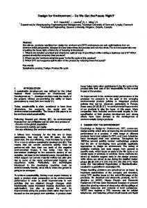
form a foundation to understand the utility of software frameworks designed to provide for an open system environment as such. The primary three characteristics of open engineering systems are: client (Requests actions for user, Optimus, etc...)
commAgent (Manages communications and operations that involve multiple services)
Robustness • (Type 1) Capacity to function despite noise • (Type 2) Capacity to adapt to a changing environment Modularity • Minimal interaction between functional segments (functional independence through minimal information content in interfaces) Mutability
Services (CAD, FEA, Display, RTTB, etc...)
Figure 1 -- Experiment One Communications Model
existing distributed services. This is similar to other frameworks, such as in (Han, et al., 1999): the brokering service returns a registered service that matches a task description requested by a client. In order to create a network of reusable agents that could provide the product realization process in the usage scenario through using a small core group of services, a communications agent was implemented, as shown in Figure 1. The communications agent (commAgent), looks up other services on behalf of a client program and manages the results of different remote requests in order to execute a series of operations in a process. The commAgent also managed the interaction between different services: given a request for an action such as "run experiment" or "run final model", the commAgent requests sub-tasks to be executed by the various services with information from the client. Thus the commAgent coordinates the various services and more importantly provides for an asynchronous message passing over the Internet such that multiple services can operate concurrently. The distributed services can be re-used in different processes by reconfiguring the commAgent to new tasks. 2.2 Evaluating Distributed Software Frameworks as Open Systems The P2 framework was an experimental prototype to test new technologies to provide a versatile framework for the operation of distributed resources in a heterogeneous environment with a minimum of structure and required software. It was designed to facilitate the rapid integration of new and existing software tools into re-configurable systems, giving distributed teams of engineers the ability to quickly instantiate and operate heterogeneous software tools in concert to solve design and manufacturing problems. Open engineering systems are systems of industrial products, services, and/or processes that are readily adaptable to changes in their environment which enable producers to remain competitive in a global marketplace through continuous improvement and indefinite growth of an existing technological base (Simpson, et al., 1998). The characteristics of open engineering systems
We present an analysis of the P2 framework, and subsequently the new prototype framework, based on these characteristics. 2.3 Experiment One - Results The P2 framework, based upon the PRE framework constructs, functioned well as a framework to allow an engineer to set up a small network of semi-automated software tools to solve engineering problems, as presented in (Gerhard, et al., 1999). Yet the P2 framework does not scale well to provide for open distributed systems consisting of changing technologies. Because of the nature of the PRE data and application constructs re-used in the P2 design, interfaces were not modular and changes to the system involved changing code at many points of distributed operation because of the high information content in the interfaces between applications. The framework is written such that the engineering data objects must be fit to the framework and not so that the framework is fit to the data. The framework design focuses on remote Apps, forcing services to be written to match each other's method calls and return objects (closely coupled) instead of common data objects (decoupled along application interface). For example, operational information about the remote services is available through the commAgent, including IP addresses, available operations (convert, execute, put_data...) at remote services, and the data that is expected to be returned in P2Data objects from calls to remote services. The P2Data property names used by the client and the services, as well as other control handshakes, must be coded into the commAgent and this is what creates dependencies between all distributed nodes of operation. The positive and negative features of the P2 implementation are summarized below in Table 1. The P2 framework is not a suitable framework for the experimental goals of the RTTB system (Rosen, 2000) (Herrmann and Allen, 1999). To experiment with different process configurations by restructuring the information flow in the RTTB dynamically, many parameters would need to be modified throughout the nodes of distributed RTTB software built within the P2 framework.
3
Copyright © 2000 by ASME
Table 1 -- Evaluation of P2 Implementation Positive Feature Services integrated through agent communication model
Java language
Negative Features PRE generalized design
Generic P2Data object instead of strongly typed data objects
Generic P2App objects instead of strongly typed application objects
Services integrated through agent communication model
Java Servlets
HTTP protocols
Resultant Effect Robust (1) • The commAgent can work around network failures and select best available resources • The commAgent provides asynchronous message handling in the Internet environment Robust (2) • Changing the locations of services only affects comm Agent Modular: Some functional independence is provided • Remote Services are reusable because process information is not hard-coded between services but within the commAgent. Mutable • Portable Java code can be compiled once and used on NT, IRIX, Solaris Resultant Effect Not modular or robust(2): functional independence is maintained • High information content in interfaces: distributed P2App objects have many interdepedencies because remote methods and data objects must be written to match each other • Difficult for distributed teams to program new integrated services without knowing about the implementation of many other distributed nodes. Not modular: functional independence is not maintained • Without strong object typing, the code within P2App objects must be examined to understand data placed in P2Data objects • Related code to access P2Data property values by label must be distributed through the client, commAgent, and services Not modular: Functional independence is not maintained • The P2App behavior is not made explicit through its interfaces - code with P2App must be examined to understand input/output • P2App implemented methods and their parameters must be known by a lookup service such as the commAgent Not robust (1) • Communications load and failure at commAgent critical - all communications must pass through the commAgent lookup service Not modular or robust (2): functional independence is not maintained • Coupled with the flaws of P2App and P2Data object design, the commAgent does not provide truly modular services - it is an integral part of managing the high information content of service interfaces Not robust(1) • Very difficult environment in which to debug distributed applications Not mutable • Cannot transmit binary data, only text encoded data - so many modifications that core JDK cannot be distributed as framework core
Since applications are not de-coupled from each other in several key ways, altering system behavior would involve system-wide changes to code. Improving on the flaws of P2 directly led us to the design for the second framework experiment. The issues raised by the P2 experiment will be addressed as the next framework experiment is described.
3. PRE-RMI FRAMEWORK The principal motivation for the second software framework experiment was to improve upon the Sandia P2 framework as an open system to provide for the rapid integration of distributed and dynamic software systems, such as the Rapid Tooling TestBed (RTTB). The lessons learned from the P2 system, summarized in Table 1, led to the second framework, PRE-RMI. The goal of the PRE-RMI system design was again to provide a framework for the operation of distributed resources in a heterogeneous environment with minimum of structure and required software. To achieve this, the lessons learned from P2 were directly applied from the first, namely, that modularity must be provided through 1) explicit application interfaces based on the data objects in the system and 2) minimal functional dependence between distributed nodes. It was desired to allow distributed programmers to integrate new services into the system without modifying or knowing the inner workings of other distributed nodes of operation: information content in application interfaces must be minimized. 3.1 Experiment Two - Event-Based Communications Model For the second experimental framework, PRE-RMI, the communications model was explicitly designed before the framework was implemented. Previously, the P2 framework focused on the distributed applications as the primary entity, forcing distributed programmers to fit data to generic constructs and inadvertently create interdependent application interfaces. A new communications model was needed to move beyond the problems inherent in the generic PRE framework constructs used in P2. To provide modularity and robustness in a changing environment, a new communications model was established with the engineering data as the primary entity, providing a common ground to write de-coupled interfaces between applications by applying a strongly typed object design to the information flow. PRE-RMI is an event-based communications model: the focus of the model is the information carried in the events that make up a process in a distributed environment. In this new communications model, agents send and receive events that are broadcast through event-channels. PRE-RMI was designed in an object-oriented style with interface and abstract classes that specify the framework behavior: these classes are extended to create functional objects in a distributed environment. The PRE-RMI event-based communications model is similar to the Java 1.1 AWT event model, which is
4
Copyright © 2000 by ASME
used to implement keyboard and mouse-driven interaction with window components in Java.
3.1.1 Events In PRE-RMI the principal unit of the framework design is on the information moved through the system, in terms of events. An event encapsulates the data in a key stage of a timebased process. An event in the PRE-RMI framework is similar to a message, but is used repeatedly with different values of its parameters. Events are passed between different nodes of distributed activity and encapsulate information with explicit accessor methods, a key element in achieving modularity; distributed services can be written to match the same accessor methods once system events are defined. All events in PRE-RMI are strongly typed: they inherit their core framework characteristics from a parent event object, but implement different private data variables and a taskspecific interface through public accessor methods. For example consider an event of type PrintEvent and an event of type DataBaseEvent, both of which inherit their structure from the parent class Event, and both of which implement unique methods, getPrintData or getSQLQuery, to access their different data variables, PrintData and SQLQuery. Once events are defined in a system, the services in the system are written to interact with these events by first recognizing their type, and then by using the defined getPrintData or getSQLQuery accessor methods that provide an interface to the event data. Once the events in a system are fully specified from an understanding of the information flow in process, these events can be distributed to all nodes of activity and distributed developers can work on different services independently of each other. Remote services are constructed to interact with the event interfaces, not each other, and are thus functionally decoupled through the event object interface. An example of an event in the Rapid Tooling TestBed is RP process/material selection. This event requires certain information from design events, including the part model, tolerances, and material specifications, and in turn leads to other events, such as process planning, by generating rapid prototyping machine and material specifications. An RPEvent can be written to encapsulate all of this data, at which point design services, machine/material selection services, and process planning services can be written to use the RPEvent. 3.1.2 Event Channels The event-based perspective intuitively implies the idea of an event-channel, which broadcasts events to remote services. The event-channel in PRE-RMI is similar to the idea of a "listener" in the Java AWT 1.1. To discuss the event-channel, the agent construct must also be introduced, although agents will be fully discussed shortly. Agents in PRE-RMI, such as a PrinterAgent and a DataBaseAgent for example, are distributed services that act upon events that arrive through event-channels, based on the event type, such as the previously discussed PrintEvent or DataBaseEvent. The system designer uses events
and event-channels to specify the flow of information to agents that execute processes in concert with each other: services can be aggregated such that they support problem decomposition (Han, et al., 1999). Parallel courses of action can be instantiated easily while information flow and communications load is clearly segregated into groups of agents linked by eventchannels. Instead of a centralized brokering service as embodied in the commAgent model of the first experiment, the eventchannel is a decentralized and transparent routing service between agents that are to share information through events. Agents register themselves with event-channels through a remote subscription call in order to receive the events that are broadcast through the event-channel by other agents. The event-channels provide agents the ability to register and remove themselves, thus providing a robust (type 2) and modular interface between agents. A distributed system can be reconfigured by changing the connectivity between different agents with multiple event-channels. Event channels provide the lookup service and errorhandling functionality of the communications agent model, but without task-specific agent functionality. The event-channel has been implemented to provide robustness both to errors and noise in the environment and to a changing environment. An event-channel (1) maintains a current list of available agents by regularly checking for connectivity, removing agents that do not respond from the broadcast list, and (2) tracks the events that flow through the event-channel, registering errors unless at least one agent acts upon any given event. Thus an agent will receive a message if an event that it sent to an event-channel goes unhandled, presumably because other distributed agents that were expected to act on the event in the event-channel became disconnected or failed to execute correctly. An agent on an event-channel, logging the events that flow through the channel could capture a history of communications through an eventchannel. Text logs are also output from the event-channel for system monitoring.
3.1.3 Agents An agent in PRE-RMI provides services defined by the event types it is able to accept and generate, such as our example PrintEvent or DataBaseEvent. Agents are not called upon by making a call to one of their services, as in the P2 framework, but by giving them an event through the eventchannel interface. An agent can send and receive events to and from multiple channels: each agent has a set of receiving channels and sending channels that are maintained separately. Agents can be placed on different event-channels without changing any code in the channel or the agent. When an agent is instantiated, the IP addresses of the sending and receiving event-channels are specified over the command line and the agent registers itself. Specific agents can only interact with certain events that are clearly specified in a list of acceptable events when the agent is instantiated. When an event is received from an event-
5
Copyright © 2000 by ASME
channel by an agent, the agent checks the event object type: if the event object type is not on the agent’s events-to-accept list, no action is taken. If the event can be accepted, it is handled by its object type, such as “PrintEvent”, an event identification such as “Postscript” or “PDF”, and a handling identification, defining the event as “handled” or “unhandled”. For example, a PrintAgent may only accept events of type "PrintEvent" and manage a specialized plotting machine, and a DataBaseAgent may only accept events of type "DataBaseEvent" and manage a database of product information. Agents can interact with events by the event identification and handling tags and act appropriately. For example a PrintAgent may ignore an unhandled PrintEvent until a DataBaseAgent has added key information to a document and in turn marked it as handled. Because an agent can send and receive a well-defined set of events, event accessor methods, event constructors, and agent constructors specify agent interfaces, including the types of the data objects used in the interface: distributed programmers can then write agents that are de-coupled from each other along the event accessor methods. For example, the PrintAgent will access documents to be printed in a PrintEvent through the method "getPrintData". A DataBaseAgent may store the document automatically by also receiving the PrintEvent and accessing the document through "getPrintData". An agent may provide an interface with software tools through wrappers, or coupled with different event-channels, it may also coordinate the behavior of several other agents, as did the communications agent in the P2 experiment. Thus if several agents exist that perform the same task, they can be grouped on an event-channel and a managing agent can choose among them, utilizing the best resource for the job or working around situations when some resources are unavailable.
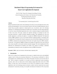
3.1.4 System Overview With a system of channels and agents, complex behaviors can be implemented in a modular and robust fashion. Highlevel system behavior consists of the interactions between agents, and is determined by how the agents are linked with event-channels and by what events are sent through the channels. A diagram of agents and event-channels is shown in detail in Figure 2, representing one configuration of six agents. An example usage of this network of agents and event-channels is then presented in Table 2. Note that because event-channels throw error events when events are not handled in the channel, any agent that sends events to an event-channel must also receive events from that event-channel in order to act on error events. In this example, Agent 1 interprets client requests, analyzes them, and generates an event X in event-channel A at the beginning of a process. Agent 2, servicing both channels A and B as a database service, accepts the unhandled event X, supplies needed information, and resends X as handled. Agent 3, which previously ignored the unhandled event X on A, accepts X as handled, performs an analysis using the database information, and sends a new event, Y to event-channel B. Agents 4 and 5
Receive A
Channel A
Receive A
Agent 1
Agent 2 Send A
Send A
Receive A
Receive A
Agent 6
Send B
Receive B
Agent 3
Receive B
Receive B
Receive B
Send B
Channel B
Receive B
Agent 5
Agent 4 Send B
Send B
Figure 2 -- Connection of Agents with Channels
Table 2 -- Agent Interaction Shown in Figure 2 Agent
Channel A Send + Receive Send + Receive
Channel B -
3
Receive
Send + Receive
4
-
Send + Receive
5
-
Send + Receive
6
Receive
Receive
1 2
Send + Receive
Events
Function
Generate: X Accept: X,Y
Client
Accept: X, Y Generate: Y Accept: X, Y Generate: Y Accept: Y Generate: Y Accept: X, Y, Z
Database for Agents 1,3,4 and 5 Manage Agents 4 and 5 and display results Analysis of Y
Analysis of Y
Log all activity in A and B
wait until Agent 2 handles event Y, providing different information from the database as dependent on the results of Agent 3 in Y. Upon receiving event Y as handled, both Agent s 4 and 5 perform an analysis that yields event Z on Channel B. Agent 2 ignores events of type Z and does nothing. Agent 3 accepts event Z as unhandled, examines the results, and displays the appropriate information to a user - which concludes the process initiated by event X. Agent 6 only receives events: it logs all X, Y, and Z events that flow through both A and B in a central monitoring service.
6
Copyright © 2000 by ASME
3.2 PRE-RMI System Design In order to implement a lightweight and portable framework, PRE-RMI was implemented using Java-RMI (Remote Method Invocation), which is distributed in the Sun Microsystems Java Development Kit, http://java.sun.com/jdk/. Java-RMI enables distributed Java objects to call each other's methods over the Internet using a simple API and the RMIRegistry tool, provided in the JDK. Thus all that is needed to install a PRE-RMI framework on any platform is the standard JDK, which is free, and the PRE-RMI classes. An understanding of the RMI communication mechanism can be gained from the tutorial at: http://java.sun.com/docs/books/tutorial/rm i/index.html.
3.2.1 Core Framework Classes A small set of objects was designed to implement the PRERMI communications model in Java, consisting of a set of interfaces, Compute, Channel, and EventInterface, and a set of abstract classes, ComputeAgent, EventChannel, and Event. The interfaces specify the public methods and their signatures for the objects in the PRE-RMI system, which describes how different remote objects interact with each other based upon the communications model. The first interface, Compute, defines the public methods of the ComputeAgent abstract class. This includes handleEvent, which takes an Event as an argument, and getComputeName, which returns the RMI name of the Compute. public interface Compute extends Remote { public boolean handleEvent(Event e) throws RemoteException; public String getComputeName() throws RemoteException; }
The second interface, Channel, defines the public methods of the EventChannel abstract class. This includes getChannelName, which returns the RMI name of the Channel, remove- and addEventReceiver, which takes a Compute as an argument, and pushEvent, which takes an Event as an argument. public interface Channel extends Remote { public String getChannelName() throws RemoteException; public void removeEventReceiver(Compute C) throws RemoteException; public void addEventReceiver(Compute C) throws RemoteException; public void pushEvent(Event e) throws RemoteException; }
The final interface, EventInterface, defines the public methods in the Event abstract class. The public methods include getEventID, getEventSource, setEventSource, setEventHandler, queryEventHandled, and setEventHandled.
public interface EventInterface extends Serializable { public String getEventID(); public String getEventSource(); public void setEventSource(String SourceName); public void setEventHandler(String HandlerName); public boolean queryEventHandled(); public void setEventHandled(boolean Handled); }
The abstract classes, which implement the given interfaces and cannot themselves be instantiated, comprise the framework used to implement a distributed system with PRE-RMI along with a simple web server, consisting of two classes, to make the class files available to the Java-RMI communications mechanism. To describe these objects, the method signatures are provided without any other implementation details. The Event abstract class is very simple: it only provides the accessor methods for the basic operations that occur with an event. The constructor is not shown: this is where the EventID, EventSource, and EventName variables are set. By default, the event is designated as unhandled. A Compute that acts on this Event can use the setEventHandled and setEventHandler to denote that it has successfully acted on the Event. Other Computes can then interrogate the status of the Event with the queryEventHandled method. public abstract class Event implements EventInterface { public String getEventName() public String getEventID() public void setEventSource(String SourceName) public String getEventSource() public void setEventHandler(String HandlerName) public String getEventHandler() public void setEventHandled(boolean Handled) public boolean queryEventHandled() }
The EventChannel abstract class provides an implementation for all the public methods in the Channel interface as well as the private pollReceivers method, the trackEvent method, the ReceiverTracker thread, and the EventPusher thread. When a remote Compute wishes to send an Event, it calls the public pushEvent method, which in turn calls pollReceivers to ensure that the list of registered receiving Computes is current, and then creates an EventPusher thread for each receiving Compute. Each EventPusher thread call passes the Event to the handleEvent method of a remote receiving Compute and then calls trackEvent, waiting until the receiving Compute returns true or false to indicate success. If none of the remote Computes monitoring the channel return true, an ErrorEvent is thrown by the trackEvent method. A remote Compute can call the public add- and removeEventReceiver methods of the EventChannel to add and remove itself from the broadcast list. The public getChannelName method returns the EventChannel RMI name. No methods are left abstract: only a
7
Copyright © 2000 by ASME
protected void setEventChannels(String [] args) protected abstract boolean execute(Event e) throws RemoteException; }
main method must be implemented in classes that inherit from EventChannel. public abstract class EventChannel extends UnicastRemoteObject implements Channel{ private class ReceiverTracker implements Runnable private class EventPusher implements Runnable
Interfaces
Event Interface
Compute
Channel
public String getChannelName() throws RemoteException public void pushEvent(Event e) throws RemoteException public synchronized void addEventReceiver(Compute C) throws RemoteException public synchronized void removeEventReceiver(Compute C) throws RemoteException private void pollReceivers() private synchronized void trackEvent(Boolean eventHandled, String handlerRMIName, Event e, Vector EventHandlers)
Abstract Classes
Event
Compute Agent
Event Channel
Implemented Classes
RP Event Database Event Gear Design Event
RP Agent Database Agent Gear Design Agent
RP Event Channel Database Event Gear Design Channel
Implementation Order for Functional Objects
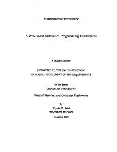
Figure 3 -- PRE-RMI Interfaces, Abstract Classes, and Example Implementation Classes
}
The ComputeAgent abstract class provides an implementation for all the public methods in the Compute interface as well as the protected methods destroy, canAccept, sendEvent, and setEventChannels. The protected method execute remains abstract, to be implemented in agents that inherit from the ComputeAgent: this is where task-specific code is inserted to manage the details of different events. The public method getComputeName returns the ComputeAgent RMI name. In the public handleEvent method, called by remote EventChannels to send an event to the ComputeAgent, the canAccept method is called, and if this returns true, the execute method is called. The setEventChannels method is called to add sending and receiving EventChannels, typically in the main method of an agent inheriting from ComputeAgent. Sending EventChannels are stored in a broadcast list; to monitor a given EventChannel, the remote EventChannel addEventReceiver method is called. The sendEvent method broadcasts an Event by creating a ChannelPusher thread, which calls the pushEvent method of each remote EventChannel on the broadcast list. The destroy method calls the remote removeEventReceiver method for each EventChannel on the receiving list. SendEvent and destroy are intended to be used in an agent that inherits from ComputeAgent, typically in an implementation of the execute method. public abstract class ComputeAgent extends UnicastRemoteObject implements Compute{ private class ChannelPusher implements Runnable public String getComputeName() throws RemoteException public boolean handleEvent(Event e) throws RemoteException protected void destroy() protected boolean canAccept(Event e) protected synchronized void sendEvent(Event e) throws RemoteException
3.2.2 Implementation Classes In order to implement task-specific behaviors in the PRERMI system, functional events, event-channels, and agents must be created by extending the core Event, ComputeAgent, and EventChannel abstract classes, respectively. Figure 3 illustrates the progression of interfaces and abstract classes to implementation classes. All framework communications behavior is already implemented at the level of the abstract classes, but task-specific behaviors are added through the extension of these classes. Specifically, the Event class must first be extended into one or more events with private data variables and public data accessor methods to encapsulate the data in the process to be implemented. This is done first so as to define the information that agents will use when they are implemented. In an example GearDesignEvent, designed to carry information about parts in a gear transmission for a power drill, accessor methods have been provided for the necessary engineering data. Some of the data, such as the pitch, numbers of gear teeth, and so on are provided in the GearDesignEvent constructor and then accessed through the appropriate getXXX methods. Access to other data objects, such as analysis results and part models, are provided through setXXX and matching getXXX methods when the event is handled. public class GearDesignEvent extends Event implements EventInterface{ public String getTrailFile_name() public String getN_teethSun() public String getN_planets() ... public String getPitch() public String getTooth_angle() public String getApplied_load() public void setStressResults(String Stress) public String getStressResults()
8
Copyright © 2000 by ASME
public void setSunSTLModel(byte[] sunModel) public void setSunVRMLModel(byte[] sunModel) ... public byte[] getSunSTLModel() public byte[] getSunVRMLModel()
Receive A Client Agent
EventChannel A (DesignEventChannel)
Send A
Receive A
Receive A
Display Agent
RP Agent
Receive B
Receive B Receive B Process Plan Agent
protected boolean execute (Event e) throws RemoteException { if(e instanceof compute.ErrorEvent) //handle error event if //event sent from here { ... } if(e instanceof event.GearDesignEvent) { if(e.queryEventHandled()) { //if event handled, no need to do anything return false; } GearDesignEvent gde = (event.GearDesignEvent) e;
Send B
EventChannel B (RTTBEventChannel
Send B
RP Machine OP Agent
Send B
Table 3 -- Agent Interaction Shown in Figure 4. Agent Client Agent
Channel A Send + Receive
Channe lB -
Gear Agent
Send + Receive
-
RP Agent
Receive
Send + Receive
Process Planning Agent
-
Send + Receive
RP Machine OP Agent Display Agent
-
Send + Receive
Receive
Receive
} }
4. A USAGE SCENARIO IMPLEMENTATION In Figure 4 and Table 3 we illustrate the example gear transmission usage scenario, originally presented in (Gerhard, et al., 1999), as implemented in the PRE-RMI framework with integrated design, analysis, and RTTB software. A set of GearDesignEvents and RPEvents propagate through the system and eventually result in a BuildEvent. At the designer's workstation the DSIDES and MiniTab software is used to solve the transmission design problem and build response surfaces for particular instances. Through a ClientAgent, the designer can
Receive B
Figure 4 -- Distributed Usage Scenario
if (gde.getEventID().equals("Experiment")) { //call CAD/FEA wrappers with gear //design event params return true; } return false;
A main method must also be provided to instantiate the agent from a command line or batch interface, defining a list of acceptable events and binding the ComputeAgent with the RMIRegistry for remote functionality. Finally, to define usable event-channels to segregate the flow of different events to different agent, all that must be done is to extend the EventChannel class with a main method to bind the EventChanel to the RPMIRegistry for remote functionality.
Gear Agent
Send A
}
The ComputeAgent class must then be extended into one or more agents that interact with Events. This is done by implementing the "execute" method, previously left abstract in ComputeAgent, to use the Events and Event accessor methods that have been defined. Some example code is shown below illustrating the control structure and the use of Event accessor methods in a GearAgent that accepts the GearDesignEvent and manages wrapped CAD and FEA software.
Receive A
9
Events
Function
Generate: Gear Design Event Accept: Gear Design Event Accept: Gear Design Event Accept: RP Event Generate: Build Event Accept: Y Build Y
Designer Submits FEA and RP Requests
Accept: Gear Design Event, RP Event, Build Event
Manages ProEngineer and AnSys Manage Machine/Material Selection Tool Manages SLA Process Planning Tool
Relays model files to RP Machine Operator Displays Results of Gear/RP/Process/ Planning/RPOP Agents to Designer
Copyright © 2000 by ASME
generate a GearDesignEvent in the DesignEventChannel, which is handled by the GearAgent, managing the automated execution of ProEngineer and AnSys with software wrappers. For experimental runs to build a response surface of stress performance, the GearAgent returns FEA results to the designer through the ClientAgent: all other agents ignore the event because it is tagged as an "experiment" with the EventID parameter. For a final run to prototype a part, the GearAgent returns part models of all the gears in the transmission in several file formats, as well as the FEA analysis: the handled GearDesignEvent, tagged with EventID "final", is accepted by both the DisplayAgent, which displays the final analysis results and a VRML representation of the part model, and the RPAgent, which manages the selection of the RP machine and material combinations. The RPAgent and DisplayAgent are on both event-channels. With the results of the GearDesignEvent, the RPAgent generates a RPEvent in the RTTBEventChannel, which is handled by the ProcessPlanningAgent. Once the RPEvent is handled and slicing configurations have been evaluated, the Display agent shows the RP machine, material, and process planning information, such as the resulting part build times and tolerances. Given a confirmation by the designer at the DisplayAgent, the human RP machine operator is provided part models and process information through a BuildEvent. 5. CRITICAL REVIEW The PRE-RMI communications model and system design provide many improvements over P2. In general the framework is made from the flow of engineering data instead of fitting the flow of data to the framework: events can be understood apart from the agents that act on them. The Java RMI design is truly mutable as it only depends upon the standard JDK for its entire operating environment: no web server is needed and pure Java is used to transmit binary files, as opposed to the P2 design. The Java RMI implementation provides significantly more detailed error messages from the underlying RMI objects, simplifying user interaction and debugging vastly over the Java Servlet design. Given the event-based communications model, modularity and robustness (type 2) are improved. Agents have an explicit interface through event-channels. Agents accessing the same information are completely de-coupled from each other through the explicit definition of events accessor methods. The operations that agents perform are made explicit through the events that they accept and generate. The system process information is not stored in a central communications agent but rather distributed to the nodes of activity where developers can access them for implementation and modification, providing robustness (type 2) to change at distributed nodes. Remote agents can be maintained, modified, and added independently of the rest of the system. Once the information flow in a process is defined in events, agent developers do not need to know the internal details of remote agents, only the relevant event types.
There is no central communications agent that manages the implemented methods and parameters of the agents; thus the agents are de-coupled from a central lookup service. Eventchannels aggregate services such that they support problem decomposition. Agents can coordinate other agents as grouped by event channels to handle asynchronous message passing in Internet environment, providing robustness (type 1 and 2) to communications failures. Further addressing robustness (type 1), lookup services are performed by eventchannels that distribute communications load, monitor agent connectivity, and monitor unhandled events; agent and eventchannel interaction is completely multithreaded to prevent dead locks. Modular event-channel interfaces allow agents to register and remove themselves with channels such that no addresses are hard-coded into the system: different process configurations are achievable by simply changing the connections. 6. CLOSURE The PRE-RMI system has provided a robust and modular framework for distributed computing over the Internet and will be the framework used to implement the Rapid Tooling TestBed. Although we have made progress, we have identified significant issues for further development, namely: • Using Java Remote Activation to provide persistent data objects in the PRE-RMI environment. Thus, agents and event-channels would not need to be manually started by a system operator, they could instead be remotely activated. • The expansion of capabilities in the RTTB now that a stable framework has been developed. Database services in the RTTB will be implemented to provide a knowledge base of design and manufacturing related information for families of components as well as to capture process related information. • Studying the effects of distributing resources. Timecritical or computationally intensive processes that occur using distributed resources may be adversely affected by the distribution itself. We will use the modular nature of the PRE-RMI framework to explore the effects of changing the configuration of the RTTB upon the quality of the products. • Providing true delegation of design and manufacturing tasks to agents, as well as maintenance of system integrity. We desire to explore knowledge capture and social behavior as in (Jin and Zhou, 1999), for example it is desirable to design an agent that can configure a process for a task given user priorities. We have created a valuable prototype system because of our emphasis on this future growth through an open systems perspective. Finally, we have demonstrated the successful integration of CAD simulation tools, design software tools, design visualization and communications tools, and rapid prototyping tools. The integration of these tools into a product
10
Copyright © 2000 by ASME
realization environment such as PRE-RMI allows the engineering designer to do more with less, more than ever before. ACKNOWLEDGEMENTS Support from NSF Grant DMI-9618039 and DMI-9612327 is gratefully acknowledged. Jonathan Gerhard was a Woodruff Fellow for a portion of the time this work was being performed. The cost of computer time was underwritten by the Systems Realization Laboratory. Thanks are extended to Dr. Ernest Friedman-Hill for inspiration, guidance, and patience. REFERENCES Chen, W., Allen, J. K., Mavris, D. and Mistree, F., 1996, "A Concept Exploration Method for Determining Robust TopLevel Specifications," Engineering Optimization, Vol. 26, No. 2, pp. 137-158. Gerhard, J.F., Duncan, S.J., Chen, Y., Allen, J.K., Rosen, D., Mistree, F., and Dugenske, A., (1999) “Towards a DecisionBased Distributed Product Realization Environment for Engineering Systems,” ASME Computers and Information in Engineering Conference, Las Vegas, NV, DETC99/CIE-9085. Han, C.S., Kunz, J.C., and Law, K.H., (1999) "An InternetBased Distributed Service Architecture," ASME Computers and Information in Engineering Conference, Las Vegas, NV, DETC99/CIE-9077.
Herrmann, A.E. and Allen, J.K., (1999) “Selection of Rapid Tooling Materials and Process in a Distributed Design Environment,” ASME Design For Manufacture Conference, Las Vegas NV, DETC99/DFM-8930. Jin, Y., Zhou, W., "Agent-Based Knowledge Management for Collaborative Engineering," ASME Computers and Information in Engineering Conference, Las Vegas, NV, DETC99/CIE-9022. Kim, H., Lee, J.Y., Han, S., "Process-Centric Distributed Collaborative Design Based on the Web," ASME Computers and Information in Engineering Conference, Las Vegas, NV, DETC99/CIE-9081. Pancerella, C. M., and Whiteside, R. A., 1998, "The Integration of Manufacturing Enterprises Using Corba," International Journal of Agile Manufacturing, Vol. 1(2) pp. 155-172. Rosen, D.W., "Design-to-Manufacture Information Transfer in the Context of Solid Freeform Fabrication Technologies." Book chapter in: Knowledge Intensive Computer Aided Design, Ed. S. Finger, T Tomiyama, and M. Mantyla, Kluwer Academic Publishers, Boston, 2000. Simpson, T.W., Lautenschlager, U., and Mistree, F., (1998) “Mass Customization in the Age of Information: The Case for Open Engineering Systems,” in Porter, A.L. and Reed, W.H., Eds. The Information Revolution: Current and Future Consequences, Ablex Publishing Corporation, Greenwich, CT.
11
Copyright © 2000 by ASME