L3-Communications, Billerica, MA, 01821. David J. Wingâ . NASA Langley Research Center, Hampton, VA, 23681. Robert Vivonaâ¡ and Jose-Luis Garcia-Chico§.
A Distributed Trajectory-Oriented Approach to Managing Traffic Complexity Husni Idris, Ph.D.* L3-Communications, Billerica, MA, 01821 David J. Wing† NASA Langley Research Center, Hampton, VA, 23681 Robert Vivona‡ and Jose-Luis Garcia-Chico§ L3-Communications, Billerica, MA, 01821
In order to handle the expected increase in air traffic volume, the next generation air transportation system is moving towards a distributed control architecture, in which ground-based service providers such as controllers and traffic managers and air-based users such as pilots share responsibility for aircraft trajectory generation and management. While its architecture becomes more distributed, the goal of the Air Traffic Management (ATM) system remains to achieve objectives such as maintaining safety and efficiency. It is, therefore, critical to design appropriate control elements to ensure that aircraft and groundbased actions result in achieving these objectives without unduly restricting user-preferred trajectories. This paper presents a trajectory-oriented approach containing two such elements. One is a trajectory flexibility preservation function, by which aircraft plan their trajectories to preserve flexibility to accommodate unforeseen events. And the other is a trajectory constraint minimization function by which ground-based agents, in collaboration with air-based agents, impose just-enough restrictions on trajectories to achieve ATM objectives, such as separation assurance and flow management. The underlying hypothesis is that preserving trajectory flexibility of each individual aircraft naturally achieves the aggregate objective of avoiding excessive traffic complexity, and that trajectory flexibility is increased by minimizing constraints without jeopardizing the intended ATM objectives. The paper presents conceptually how the two functions operate in a distributed control architecture that includes self separation. The paper illustrates the concept through hypothetical scenarios involving conflict resolution and flow management. It presents a functional analysis of the interaction and information flow between the functions. It also presents an analytical framework for defining metrics and developing methods to preserve trajectory flexibility and minimize its constraints. In this framework flexibility is defined in terms of robustness and adaptability to disturbances and the impact of constraints is illustrated through analysis of a trajectory solution space with limited degrees of freedom and in simple constraint situations involving meeting multiple times of arrival and resolving a conflict.
*
Lead Research Analyst, 300 Concord Road, Suite 400, AIAA Member Principal ATM Research Engineer, Mail Stop 152 ‡ Principal Research Engineer, 300 Concord Road, Suite 400, AIAA Associate Fellow § Research Analyst, 300 Concord Road, Suite 400, AIAA Member †
1
I.
Introduction
T
he Next Generation Air Transportation System (NextGen) is expected to receive up to three times the current traffic demand by the year 2025.1 In order to handle the expected increase in air traffic NextGen will introduce major transformations in Air Traffic Management (ATM); three examples of which are net-enabled information access, performance-based services, and aircraft trajectory-based operations.1 Net-enabled information access will substantially increase information availability promoting greater shared awareness of system operations among users and service providers. Net-enabled information access is exemplified by emerging technologies such as the Automatic Dependent Surveillance Broadcast (ADS-B) which enables sharing of aircraft-based position and intent information among airborne and ground-based agents. Performance-based services will make access to National Airspace System (NAS) resources, such as runways and airspace volumes, dependent on the equipage and capability of the aircraft. This promotes users to equip their aircraft and service providers to provide access to scarce NAS resources according to performance levels of aircraft. Trajectory-based operations will manage NAS resources by requiring aircraft to precisely follow custom-made 4-D trajectories consisting of a specified path and along-path time conformance requirements. This promotes prescribing and accurately following trajectories that ensure separation and optimize traffic flow management over different time horizons. These capabilities enable a more optimal allocation of functions among the agents of the air traffic system.2 One such allocation scheme proposes moving the ATM system towards a distributed control architecture.3,4 This distributed architecture delegates to the pilot more authority in determining and modifying the aircraft trajectory; currently this authority resides mainly with the ground-based controller. The premise is that distributed control mitigates the controller workload as a constraint against increasing airspace capacity, because introducing more traffic introduces additional responsible decision makers (pilots) enabled by advanced sensor, communication, and decision support technologies. While the architecture of the ATM system becomes less centralized and more distributed, its goal remains to achieve objectives such as maintaining safety and efficiency at acceptable levels. A key research question asks whether a distributed control architecture will be capable of satisfying these ATM objectives. A positive answer has important implications on the new role of centralized control, taking on higher level supervisory control functions such as monitoring and intervention, as opposed to lower level active control, thus enabling capacity gains and cost savings. Therefore, in the distributed control architecture each individual aircraft is responsible for generating and maintaining a trajectory that achieves the ATM objectives for that flight in addition to any self-interest objectives. To this end it is critical to design the distributed architecture with appropriate elements that ensure individual aircraft actions achieve the overall ATM objectives. Prior research on distributed ATM concentrated on the investigation of sharing the primary function of separation assurance between pilots and controllers. A number of research efforts investigated and reported algorithms suitable for conflict resolution in a distributed control environment: Hill, et al. suggest a satisficing game theoretic approach for distributed air traffic control.5 Wollkind, et al. reported a cooperative negotiation algorithm for conflict resolution, trading shared utility information using a monotonic concession protocol.6 Versteegt and Visser use traffic complexity as a criterion to resolve conflicts in a free flight sector while reducing the traffic load.7 To assist the pilot in separation assurance, automation such as the Autonomous Operations Planner (AOP) is designed to provide conflict detection and resolution advisories in the cockpit.8 Genetic algorithms to resolve conflicts between aircraft pairs are reported associated with the AOP research.9,10 Early experiments of mixed distributed and centralized separation assurance showed promising results in terms of the impact on workload and efficiency.11,12,13 This paper describes two newly proposed functions for the distributed ATM system: A trajectory flexibility preservation function and a trajectory constraint minimization function. The trajectory flexibility preservation function enables an aircraft to plan its trajectory such that it preserves a requisite level of maneuvering flexibility in accommodating unforeseen disturbances, stemming for example from other traffic and from weather activity. The trajectory constraint minimization function enables ground-based agents, in collaboration with air-based agents, to impose just-enough constraints on trajectories to achieve ATM objectives, such as separation assurance and flow management. The concept hypothesizes that by each individual aircraft preserving its own trajectory flexibility, aggregate system objectives, such as maintaining acceptable traffic complexity (complexity defined as proneness to compromising safety), are naturally achieved. It also hypothesizes that minimizing the constraints imposed on a trajectory, without jeopardizing the intended ATM objectives, increases its flexibility. In this paper, Section II describes conceptually how the two functions of trajectory flexibility preservation and constraint minimization operate in a distributed control architecture that includes self separation. The concept and its underlying hypotheses are illustrated through hypothetical scenarios involving conflict resolution and flow
2
management. Then a functional analysis is described in Section III where each of the three functions is decomposed into monitoring and action components, and the interaction and information flow between them is demonstrated schematically. Section IV gives further insight into the concept by describing it in an analytical framework for defining metrics and developing methods to preserve trajectory flexibility and minimize its constraints. In this framework flexibility is defined in terms of robustness and adaptability to disturbances. Furthermore, the impact of constraints is illustrated through analysis of a trajectory solution space with limited degrees of freedom, namely speed variation along the aircraft path, and in simple constraint situations involving meeting multiple times of arrival and resolving a conflict. Finally concluding remarks and future work are summarized in Section V.
II. Concept of Distributed Trajectory Flexibility Preservation and Constraint Minimization
Negotiate Constraints
Ó
Pilot
Ó
Ó Ó
Ó Ó
Ó Ó
Ó
Ó
Ó
Ó Ó
Preserve Flexibility
Ó
Ó
Ó Ensure Separation
Ó
Ó Ó
Pilot
Ó
Ó
Distributed/Automated Complexity
Ó
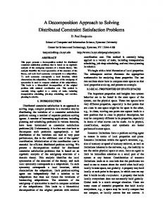
Figure 1 illustrates the allocation in the distributed ATM architecture of the three functions: separation assurance, trajectory flexibility preservation and trajectory constraint minimization. In this mixed operations, distributed environment separation assurance is shared between the pilot (for self-separating aircraft) and the air traffic controller (for ground-controlled aircraft) and acts in a short time horizon depicted by the shorter cones extending from each aircraft. The flexibility preservation function is a pilot function that complements the pilot’s separation assurance function but acting on a larger time horizon as depicted by the extended cone shapes. The constraint minimization function is allocated mainly to the ground based traffic manager to impose just-enough restrictions on the aircraft to meet ATM objectives. However, a collaborative role allows the pilot to negotiate constraints with the ground traffic manager. Each of the three key functions, the relationships between them, and their impact on NAS performance indicators such as capacity and complexity, are described next.
Ensure Separation Preserve Flexibility
Ó
Negotiate Constraints Centralized Complexity (e.g. Controller workload)
Ensure Separation
Mitigate Complexity
Controller
Traffic Manager
Minimize Constraints
Figure 1 Distributed ATM architecture with separation assurance, trajectory flexibility preservation, and trajectory constraint minimization A. Separation Assurance Separation assurance is the most central function of air traffic control, taking priority in the short time horizon and for safety reasons, over other functions such as expediting traffic and implementing traffic flow management initiatives. In centralized control separation assurance is the responsibility of the air traffic controller who monitors and vectors aircraft within an airspace volume to maintain the minimum separation requirements. On the other hand, in distributed control, each aircraft (i.e. pilot/automation system) is responsible to maintain separation from its surrounding traffic. As a result the centralized complexity (which represents controller workload and proneness to committing separation violation errors)14-18 is reduced because the controller is relieved from the active separation assurance task for self-separating aircraft. The premise is that the airspace can accommodate more traffic as a result because the number of pilots who are responsible for separation assurance scales with the increased traffic. Pilots are afforded cockpit automation such as AOP in order to assist with conflict detection and resolution and maintain their workload at an acceptable level. A notion of distributed/automated complexity is introduced that represents the level
3
of proneness to separation violation errors in the new distributed/automated environment.19 Therefore, traffic complexity may be represented and mitigated differently in a distributed/automated-control environment than in the usual centralized/human-control environment. Whether centralized or distributed, resolving predicted conflicts is more critical and is required to be more accurate for conflicts that are predicted closer to the current position of aircraft. The further out the predicted conflicts the less critical their resolution is because prediction is less accurate and the situation is subject to change as time progresses. Separation assurance is, therefore, the most critical function of cockpit automation such as AOP in the near time horizon, and takes priority over any other function in this horizon. In the current AOP concept, conflict resolution is performed only for conflicts predicted in the next ten minutes, from the current aircraft state, and these conflicts are resolved for the next twenty minutes. The separation assurance horizon is shown as the dark short cone expanding from each aircraft in Figure 1. B. Trajectory Flexibility Preservation Trajectory flexibility preservation is envisioned as an airborne function that complements airborne-based separation assurance. The main objective of this function is to plan the aircraft trajectory in a manner that affords the aircraft sufficient flexibility, particularly in preserving its ability to accommodate unforeseen disturbances. These disturbances may stem for example from other traffic and from weather activity. Flexibility preservation complements separation assurance both within the conflict resolution horizon and outside it within the flexibility planning horizon as shown by the extended cone shapes in Figure 1. In the conflict resolution horizon flexibility is used to select from many conflict resolution solutions one that affords the aircraft more flexibility, for example to adapt to unexpected behavior by the intruder traffic. One example of such behavior is the coincidence conflict situation shown in Figure 2. In this situation two conflicts are predicted between two unrelated pairs of aircraft as shown in the left side of the figure. If the two ownship aircraft maneuvered as shown in the left side of the figure to resolve their respective predicted conflicts, without coordination, a new coincidental conflict may arise between them. Although the flexibility preservation function does not explicitly coordinate between the two aircraft, it is intended to assist each ownship to reduce the risk of conflict due to the unpredictable behavior of the surrounding traffic. Hence with this function, each ownship aircraft may select a more flexible trajectory anticipating the unforeseen behavior of the other aircraft and minimizing the exposure to it. For example, in the right side of Figure 2 each of the ownship aircraft decided instead to maneuver away from the other ownship, reducing or eliminating the chance of a coincidence conflict situation.
Conflict Resolution without Flexibility Preservation Previous conflict
Conflict Resolution with Flexibility Preservation Previous conflict
Previous conflict
Previous conflict
New “coincidence” conflict
Non-coordinated coincidental resolutions ready for execution
Distributed resolutions minimizing risk exposure to traffic
Active routes
Ownship Unrelated conflict pairs
Look-Ahead Horizon
Figure 2 Flexibility preservation avoiding coincidence conflicts
4
Avoided “coincidence” conflict
Outside the conflict resolution horizon and within the flexibility preservation horizon the flexibility preservation function plans the aircraft trajectory to minimize its exposure to disturbances other than the possibility of loss of separation. This is because in such a long horizon conflict prediction is rather inaccurate and does not warrant conflict resolution. Therefore, the main disturbances in this horizon that the flexibility preservation function is concerned with include, for example, weather cells and dense traffic areas. While maintaining the required separation from the other traffic is not ensured in this horizon, the flexibility preservation function positions the aircraft optimally to reduce the probability of conflict in the future. More generally it is hypothesized that the flexibility preservation function results in naturally producing traffic situations that are less complex than without the application of the function. Figure 3 depicts an example involving aircraft maneuvering around convective weather cells. Because of the reduced airspace capacity aircraft compete for small gaps between the weather cells. On the left side of the figure each aircraft, while planning its trajectory, assesses its flexibility, using a flexibility metric that reflects its exposure to risk and ability to mitigate it. Given the weather and traffic situation each aircraft questions whether it should avoid the airspace entirely or could modify its trajectory to increase its flexibility. If the aircraft proceeded along their headings as depicted in the left side of the figure, a complex traffic situation arises causing excessive congestion and possibly a high conflict rate in the airspace between the weather cells. On the other, the right side of the figure displays a more structured and streamlined traffic pattern that would result if each aircraft made a decision to increase its flexibility – by limiting its exposure to congestion and proximity to the other traffic and the weather cells. As was shown notionally in Figure 1, because the flexibility preservation function results in reducing the traffic complexity in the new distributed environment, the ground controller workload is also reduced, while performing monitoring and supervision, as the traffic is more structured and the chance of conflict is reduced.
Without Flexibility Preservation
With Flexibility Preservation
Ownship Flexibility metric
Hypothesis: If all aircraft apply flexibility preservation function, complexity automatically will be reduced
Airborne flexibility function will question: Do I have enough flexibility to safely proceed? Can I modify my trajectory to increase my flexibility? Do I need to avoid this airspace entirely and replan?
Figure 3 Flexibility preservation avoiding complex traffic situations The size of the flexibility planning horizon depends on a number of factors. One important factor is the range of traffic information that is available to an aircraft. If cockpit information about the surrounding traffic is based on ADS-B then the horizon may be limited by the ADS-B reception range. If information is up-linked from the ground then flexibility planning may be available over a greater range, ultimately extending to the destination of the aircraft. C. Trajectory Constraint Minimization Trajectory constraint minimization is envisioned as primarily a ground-based function, with a possible collaboration role for the pilot, as was shown in Figure 1. An aircraft trajectory is continually planned to abide by a set of constraints that are imposed on it to achieve ATM objectives. For example, in order to achieve the objective of safety with respect to collision, an aircraft four-dimensional (4D) state should not at any time be within 5 miles and 1000 feet from another aircraft 4D state. And in order to meet flow management objectives an aircraft is often required to maintain an increased spacing from other aircraft in the same flow or to absorb a certain amount of delay on the ground or in the air. Constraint minimization is a function by which a traffic manager reduces the amount of
5
constraints imposed on aircraft to the extent possible without jeopardizing the intended ATM objectives. This is accomplished by imposing just enough constraints on the aircraft to meet the objective; for example, if a 17 mile separation between aircraft is sufficient to avoid congestion or meter demand below capacity, a 20 mile separation is deemed too excessive and hence a candidate for relaxation. Such constraint minimization has benefits in terms of more efficient utilization of NAS resources; but also affords pilots more flexibility as it increases their ability to maneuver freely with fewer constraints in order to accommodate disturbances. Therefore, while constraint minimization is a function performed mainly by the ground-based traffic manager, who has the ability to monitor and achieve ATM objectives that involve a large number of aircraft, the pilot may negotiate constraint reduction from the cockpit perspective. For example, the pilot may determine that the aircraft is not able to abide by certain constraints with enough flexibility, and hence provide useful information to the traffic manager to determine how to adjust the constraints. Figure 4 shows an example demonstrating the hypothesized role and impact of constraint minimization with respect to trajectory flexibility preservation and hence traffic complexity. Aircraft ‘A’ attempts to plan its trajectory to resolve a predicted loss of separation with aircraft ‘B’ and at the same time to meet a required time of arrival (RTA) at a downstream fix. The RTA tolerance initially allows aircraft ‘A’ to avoid the predicted conflict only by stretching its path to the left, which exposes the aircraft to nearby traffic (Aircraft C and D) and to an inclement weather system. The aircraft has to select from a small set of trajectories (represented by the left-hand shaded region) with expected time of arrival (ETA) at the fix that lie within the RTA tolerance. These trajectories do not afford the aircraft enough flexibility to accommodate disturbances from the weather and the traffic. With this information or independently, the traffic manager relaxes the RTA constraint by increasing the allowable tolerance in meeting it. This is done having determined that the objective intended by the RTA can still be met sufficiently with the increased tolerance. With the extended RTA tolerance, more trajectory solutions become available to aircraft ‘A’, which is now able to avoid the predicted conflict by maneuvering to the right with no risk exposure to the weather or nearby traffic. As a result, by selecting a more flexible trajectory with less exposure to disturbances from weather and traffic, the contribution of the aircraft to traffic complexity is reduced.
Ó
Aircraft D
ETA at Fix
Weather system
RTA at Fix Original RTA tolerance
Conflict free solution space leading to ETA meeting original RTA tolerance, but exposed to weather and traffic
Extended RTA tolerance
Predicted conflict between aircraft A (original trajectory with separation zone) and aircraft B
Time at fix
Aircraft C
Ó Flexibility planning horizon for aircraft A Additional conflict free solution space leading to ETA meeting extended RTA tolerance
Ó Aircraft A
Separation zone for aircraft A
1. More flexible trajectory allowed by relaxing RTA tolerance 2. Aircraft A’s contribution to traffic complexity is reduced
Aircraft B
Ó
Figure 4 Constraint minimization example – relaxing RTA tolerance The constraint minimization function assesses the effectiveness of the constraints imposed on aircraft trajectories in achieving the intended ATM objectives. As shown in Figure 5, this is a hierarchical process. ATM objectives are posed at the highest level in abstract terms such as maintaining safety, stability, equity, efficiency, costeffectiveness, among others. Each high level goal is then mapped into trajectory constraints and objectives that establish the criteria needed to meet the goal. For example, in order to maintain stability demand is balanced with capacity; otherwise delays grow unstable. The constraint minimization function assesses if it is possible to relax the
6
ATM Objectives
demand-capacity balance, for a short duration for example, without jeopardizing stability. This is done if TFM Constraints/Objectives needed, for example, to accommodate Minimize Constraints (Criteria to Meet ATM Objective) aircraft flexibility needs. Then as - Relax Constraints - Balance Demand and Capacity shown in Figure 5 balancing demand without Jeopardizing and capacity forms an intermediate ATM Objectives - Allow Imbalance for Short Duration goal that results in imposing lower Trajectory Constraints/Objectives level constraints and objectives on Minimize Constraints (Criteria to Meet TFM Objectives) aircraft trajectories. For example, a - Relax Constraints flow management program may - Meet RTA Constraint at Specific Fix without Jeopardizing impose on an aircraft meeting an RTA TFM Objectives - Swap RTA between Flights at a fix to achieve the balance. The constraint minimization function then assesses if it is possible to relax the Figure 5 Constraint minimization hierarchy example RTA constraint without jeopardizing the demand-capacity balance. One possible method to accomplish this is swapping RTAs between aircraft which does not impact the demand rate but may accommodate aircraft needs. Another example is increasing the tolerance for meeting the RTA (as described in Figure 4) or removing redundant RTA constraints at certain locations while keeping them at critical locations. -Ensure Stability
III. Functional Analysis In order to realize the concepts described in Section II a functional requirement analysis is conducted to identify key functions and the information flow between them. Figure 6 depicts a diagram of the key functional blocks and information flows for the three main functions: separation assurance, flexibility preservation and constraint minimization. For simplicity, no indication is made in this analysis as to the allocation of the functions: Each function may be allocated to either airborne or ground agents or shared between them in a collaborative scheme as described in Section II. Criterion/Rule At the heart of the Flexibility B1: Monitor Flexibility Metric B2: Preserve e.g. Flexibility functional diagram in Figure 6 Threshold Flexibility -Measure/Predict Metric is a trajectory generation Constraint -Modify Trajectory -Compare with Criterion engine. It generates a Low trajectory for an aircraft given Current/Future Flexibility as input the set of all State constraints imposed on it, Generate Trajectory Over/excessivelysome by airborne cockpit Predicted Conflict Constrained concerns and some up-linked A1: Maintain Trajectory C2: Minimize A2: Monitor C1: Analyze from controllers, traffic Constraints Separation Constraints Separation Constraints managers and company (Criteria/Rules) -Modify - Relax -Predict operators on the ground. The Trajectory Constraints Conflict diagram separates out inputs to trajectory generation Criterion/Rule ATM Separation coming from the separation e.g. Separation Objectives Metric Threshold assurance function (A), from Constraint the flexibility preservation function (B), and from the Figure 6 Functional Framework constraint minimization function (C). To simplify the analysis each function is divided into only two components, a monitoring/assessment component to identify the need for action and a solution/action component to select a solution and implement it. The separation assurance function monitors the current and future states of all aircraft within its horizon and predicts loss of separation based on the separation requirement criteria (A1 in Figure 6). The metric is the estimated separation between aircraft and the criteria are the separation requirements which are well established for ground-based control for each type of airspace and aircraft. (For example, the separation requirements are: 5 miles horizontally or 1000 feet vertically for the en-route airspace.) If a conflict is predicted the separation assurance function selects a conflict
7
resolution solution (A2) and sets the corresponding constraints (conflict resolution advisories) to the trajectory generation engine. This is performed on board by a cockpit system like AOP and/or on the ground by a controller decision support tool like the En-route Descent Advisor (EDA).20 Similarly the onboard flexibility preservation function monitors the current and future states of the aircraft and of all aircraft within its horizon and predicts a flexibility metric that measures the risk exposure of the aircraft to disturbances such as from weather and traffic (B1). It compares this measure to criteria that dictate an acceptable level of flexibility. Based on this assessment, if the predicted flexibility is low the flexibility preservation function selects more flexible solutions (B2) and advises the trajectory generation engine by setting the corresponding constraints and objectives. Unlike the classical separation assurance function, the flexibility metrics and criteria are not well established and are a subject of ongoing research. Preliminary investigations will be discussed in the next section and more mature results will be presented in follow-on papers. Finally, the ground-based constraint minimization function monitors the constraints imposed on aircraft trajectories for the aircraft within its horizon, and analyzes their effectiveness in achieving the intended ATM objectives (C1). If opportunities to reduce constraints without jeopardizing the intended objectives are identified they are relaxed (C2) and conveyed to the trajectory generation engine. In this mode the constraint minimization function is continuously performed by the ground-based manager/automation identifying opportunities to reduce constraints and afford aircraft more flexibility as long as the ATM objectives are sufficiently met. Action to minimize constraints may also be invoked from the aircraft. An aircraft may determine that its flexibility is insufficient and can only be increased by relaxing certain constraints imposed on it. This may occur if an aircraft is either overly constrained or excessively constrained. An overly constrained aircraft is one that cannot find a feasible trajectory that meets all the constraints imposed on it, in which case the trajectory generation fails. An excessively constrained aircraft is one that can find feasible trajectories but ones that are not sufficiently flexible, in which case the flexibility preservation function may indicate a need to relax certain constraints. In such cases the aircraft may invoke the ground-based function to attempt to relax certain constraints with recommendations from the aircraft as shown in Figure 6.
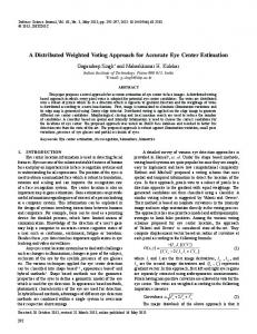
IV. Analytical Framework and Examples A trajectory of an aircraft is generated by selecting values for its degrees of freedom over a time horizon. This trajectory is required to abide by a set of constraints that are imposed to achieve certain ATM objectives such as maintaining separation requirements and balancing demand and capacity. Therefore, these constraints define a solution space for the aircraft consisting of the set of feasible trajectories. Out of these trajectories the aircraft selects one that optimizes its preferences, such as meeting company profit objectives by minimizing fuel burn, delay, discomfort, and other factors. In this section the functions of trajectory flexibility preservation and constraint minimization are posed in the framework of the trajectory solution space and its defining constraints. Since the primary focus of this paper is to describe the concept this is done at a preliminary level using limited-scope examples for the purpose of providing analytical insight into the concept. The trajectory solution space of an aircraft with RTA constraints at specific locations is investigated. The notion of trajectory flexibility and the effect of the RTA constraints and of conflict constraints on it are highlighted in this analytical framework. A. Trajectory solution space with multiple RTA constraints Figure 7 depicts a simple scenario of a single aircraft required to meet an RTA at a distance d along its path s, as shown in the right side of the figure. The RTA is to be met within a given tolerance in time t. The left side of the figure displays the trajectory solution space of the aircraft in an s-t space, assuming speed is its only available degree of freedom. The set of times that are reachable at any distance s are bound by traveling at maximum speed Vmax and at minimum speed Vmin. This set is reduced by the RTA tolerance requirement at distance d and the set of feasible trajectories is correspondingly reduced as shown in the figure by eliminating the non-feasible region. The nonfeasible region consists of the reachable states that, if reached, the full speed range is not effective in meeting the RTA tolerance. The remaining states are feasible in the sense that if reached at least one solution using speed exists to meet the RTA tolerance. Any trajectory that contains non-feasible states is infeasible in the sense that it violates the RTA constraint (Trajectory B in Figure 7) and any trajectory that does not contain any non-feasible states is feasible (Trajectory A in Figure 7). The set of feasible states is the convex hull bound by straight lines with slopes Vmin and Vmax drawn from the current state, a straight line with slope Vmax drawn through the later RTA tolerance end, and a straight line with slope Vmin drawn through the earlier RTA tolerance end.
8
s
Non-feasible region
d Vmax
s Fix
Feasible region
RTA
t
d
Trajectory B
Ó
Trajectory A
Vmin
t
RTA
Figure 7 Solution space with single RTA constraint Imposing more constraints further limits the trajectory solution space of the aircraft. For example, Figure 8 shows the effect of adding a second RTA constraint (RTA2) at distance d2 in addition to a constraint RTA1 at d1 > d2, along another aircraft path s1. RTA2 may result from a congestion region at distance d2 along s1, while path s that was analyzed in Figure 7 does not go through such congestion. The feasible region of the solution space is reduced dramatically to the set of trajectories that meet both RTA tolerances. For example, trajectory B which would be feasible in terms of meeting RTA1 before imposing RTA2 becomes infeasible because it does not meet RTA2. The feasible region between two successive RTAs is the convex hull between the following lines: Straight lines with slope Vmax drawn through the earlier tolerance end of the earlier RTA and the later tolerance end of the later RTA, straight lines with slopes Vmin drawn through the later tolerance end of the earlier RTA and the earlier tolerance end of the later RTA, and horizontal lines drawn at the distances d1 and d2. The feasible region is then the union of the feasible regions between the current state and the first RTA and between each successive pair of RTAs. s1 Non-feasible region
d1 s
Vmax
RTA2
t
d2
d1 Fix
s1
RTA1
t
Feasible region
Congestion
d2 Trajectory B
Ó
Trajectory A
Vmin RTA2
t
RTA1
Figure 8 Solution space with multiple RTA constraints If the location of RTA2 in Figure 8 is shifted to the right or left over time, or its tolerance is reduced, it is possible that no trajectories would be available that meet both RTA1 and RTA2. This occurs when no feasible region connects the aircraft current position to the destination RTA1. In this case the aircraft trajectory is over-constrained as mentioned in Section III and requires relaxation of some constraints. Therefore, as Figure 8 demonstrates, relaxing an RTA constraint by, for example, increasing the tolerance or changing the timing has a clear impact on opening up solution space and allowing more feasible trajectories.
9
B. Flexibility as accommodation of disturbances Given the solution space defined in Figure 7 or Figure 8 the aircraft selects a trajectory that meets all the imposed constraints, if not over-constrained. If the environment is deterministic the aircraft proceeds along the trajectory as predicted and the aircraft meets its objectives without violating any constraints. However, disturbances may occur that may alter the images depicted in these figures from what is predicted. The notion of trajectory flexibility is defined as the ability of the aircraft to accommodate such disturbances while abiding by the constraints. Disturbances may be classified into two types one related to the state of the aircraft and the other to the constraints that define the solution space: State disturbances result in deviations in the aircraft state from what is predicted by the trajectory. If some information is available about such disturbances they may be modeled into an envelope around the aircraft trajectory over the time horizon. For example, if the aircraft trajectory prediction was based on a wind speed model the imperfect information in the wind forecast may be modeled as a range on the ground speed and hence a range on the state of the aircraft at each time over the horizon of the trajectory prediction. Such a range typically grows over time. Constraint disturbances result in deviations in the constraints that define the solution space for the aircraft trajectory. These deviations may be in the form of introduction of new constraints or modifications in currently imposed/predicted constraints. For example, RTA2 in Figure 8 may be introduced as a disturbance to the situation depicted in Figure 7, thus drastically changing the solution space. Or, the RTAs may shift in time or change in tolerance relative to what was predicted, thus perturbing the boundaries of the solution space. Such disturbances may result from traffic flow management actions of which limited information is available at the time of prediction. Constraint disturbances include many types of constraints such as the introduction and movement of traffic and weather cells. To accommodate such disturbances the aircraft selects out of its solution space a trajectory that affords it sufficient flexibility. Two characteristics have been identified as relevant to measuring flexibility: robustness and adaptability. These characteristics are defined and demonstrated through example in order to illustrate the concept in analytical terms. The use of the robustness and adaptability characteristics to develop metrics and methods to preserve the flexibility of the aircraft in accommodating different types of disturbances is a topic of ongoing research which will be presented in future papers. 1. Robustness is defined as the ability of the aircraft to maintain its trajectory unchanged in response to the occurrence of a disturbance. A trajectory that can withstand a disturbance without having to change is more robust than other trajectories that become infeasible when the disturbance occurs. In the context of the RTA constraint scenario of Figure 8 and considering the introduction of RTA2 as a disturbance, a trajectory that remains feasible in terms of meeting the tolerances of both RTA1 and RTA2 despite the introduction of RTA2 (which significantly reduced the solution space) is robust. Therefore, referring to Figure 7 and Figure 8, in order to increase its robustness the aircraft may choose path s over s1, because it has a lower risk of the introduction of a second RTA. If for other reasons the aircraft selected path s1, then it may also select a trajectory within the solution space of Figure 8 that is more robust. For example, if the aircraft selected trajectory A instead of trajectory B prior to the imposition of RTA2, then the aircraft increases its robustness because if RTA2 is ever imposed the aircraft has low probability of needing to change its trajectory. The selection of trajectory A over B may be based on partial information indicating that RTA2 has a highest likelihood of occurring in the time window depicted in the figure. 2. Adaptability is defined as the ability of the aircraft to change its trajectory in response to the occurrence of a disturbance that renders the current trajectory infeasible. In the context of the multiple RTA scenario of Figure 8, if trajectory B was selected prior to the imposition of RTA2, it becomes infeasible once RTA2 is imposed. In order to adapt to such disturbance the aircraft can change its trajectory from B to A. The occurrence of RTA2 as depicted in Figure 8 although reduced the solution space left a set of feasible trajectories for the aircraft to be able to adapt. It is possible that RTA2’s timing and tolerance would not leave any feasible trajectory for the aircraft to adapt to it. Therefore, in order to increase its ability to accommodate such a disturbance the aircraft would select its path so as to maximize its adaptability to the extent possible. For example, with partial information that RTA2 may occur at the congestion area, the aircraft may select a path si (for example s1 in Figure 8) such that the reachable and otherwise feasible times at the congestion area location along si are maximized. In this case the probability that the occurrence of RTA2 blocks the whole solution space is reduced. C. Example with conflict as disturbance to meeting RTA In order to generalize the notions described in Section B another example is given that involves meeting RTAs and a conflict with moving traffic (or weather cells) as disturbance. Figure 9 shows an intruder aircraft that is expected to cross the aircraft path s1 between locations d3 and d4. The geometry and timing of the conflict translates into a conflict region in the s-t domain as shown in the left side of the figure. Idris et al. gives a mathematical
10
s1 Non-feasible region
d1 d4
s
Vmax
d3
RTA2
d1
t
d2 Feasible region
d3
Conflict region
Fix
s1
RTA1
t
d2
Trajectory B
Ó
Trajectory A
Vmin RTA2
d4
Ó
t
RTA1
Figure 9 Solution space with multiple RTA and conflict constraints formulation of this translation and the resulting conflict region shape for a circular separation zone around the intruder aircraft moving at a constant speed.21 In words: the circular separation zone occupies a line segment along s1 that starts as a point when the zone first touches s1 and grows in size to the length of the diameter and then shrinks to a point when the zone leaves the path s1. The resulting conflict region in the s-t domain is an elliptical shape with all points within corresponding to loss of separation. Any trajectory that crosses this region loses separation with the intruder and is hence infeasible. Figure 9 shows the combined impact of the RTA and conflict constraints on the solution space as the conflict cuts out additional infeasible regions. These regions are bound by the Vmax and Vmin tangents to the elliptical conflict region. Idris et al. gives closed form formulas for these tangency points.21 As shown in the figure trajectory B is infeasible because of loss of separation with the intruder aircraft (even in the absence of RTA2) while trajectory A remains feasible by meeting both RTAs and maintaining separation with the intruder aircraft. Similarly to the discussion in Section B, the aircraft may increase its robustness by selecting trajectory A that has less chance of changing as a result of the conflict, given any partial information about the likelihood timing and location of the conflict. The aircraft may also increase its adaptability by selecting a path with the largest set of reachable and otherwise feasible states around the predicted location and timing of the conflict. In this case if the conflict is predicted it has low probability of blocking all the otherwise feasible states. The example in Figure 9 demonstrates how the introduction of additional constraints, such as RTAs and conflicts, reduces the adaptability of the aircraft by blocking out parts of the maneuverability solution space. Conversely, relaxing these constraints, when possible without jeopardizing the intended ATM objectives, increases the adaptability and hence flexibility of the aircraft. For example, removing RTA2 in Figure 9 increases the size of the feasible region and reduces the chance that the prediction of the conflict renders the aircraft over-constrained or excessively constrained. The aircraft may also select path s, which has less probability of incurring the RTA2 constraint, over path s1 to achieve higher adaptability. The multiplicity of the constraints and their types also gives rise to a prioritization among them, which is important when the aircraft is unable to meet all of the constraints. For example, if the aircraft in Figure 9 is over-constrained, it may report to the traffic manager that it is unable to meet RTA2 (“Unable RTA2”) because of the conflict. In this case the traffic manager may relax RTA2 ensuring safety at the expense of less important objectives.
V. Concluding Remarks This paper described two new functions for the distributed ATM system that make up a trajectory-based approach to managing traffic complexity. A trajectory flexibility preservation function enables an aircraft to plan its trajectory such that it preserves a requisite level of flexibility in accommodating unforeseen disturbances, stemming for example from other traffic and from weather activity. A trajectory constraint minimization function enables ground-based agents, in collaboration with air-based agents, to impose just-enough constraints on trajectories to achieve ATM objectives, such as separation assurance and flow management. The concept hypothesizes that by each individual aircraft preserving its own trajectory flexibility, aggregate system objectives, such as maintaining acceptable traffic complexity (complexity defined as proneness to compromising safety), are naturally achieved. It also hypothesizes that minimizing the constraints imposed on a trajectory, without jeopardizing the intended ATM objectives, increases its flexibility.
11
The concept and its underlying hypotheses were illustrated through hypothetical scenarios involving conflict resolution and flow management. A functional analysis demonstrated the interaction and information flow between the functions schematically. The paper also described an analytical framework for defining metrics and developing methods to preserve trajectory flexibility and minimize its constraints. In this framework flexibility was defined in terms of robustness and adaptability to disturbances. Furthermore, the impact of constraints was illustrated through analysis of a trajectory solution space with limited degrees of freedom, namely speed variation along the aircraft path, and in simple constraint situations involving meeting multiple times of arrival and resolving a conflict. These notions, described conceptually and qualitatively in this paper, will be formalized and extended to other degrees of freedom and more general constraints/disturbance situations in future research.
Acknowledgments This research was funded by NASA under contract NNA07BA86C.
References 1
Joint Planning and Development Office, “Next Generation Air Transportation System Integrated Plan,” URL: http://www.jpdo.gov/library/NGATS_v1_1204r.pdf 2 Wing, D., “A Potentially Useful Role for Airborne Separation in 4D-Trajectory ATM Operations,” AIAA-20057336, 2005. 3 NASA, DAG-TM Concept Element 5 En Route Free Maneuvering for User-Preferred Separation Assurance and Local TFM Conformance Operational Concept Description, NASA Advanced Air Transportation Technologies Project Milestone 8.503.10, NASA Airspace Systems Program Office, Washington D.C., 2004. 4 NASA, DAG-TM Concept Element 11 Terminal Arrival Self-Spacing for Merging and In-Trail Separation Operational Concept Description, NASA Advanced Air Transportation Technologies Project Milestone 8.652.7, NASA Airspace Systems Program Office, Washington D.C., 2004. 5 Hill, J.C., Archibald, J.K., Stirling, W.C., and Frost, R.L., “A Multi-Agent System Architecture for Distributed Air Traffic Control,” AIAA-2005-6049, 2005. 6 Wollkind, S., Valasek, J., and Ioeger, T., “Automated Conflict Resolution for Air Traffic Management Using Cooperative Multiagent Negotiation,” AIAA-2004-4992, 2004. 7 Versteegt, H.H., and Visser, H.G., “Traffic Complexity Based Conflict Resolution,” AIAA-2002-4443, 2002. 8 Ballen, M., Sharma, V., Vivona, R., Johnson, E., and Ramiscal, E., “A Flight Deck Decision Support Tool for Autonomous Airborne Operations,” AIAA-2002-4554, 2002. 9 Mondoloni, S., and Conway, S., “An Airborne Conflict Resolution Approach Using A Genetic Algorithm,” AIAA-2001-4054, 2001. 10 Vivona, R., Karr, D., and Roscoe, D., “Pattern-Based Genetic Algorithm for Airborne Conflict Resolution,” AIAA-2006-6060, 2006. 11 Barhydt, R., and Kopardekar, P., “Joint NASA Ames/Langley Experimental Evaluation of Integrated Air/Ground Operations for En Route Free maneuvering,” 6th USA/Europe Air Traffic Management R&D Seminar, Baltimore, MD, 2005. 12 Krishnamurthy, K., Barmore, B., and Bussink, F., “Airborne Precision Spacing in Merging terminal Arrival Routes,” 6th USA/Europe Air Traffic Management R&D Seminar, Baltimore, MD, 2005. 13 Mediterranean Free Flight Programme Final Report, D821, http://www.medff.it/public/index.asp, November 2005. 14 Sridar, B., Sheth, K., and Grabbe, S., “Airspace complexity and its application in air traffic management,” 2nd USA/Europe Air Traffic Management R&D Seminar, Orlando, FL, December 1998. 15 Delahaye, D. and Puechmorel, S., “Air traffic complexity: towards intrinsic metrics,” 3rd USA/Europe Air Traffic Management R&D Seminar, Napoli, Italy, June 2000. 16 Histon, J.M., Aigoin, G., Delahaye, D., Hansman, R.J., and Puechmorel, S., “Introducing structural considerations into complexity metrics,” 4th USA/Europe Air Traffic Management R&D Seminar, Sante Fe, NM, December 2001. 17 Delahaye, D. Puechmorel, S., Hansman, R.J., and Histon, J., “Air traffic complexity based on non linear dynamical systems”, 5th USA/Europe Air Traffic Management R&D Seminar, Budapest, Hungary, Jume 2003. 18 Kopardekar. P. and Magyarits, S., “Measurements and prediction of dynamic density,” 5th USA/Europe Air Traffic Management R&D Seminar, Budapest, Hungary, Jume 2003. 19 Riley, V., Chatterji, G., Johnson, W., Mogford, R., Kopardekar, P., Sierra, E., and Lawton, G., “Pilot perceptions of airspace complexity, part 2,” DASC 2004.
12
20
Coppenbarger, R., Lanier, R., Sweet, D., and Dorsky, S., “Design and Development of the En Route Descent Advisor (EDA) for Conflict-Free Arrival Metering,” AIAA-2004-4875, 2004. 21 Idris, H., Hsu, T., Vivona, R., and Green, S., “Time Based Conflict Resolution Algorithm and Application to Descent Conflicts,” AIAA GNC conference, Austin, TX, August 2003.
13