Towards Safety Analysis of Highly Integrated Technologically Heterogeneous Systems – A Domain-Based Approach for Modelling System Failure Logic O. Lisagor; Department of Computer Science, The University of York; York, UK M. Pretzer; Kuratorium OFFIS e.V.; Oldenburg, Germany Dr. C. Seguin; Centre de Toulouse, ONERA/DTIM/CVSI; Toulouse, France Dr. D. J. Pumfrey; Department of Computer Science, The University of York; York, UK Dr. F. Iwu; Department of Computer Science, The University of York; York, UK T. Peikenkamp; Kuratorium OFFIS e.V.; Oldenburg, Germany Keywords: safety assessment, technological heterogeneity, failure logic modelling, formal safety models, compositional modelling, failure transformation Abstract This position paper from the Airbus Dependability Network (a strategic research partnership between Airbus and three leading European research institutions in the field of system safety) outlines an approach to modelling and safety analysis of technologically heterogeneous systems. The approach builds upon the idea of modelling failure propagation and transformation in a system. These failure behaviour models are extended by introducing a notion of modularity with respect to underlying technology (“domains”). This allows flexibility in the modelling and assessment of individual, technologically homogeneous components (“domain-specific failure logic models” – DSFMs) whilst providing a structure that facilitates the integration of these component models to represent complete system behaviour. The approach also facilitates incremental analysis of the system, whereby DSFMs can be subjected to analysis, such as Fault Tree Analysis, first individually, and then in combination as composition of models progresses. The paper concludes with an outline of the work necessary for implementing the approach as a practicable safety assessment methodology and a discussion of how the methodology can be utilised throughout the development process to maximise the added value. Introduction The increasing complexity of safety critical systems has been recognised as a challenge to traditional safety analysis and modelling methods for some time. System complexity has usually been interpreted as a combination of the number of components, the behavioural complexity of individual components (e.g. the complexity of computations performed, the state-space of the component, real-time features, etc.) and the degree of coupling between the components. Numerous approaches to modelling systems that exhibit such types of complexity, as well as to performing safety analysis of these models, have been proposed. However, increasing complexity has another facet that, until recently, has not been explicitly studied in detail – the increased technological heterogeneity of modern systems. Each system on, for example, a modern civil aircraft may combine numerous types of components – mechanical, hydraulic, electrical, electronic, software, etc. – to achieve the required functionality. This heterogeneity poses significant challenges to the task of safety assessment. Dissimilarity of technology usually implies different teams of engineers and design specialists, working with dissimilar design tools, notations and methods. This means that there is rarely a fully integrated system model, and safety analysts must consult with numerous teams of engineers in order to gather all the information necessary for a safety assessment. Additionally, different technologies are prone to dissimilar types of failures, and it is very difficult to define a uniform vocabulary
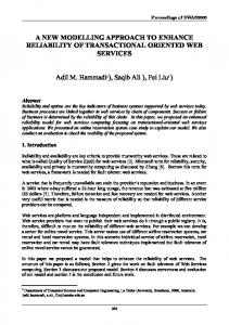
with the expressive capability to accurately describe the behaviour of technologically heterogeneous components in the presence of failures. The traditional practical solution to these problems is to divide system designs into technologically homogeneous parts and to model and analyse these parts separately. The interdependencies between the separate models are then investigated, and the whole system is also subjected to common cause and common mode failure analyses. As the models are not integrated, the analysis of interdependencies is typically very time consuming, extremely labourintensive and error-prone. Furthermore, as modern systems become more tightly integrated, this “divide and conquer” approach is becoming increasingly expensive and less acceptable. Failure Logic Models: The approach proposed by the authors builds upon the idea of failure logic models (sometimes also referred to as “failure propagation models” (ref. 1) or “formal safety models” (ref. 2)). These models have emerged as the increasing number of components in typical safety critical systems has made “one step” analysis of complete systems increasingly infeasible. Failure logic models facilitate a compositional approach: they allow analysts to characterise the behaviour of individual components in presence of failures, and then combine the component models to yield a system level failure logic model. Fault trees or FMEA tables can be automatically extracted from the combined models. The numerous concrete methods embodying this approach to safety assessment include Failure Propagation and Transformation Notation (FPTN) (ref. 1), Hierarchically Performed Hazard and Operability Studies (HiP-HOPS) (ref. 3) and the AltaRica modelling language (ref. 4). The former two approaches allow Boolean operations over failure modes. The latter approach allows component behaviour to be characterising using state machines in addition to combinatorial formula, and permits the use both nominal variables and failure modes in the models. While FPTN has remained largely an academic prototype, both HiP-HOPS and AltaRica have attracted significant industrial interest (especially from the automotive and aerospace industries). Overview of the Approach: Despite its advantages, Failure Logic Modelling is not readily applicable to complex systems exhibiting tight coupling between components implemented using dissimilar technologies. The main problem in modelling such systems is that fundamentally dissimilar vocabularies of failure modes are required to describe the behaviour of the different technologies. We propose extending failure logic modelling with a new type of modularity – modularity with respect to underlying technologies – which we call “domains”. Whilst retaining the uniform overall structure of a failure logic model, within each domain analysts may define a local vocabulary of failure mode types (“domain-specific failure mode vocabulary”) to allow intuitive representation of the actual behaviour of the technology. To construct a system failure model, domain specific failure logic models (DSFMs) must be first defined by safety analysts in consultation with appropriate design engineers. Individual DSFMs can be then combined together to (gradually) yield a system wide model. This integration requires “translation components” – notional components that link individual DSFMs and translate between local vocabularies of failure types. This approach allows flexibility in the modelling and assessment of individual, technologically homogeneous components, whilst providing a structure that facilitates cost-effective integration of these component models to represent complete system behaviour. It also facilitates incremental analysis of the system, as traditional analysis artefacts (e.g. Fault Trees and FMEA tables) can be extracted first from individual DSFMs and then from integrated DSFMs as composition of models progresses. This reduces the need for separate analysis of interdependencies, as this becomes seamlessly integrated into the modelling approach. Running Example We illustrate the proposed approach and its key concepts using the hypothetical aircraft braking system described in Appendix L of Aerospace Recommended Practice ARP-4761 (ref. 5). Figure 1 shows the system architecture. The main function of the system is to provide wheel braking as commanded by the pilot when the aircraft is on the ground. The system is highly redundant: it utilises redundant hydraulic supplies (“green” and “blue”), redundant electrical power supplies and two redundant controllers (with monitoring capabilities in each). The intent of this redundancy is to enable the system to deliver its intended function in the presence of any foreseeable single failure.
AS 1
CDM / AS 1
Command 1
Normal AS 2
Anti Skid (AS) Command (CMD) / Anti Skid
Braking System Control Unit (BSCU)
Selector Valve
Anti Skid Shut Off Valve Meter Valve Meter Valve
Isolation Valve Alternate
Pedal Position 2
Power 2
Command 2 CDM / AS 2
Blue Pump Shut Off Selector Valve
Monitor 2
2 Invalid
1 Invalid
Pedal Position 1
Power 1
Monitor 1
Green Pump
Reserve
Accumulator
Mechanical Pedal Position
Wheel
Figure 1 — Architecture of the Braking System (reproduced from (ref. 5)) Normally (in the absence of failures), the demand for braking is determined either by the position of the brake pedals in the cockpit or by a value preset by the pilot. This is converted by the Braking System Control Unit (BSCU) into electrical signals to a meter valve on the green hydraulic line that, eventually, powers the wheel brakes. Although the BSCU has two primary outputs – CMD and AS – only CMD is used in the normal mode (i.e. both braking demand and anti skid adjustment are “blended together”). The BSCU is internally redundant and consists of two (individually monitored) channels. Upon a single failure, control is handed over from the first channel (Command 1) to the second (Command 2) with no effect on the mode of operation of the whole system. However, if both monitors report failure the BSCU is deemed inoperable and is shut down, and the green hydraulic line is cut off. This triggers the hydraulic system to switch over to the alternate mode, powered by the blue hydraulic pump (backed up by the hydraulic pressure accumulator). The alternate mode can also be triggered by insufficiently high pressure from the green pump. The switch over is carried out by the pressure-triggered selector valve. In alternate mode, braking demand is solely set by the position of the pedals, which are mechanically linked to the meter valve. If the BSCU is still operational (e.g. alternate mode was selected due to a failure of the green pump) its function is reduced to anti skid only. It is important to note that Figure 1 shows a high-level schematic of the system with much detail omitted – readers are referred to the source (ref. 5) for details of the BSCU implementation. However, it is sufficient to illustrate key elements of the approach. Domains and Local Vocabularies The system clearly employs numerous technologies. Figure 1 itself can be crudely divided into 4 domains: computer/digital, electrical, hydraulic and mechanical (figure 2). If more detailed design models are considered, then more technologies (and, thus, domains) emerge. For example, the computer-based controllers could be divided into three further domains: digital hardware, operating system software and application software. Similarly, the electrical domain in Figure 2 could be further divided into “electrical power” and “electrical control” depending on the purpose for which the current is provided. Domain boundaries are determined by attributes, including the purpose of the flows in the domain (e.g. do interconnections in the design model represent the movement of information, energy or material), the physical nature of flows (electricity, pressurised fluid, data, mechanical motion, etc.) and the model of time assumed (discrete or continuous). For convenience, domains may also be used to delimit the work of different design teams, or particular engineering skills that are necessary for designing (groups of) components.
HYDRAULIC
Green Pump Shut Off Selector Valve Normal
2 Invalid
Monitor 2
Command 2 CDM / AS 2
AS 2
Anti Skid (AS) Command (CMD) / Anti Skid
Braking System Control Unit (BSCU)
Blue Pump
Selector Valve
Anti Skid Shut Off Valve
Isolation Valve Alternate
Pedal Position 2
Power 2
Pedal Position 1 AS 1
Command 1 CDM / AS 1
COMPUTER / DIGITAL
Monitor 1
1 Invalid
Power 1
ELECTRICAL
Reserve
Meter Valve Meter Valve
Accumulator
Mechanical Pedal Position
Wheel MECHANICAL
Figure 2 – Key Domains in the Braking System The implementation technology not only determines the normal behaviour of components, it also affects how they may fail and how their actual behaviour can deviate from the intent. We call a deviation of behaviour of a particular flow from its intended behaviour a Failure Mode (FM). One of the main goals of defining domains is to divide the system design into parts for which coherent vocabularies of failure mode types can be defined. Table 1 shows an (informally defined) vocabulary of failure mode types for the hydraulic domain. These failure mode types can be contrasted with the failure mode types of the electrical domain such as: CurrentTooHigh, CurrentTooLow, CurrentOmission, CurrentComission, CurrentExceptionallyHigh etc. Table 1 – Domain-Specific Failure Mode vocabulary (Hydraulic Domain) Hydraulic Domain Failure Mode Type PresTooHigh PresTooLow PresTooLate PresTooEarly RapidIncreasePres RapidDecreasePres NoChangePres FalseIncreasePres FalseDecreasePres PresOmission PresCommission TempTooHigh
Description Hydraulic pressure is higher than required Hydraulic pressure is lower than required Correct pressure is reached later than required Correct pressure is reached earlier than required / expected Pressure increases more rapidly than required / expected Pressure decreases more rapidly than required / expected Pressure doesn’t change when change is required Pressure increases when not required / expected Pressure decreases when not required / expected Pressure is not conveyed when required Pressure is conveyed when it should be blocked The temperature of the fluid is higher than required
Domain Specific Failure Logic Models Now that we have introduced the notion of domains and domain-specific failure mode types, we focus on a single domain specific failure logic model – for the hydraulic domain. In this section we will focus on valves – as we will show in the next section, these components lie on the interface between the hydraulic and electrical domains (or, in the case of the meter valve in the blue hydraulic line, between the hydraulic and mechanical domains). Component characterisation: A domain-specific failure logic model (DSFM) shows how failure modes are caused by components’ internal failures, how they propagate to other components (within the domain), and how they cause – or combine to cause – other failure modes. Characterisation of each component consists of a number of standard sections: o First, the sets of Output Failure Modes (OFM) and Input Failure Modes (IFM) list the possible deviations the component propagates via its output channels and receives via its input channels respectively. Consider the Shut Off Selector Valve in the green hydraulic line in the braking system. The valve belongs to the hydraulic domain. It has one output (“out”) and one input channel (“in”), both belonging to the hydraulic domain. Both input and output are potentially associated with all the failure modes listed in the table 1 above. Therefore, OFM := { out.PresTooHigh, out.PresTooLow, …} and IFM := { in.PresTooHigh, in.PresTooLow, …}. o Second, the set of Internal Failures (IF) lists the abnormal events (failures) that may occur spontaneously inside the component. For example, the shut off valve might open or close spontaneously, jam or heat up; thus IF := {OpensSpontan, ClosesSpontan, Jam, HeatsUp}. o While some failures might simply be propagated by a component without actually affecting it, others can cause temporary or permanent changes in the component. To capture this, we use a finite set of Failure States (FS), such as {OK, STUCK, BROKEN} for the shut off valve. o Finally, although the focus of these models is the failure logic of components, it might be necessary to include some nominal behaviour (such as fundamental nominal states/modes of the component). This is done by specifying a finite set of Functional States (FunS) which contains the states necessary to correctly specify the failure behaviour. Considering our valve, the propagation of input failures such as PresTooHigh clearly depends on the fact, whether the valve is actually Open or Closed. Based on these building blocks, the failure behaviour of a component can be described using failure propagation equations. For example, equation (1) below states that when the input pressure is too high the output pressure will also be too high, provided the valve is actually open. Equation (2) states that, provided that input pressure is available, the spontaneous opening of the valve while it should remain closed leads to superfluous output pressure. A more complete characterisation of the Shut Off Selector Valve is shown on the left hand side of Figure 3. {FS=ok; FunS=Open; IFM=in.PresTooHigh} Æ {OFM=out.PresTooHigh} {IF=OpensSpontan; IFM=not(in.PresOmission) } Æ {OFM=out.PresComission}
(1) (2)
Once each component in the domain is characterised, the components can be linked together in order to yield the domain-specific failure logic model (DSFM) – we call this process “model composition”. Model composition within one domain: Due to the single vocabulary of failure mode types, model composition within one domain is relatively straightforward. It consists mainly of identifying the links (flows) between the individual components in the design model and linking corresponding input and output failure modes to reflect propagation between the components. In most cases, the failure mode links between components in DSFMs directly correspond to the channels found in the actual system models. However, it is important to note that flows in design models often correspond to bi-directional flows of Failure Modes. Indeed, a reversed direction of flow (e.g. of hydraulic fluid) is a typical failure mode type. Consider, for example, the failure of the Isolation Valve to separate the Blue Pump from the Accumulator when the pump is stopped. This may result in a reverse flow of hydraulic fluid (potentially draining the downstream system of necessary fluid) and in an undue pressure being applied to the pump itself (potentially causing permanent damage). The right hand side of Figure 3 shows bi-directional propagation of failure modes through the hydraulic system. However, we omit this from the valve characterisation on the left hand side due to space limitations.
From Green Pump To Selector Valve
Figure 3 – DSFM for hydraulic domain and characterisation of the Shut-Off Selector Valve component Finally, we propose that functionally passive components (pipes, wires, etc) should normally be explicitly modelled in DSFMs as components in their own right. This is because these components can develop internal failures (leaks, short circuits, etc.) and are important from the safety and reliability points of view. However, the equations associated with functionally passive components are normally relatively simple and can be reused throughout the DSFM concerned. Again, pipes are omitted from Figure 3 due to space limitations. DSFM composition So far, we have only considered construction of a single DSFM. However, in order to perform a system safety assessment, it is necessary to integrate the DSFMs of different domains into one “global” failure logic model. We illustrate how this is achieved by linking the characterisation of the Shut Off Selector Valve to the two-core cable used to connect the BSCU monitors to the valve (Figure 2). As a functionally passive component, the cable propagates most of its input failure modes directly to the output with no transformation. However, failure of the insulation between the cores could lead to a short circuit (failure state). We have also introduced a special failure mode into the electrical system model to represent abnormally high current (e.g. generated by a short circuit) – Current Exceptionally High. We can now consider how the electrical and hydraulic DSFMs can be integrated. We assume that the valve is normally closed, and opens when power is supplied. Clearly, the valve is not only sensitive to the hydraulic failure modes but also to failure modes it receives via the cable. For example, provision of electrical current when not required (CurrentComission) will cause the valve to output hydraulic pressure when not required. One way of modelling this would be to revisit and change (wherever appropriate) the existing characterisation of the valve. However, this would undermine the compositionality property of our models as the amended characterisation of the component could not be reused elsewhere in a different context. Instead, we accommodate the new failure mode flows by a new section in the component characterisation – “DSFM Integration” (Figure 4).
Furthermore, we observe that failure modes “imported” by a component from other domains (i.e. via inputs not belonging to the component’s own domain) may represent causes of the component’s “internal” failures. For example, if the hydraulic domain is considered in isolation, the behaviour under commission of electrical current will look like the valve opening spontaneously. So, two subsections of “DSFM Integration” are Input Failure Modes (listing failure modes imported from other domains) and Input Equations (linking these new failure modes to existing internal failures of the component). In our valve example, two of the imported FMs are: CurrentCommission and CurrentExceptionallyHigh; these become causes of OpenSpontan and HeatsUp failures. Now, recalling our earlier comments about bi-directionality of failure mode flows, we observe that malfunctioning of the valve may affect the electrical components to which it is connected. For example a stuck valve may draw an excessive electrical current, thus exporting a failure mode back to the electrical cable. Therefore, we need to add two more subsections to “DSFM Integration” – Output Failure Modes and Output Equations.
Figure 4 – Integration of components belonging to different domains It is important to note that modelling FM propagation from valve to the electrical domain now allows us to capture the causal relationship between valve the jamming and it heating up, and thus heating up the hydraulic fluid. This relationship can clearly be important from the safety perspective. More importantly, the model allows analysts to suggest strategies for breaking the dependency (e.g. adding a fuse to the circuit, and/or designing valve so that the motor disconnects from the valve if the reaction force exceeds certain level). Let us now investigate some other – less direct – dependencies between the hydraulic and electrical domains. Consider a short circuit in the cable. This could result in a fire which in turn may heat the valve up. This failure mode propagation could be modelled directly, but we consider this approach unintuitive and somewhat crude. Instead, we observe that, in addition to the domains identified in Figure 2, the physical layout of components can be considered as a further domain. The components in the physical domain represent partitioning of the system (e.g. aircraft) into zones. We can now use this domain to model the fact that once a fire occurs, it affects all of the components in a zone by heating them up, and that heat and fire can also propagate from one zone to another. Figure 5 shows the propagation of fire and heat from the cable to the valve (and potentially other components). Failure modes represented in the zonal domain are “Fire” and “ExcessiveHeat”. We assume that the cable and the valve are in “Zone 1”. The valve imports ExcessiveHeat from zone 1 resulting in the HeatsUp internal failure. Similarly the cable both exports Fire (derived from its ShortCircuit failure state) to zone 1 and imports it from the zone (converting it to the LosesInsulation internal failure). Note that a leak from a valve (potentially causing a short circuit) clearly can be modelled in a very similar way.
Figure 5 – Failure Mode Propagation through the Zonal Domain We now have a powerful approach for modelling common causes of failures of multiple components which is seamlessly integrated with the rest of the approach. For example, in conjunction with the earlier integration between the electrical and hydraulic domains, we would be able to see from the failure logic models how, if a valve does not have an electrical fuse, the valve jamming may result in a fire, and how this fire would affect other components nearby. Future Work – From Vision to the Complete Approach The approach presented in this paper is at early stage of development. The authors are now experimenting with the proposed concepts and defining clear methodological guidance. This section outlines the key characteristics of – and extensions to – the basic approach that are being investigated. DSFM Composition and Translation Components: In the sections above, we presented a rather naïve approach to DSFM composition. Indeed, if individual DSFMs (and corresponding vocabularies of failure mode types) are constructed independently it is not unlikely that there will be fundamental “mismatches” between the strategies (“philosophies”) employed that could not be resolved within the “DSFM Integration” sections of individual component characterisations. This means that DSFM composition will require a mechanism for translation between the “worlds” of different domains (e.g. where different notions of time have been employed). Such translation can be done within dedicated notional components, placed between individual DSFMs. These translation components can be specified using the same language as for ordinary component characterisation (although translation components would not have any “internal failures”). The authors are currently experimenting with alternative ways of specifying these components and using them for DSFM composition. Domain Boundaries: In this paper, the authors have focussed on domains as a facility to divide system assessment into more technologically homogeneous parts. However, the fundamental idea behind domains is that a time- and cost- effective safety assessment process has to reflect the design process. Coherent parts of the design should be analysed as and when they emerge. Thus, the boundaries of domains are not set by safety analysts – they should reflect separation of responsibilities over the design between different teams of engineers, design schedules, etc. Furthermore, the authors believe that the notion of domains can be easily extended to include “process domains”. For example, we are investigating the feasibility of defining “supplier domains” (to differentiate the responsibilities of external suppliers and internal teams of engineers) and “unique component domains” (to capture the use of identical equipment in different parts of the system). Such domains will facilitate the identification of common causes and modes of failures of seemingly independent components. “Physical” domains: The domains that the authors have considered so far are characterised by flows (e.g. of electrical current, hydraulic pressure, data, etc) between distinct components. Both flows and components in our model are assumed to be discrete and somewhat “atomic”. That is, components (at the lowest level of decomposition) have clearly defined boundaries and perform a transformation of flow characteristics as a whole.
Similarly, the functionally passive components that carry flows have boundaries and normally (i.e. in the absence of failures) transfer values from source to destination components without change. In the long term, the authors are planning to investigate whether the modelling approach, and the notion of domains, can be extended to include physical phenomena such as heat conduction, mechanical stress and loads etc. These phenomena are characterised by flows whose properties may change with time or distance (e.g. temperature gradients through a conductive material as a function of distance from the heat source) and continuous components (e.g. spaces or surfaces). Capturing these models and integrating them into failure logic modelling is important in order to correctly account for failure propagation through the geometry of a system. If it proves possible to successfully integrate these physical characteristics, it will become possible to further automate common cause analyses, promising further cost reductions and improved accuracy of safety analysis. Conclusions This position paper has presented an approach to safety assessment of modern highly integrated technologically heterogeneous systems. The approach is currently at an early stage of definition, but it builds upon mature research in failure logic modelling that is being increasingly adopted by industry. The approach extends traditional failure logic modelling methods with the goal of adapting them to the needs of a modern industrial process. Such processes are characterised by different parts of the design emerging at different times in the development process, and being allocated to different teams of engineers who may employ diverse (design) modelling and analysis techniques. The approach facilitates compositional modelling and incremental analysis is a number of ways. First, and somewhat outside the scope of this paper, we are implementing refinement relations and abstraction operations on the models and components. This will allow analysts to refine failure logic models as design models themselves are refined and become more mature. Thus, it will be possible to obtain an early insight into the safety characteristics of a proposed design before design work is complete, and while changes to the design would incur smaller costs. At the same time, the abstraction operation will allow analysts to generate analysis (e.g. Fault Trees) at a manageable level, and with a meaningful hierarchy, even when final (i.e. very detailed) models are defined. Second, the ability to define and analyse each single Domain-Specific Model individually, and then to perform analysis iteratively as DSFM integration continues, will allow safety assessment to follow the development process in the most effective way. The approach will ensure that partial analysis (e.g. FTA, FMEA) is performed as soon as possible and feedback is given to teams of design engineers at the earliest opportunity (i.e. with no need to delay the feedback pending completion of other parts of the design). In common with the approaches we build upon (refs. 1, 3, 4), the models proposed in this paper will allow for automated generation of traditional safety assessment artefacts (Fault Trees, Dependence Diagrams, FMEA tables) utilising existing, well-publicised and quite mature methods. The preliminary definition of the approach partially presented in this paper has been undertaken by researchers in OFFIS, ONERA and the University of York and evaluated “in principle” by safety specialists in AIRBUS as part of the ongoing Dependability Network project. It is planned that further investigations (including of the issues outlined in this paper), detailed method definition and formulation of necessary methodological guidance will be undertaken as part of a larger European-wide project that will include research institutes and industrial partners. Acknowledgements Authors would like to thank their colleagues who have contributed to the preliminary research this paper is based on: Prof. Werner Damm (OFFIS), Dr. Pierre Bieber (ONERA) and Prof. John McDermid (University of York). We would also like to thank AIRBUS Industries for funding that enabled this research, for review of the results and many useful discussions. In particular we would like to thank Dr Chris Papadopoulos (AIRBUS UK), Mr Matthias Maruhn (AIRBUS Deutchland) and Mr Martin Dobson (AIRBUS UK) for reviewing drafts of this paper and for their invaluable comments.
References 1.
P Fenelon, et al, Towards Integrated Safety Analysis and Design, In ACM Applied Computing Review, 2(1):21-32, 1994, ACM Press.
2.
Ch. Kehren, et al, Advanced Simulation Capabilities for Multi-Systems with AltaRica, in Proceedings of the 22nd International System Safety Conference (ISSC), 2004, System Safety Society.
3.
Y. Papadopoulos, et al, Analysis and Synthesis of the Behaviour of Complex Programmable Electronic Systems in Conditions of Failure, Reliability Engineering and System Safety, 71(3):229-247, 2001, Elsevier Science.
4.
A. Griffault, et al, The AltaRica Formalism for Describing Concurrent Systems, in Fundamenta Informaticae, 1999, IOS Press
5.
Society of Automotive Engineers Inc, Aerospace Recommended Practice (ARP) 4761: Guidelines and Methods for Conducting the Safety Assessment Process on Civil Airborne Systems and Equipment, December 1996. Biographies
O. Lisagor, Research Associate, HISE Group, Computer Science Department, The University of York, Heslington, York, YO10 5DD, UK, telephone – +44 1904 434728, fax – +44 1904 432708, e-mail –
[email protected]. Oleg Lisagor is a research associate at the University of York, working within the HISE group. He received a Masters of Engineering degree from York in 2002 and is currently pursuing a doctorate degree. His research interests lie in the general area of novel methods for analytical system safety analysis and safety-related modelling. M. Pretzer, Kuratorium OFFIS e.V., Escherweg 2, 26121 Oldenburg, Germany, telephone – +49 441 9722533, fax – +49 441 9722502, e-mail –
[email protected] Matthias Pretzer is a research assistant at OFFIS, working in the R&D division Safety Critical Systems. He received a diploma with honours in Computer Science from Oldenburg in 2005. His research interests lie in the formal verification of safety critical systems and in the application of formal methods to safety analysis. C. Seguin, Ph.D., ONERA/DTIM/CVSI, Centre de Toulouse, 2 avenue E. Belin, F-31055 Toulouse Cedex 4, FRANCE, telephone – +33 5 62252642, fax – +33 5 62252593, email –
[email protected] Dr Christel Seguin has been a research engineer at ONERA (French public research centre for aeronautics and space) since 1992. She is working on the usability of various formal methods for assessing embedded safety critical systems. D. J. Pumfrey, D.Phil., Teaching and Research Fellow, HISE Group, Computer Science Department, The University of York, Heslington, York, YO10 5DD, UK, telephone – +44 1904 432735, fax – +44 1904 432708, e-mail –
[email protected]. Dr. David Pumfrey teaches on MSc and Certificate programmes in System Safety Engineering at the University of York. His research interests include methods of predictive safety analysis to help guide the early stages of design of critical systems, and new techniques for investigating hardware/software interactions in complex computer systems. F. Iwu, Ph.D., Research Associate, HISE Group, Computer Science Department, The University of York, Heslington, York, YO10 5DD, UK, telephone – +44 1904 433386, fax – +44 1904 432708, email –
[email protected] Dr. Frantz Iwu is a research associate in the High Integrity Systems Engineering group (HISE) in York. His current research interests include incremental development of methods and tools, which highlight the effective integration of safety analysis and system & software development methods and fault diagnosis and analysis in complex computer systems.
T. Peikenkamp, Kuratorium OFFIS e.V., Escherweg 2, 26121 Oldenburg, Germany, telephone – +49 441 9722525, fax – +49 441 9722502, e-mail –
[email protected] Thomas Peikenkamp is member of R&D division Safety Critical Systems, where he is working on model-based safety assessment methods for transportation systems.