A Dual-Sensor Enabled Indoor Localization System with Crowdsensing Spot Survey Chi Zhang
Nanyang Technological University, Singapore Email: {czhang8, junluo}@ntu.edu.sg
Abstract—We present MaWi - a smart phone based scalable indoor localization system. Central to MaWi is a novel framework combining two self-contained but complementary localization techniques: Wi-Fi and Ambient Magnetic Field. Combining the two techniques, MaWi not only achieves a high localization accuracy, but also effectively reduces human labor in building fingerprint databases: to avoid war-driving, MaWi is designed to work with low quality fingerprint databases that can be efficiently built by only one person. Our experiments demonstrate that MaWi, with a fingerprint database as scarce as one data sample at each spot, outperforms the state-of-the-art proposals working on a richer fingerprint database. Keywords—Indoor Localization, Mobile Sensing
I.
Jianxin Wu
Jun Luo
I NTRODUCTION
As increasing urbanization forces people to stay more often at indoor environments, locating and navigating people in complex constructions (e.g., airports and shopping malls) becomes a crucial problem. Furthermore, government and business also benefit from accurate user location information in precise information pushing. Luckily, rapid spread of high performance smart phones and wide 3G/Wi-Fi network access have caused an explosion of mobile sensing applications. Since smart phone has become an indispensable device in people’s daily life, an indoor localization service through smart phone sensing can be handily deployed without extensive efforts. To address the challenge of indoor localization, many systems have been proposed in recent years [1], [2], [3], [4], [5], [6]. However, smart phone based systems achieving both scalable and high accuracy are still missing. On one hand, while high accuracy has been achieved by some fingerprint-based (or empirical) systems [1], [2], they share the common prerequisite to entail heavy labor in building fingerprint database (a set of spots with associated signal fingerprints). Such a laborious spot survey process hinders the scalability in deployment. On the other hand, model-based systems [3], [4], [5], [6] avoid the spot survey by using propagation model to infer distances and trilateration to locate users. Unfortunately, these systems have either low accuracy [3] or high computational/infrastructrual demand: [4] requires the knowledge of the distances between all users and all Wi-Fi access points (APs) to computes a single user’s location; [5] demands software access to all APs; and [6] relies on a deployment of dedicated acoustic beacon. Because spot survey (deemed necessary for achieving high accuracy) hampers scalable deployments, crowdsensing is inThis work was supported in part by the AcRF Tier 1 Grant RGC5/13, AcRF Tier 2 Grant ARC15/11, and Nanyang Centre for Underground Space, NTU.
Nanjing University, Nanjing, China Email:
[email protected] troduced by recent proposals [7], [8], [9], [10] to distribute the intensive labors to a crowd. Whereas such technologies make large deployment possible, opportunistic spot survey cannot warrant fingerprint quality: insufficient samples at spots and low density in sampled spots are both potential problems, which could result into low accuracy in localization. In this work, we propose MaWi, a crowdsensing spot survey based indoor localization system. MaWi makes use of both Magnetic field and Wi-Fi signal as fingerprints. Because these two types of fingerprints have nice complementary performance in locational discrimination while magnetic field has an outstanding temporal stability, they should be used in a “duet” manner such that they offset the weaknesses of each other and thus improve their respective effectiveness. Through a smart combination of these two types of fingerprints, MaWi imposes a rather low demand on the volume of its fingerprint database. Therefore, MaWi achieves a scalable deployment by employing crowdsensing without intensive spot survey, while getting very competitive localization accuracy compared with state-of-the-art systems. Our major contributions in designing MaWi are: 1) We analyze properties of Wi-Fi signal and ambient magnetic field, and we, for the first time, identify their complementarity in indoor localization. 2) We present a scalable indoor localization system with crowdsensing spot survey process, MaWi, aiming to reduce the deployment cost for better scalability and to achieve high localization accuracy. 3) We deploy MaWi in large indoor areas with complicated floor plans, and our extensive experiments demonstrate a low deployment workload and high localization accuracy. We organize the subsequent sections as follows. We first study the complementary natures of Wi-Fi signal and ambient magnetic field as localization fingerprint in Section II. Basing on our studies on Wi-Fi signal, we formulate zone discrimination problem and propose an algorithm to address it in Section III. Then we present the main idea and design of MaWi in Section IV. In Section IV-H, we discuss the system structure of MaWi in detail, along with other implementation issues. Our extensive experiments are reported in Section V, before concluding this paper in Section VII. II.
F INGERPRINT S TUDIES
In this section, we present our studies on Wi-Fi and Magnetic field in both time and space dimensions. This serves as the major motivation of our proposal. Our test region is an 800 m2 office area shown in Figure 1.
L3
L2
L1 19 m
L5
61 m
Fig. 1.
Test region for fingerprint studies.
A. Wi-Fi Signal According to [11], two main factors hamper localization accuracy of fingerprint-based systems: 1) similar signals at multiple locations, and 2) transient measurement of signals at the same location. High signal similarity reduces locational discrimination, and transient measurement weakens the ability of properly classifying on-line observed fingerprints. While the former is caused by particular deployment of APs and indoor structures, the latter mainly attributes to limitations of measuring devices. Our studies intend to reveal how exactly a Wi-Fi localization approach is affected by these two factors. To the best of our knowledge, no extensive study has been performed in this aspect. Following conventions, we define WiFi fingerprint as a vector of RSSs (Receive Signal Strength) from detectable APs, easily measurable by smart phones, and we measure similarity by negative Euclidean distance. 1) Single Concurrent Sample per Spot: We evaluate the fingerprint similarity with respect to the number of APs in Figure 2. Color temperature is proportional to the fingerprint similarity between the location marked by the pentagram and the remaining area. Interfered by indoor construction, the area bearing similar fingerprints (the red area) for one AP appears like an irregular ring. With the increase of APs, the red area shrinks to a small zone nearby the pentagram. This experiment shows that given sufficient APs, similar fingerprints are prone to be observed in close-by location. Therefore, we may effectively tell two distant locations from each other using Wi-Fi fingerprints.
1 AP
3 AP
5 AP
20 AP
Fig. 2. Fingerprint similarity with one sample per spot given different numbers of APs.
2) Multiple Samples per Spot: Since fingerprints in database and those collected on-line are sampled at different
L1 L1
L2 L3 L4
L5
L2 L3 L4 L5
0
0 Fingerprint Similairty
L4
times, we also extend our study to the time dimension by sampling fingerprint at each spot for 30 minutes at a rate of 10 samples per minute. The five typical sampling spots are shown in Figure 1. We use confusion matrix in Figure 3(a) to illustrate fingerprint similarity of different locations and times. Due to space constraints, the time dimension is only represented by five arbitrary samples within the 300 samples at each location. As we expected, higher similarity exists between nearby locations (e.g., L4 and L5); it is so high that Wi-Fi fingerprint can hardly tell close-by locations from each other.
-200
-50 -100 -150 -200
0 4 8 12 16 20 24 28 32 36 40 44 Distance (m)
(a) Confusion matrix for five loca- (b) Fingerprint similarity against distions tances Fig. 3.
Wi-Fi locational discrimination.
To further demonstrate the relation between fingerprint similarity and location accuracy, we plot in Figure 3(b) the similarity between fingerprints collected at L1 and locations of varying distances from L1. In the worst case, fingerprint collected at 12 meter away can still be mistaken classified as L1, shown by the overlapping in similarity ranges. Obviously, Wi-Fi fingerings cannot support a fine-grained location differentiation. B. Ambient Magnetic Field Geomagnetic Field, ”twisted” indoor by building structures and forms unique ambient magnetic field, exists ubiquitously [12]. Ambient magnetic field signal can be sensed by magnetometer embedded in smart phones, hence can be used as fingerprint for indoor localization. We define magnetic fingerprint as a tuple (x, y, z), the three dimension vector of magnetic flux. Similarity of magnetic fingerprints is computed as cosine similarity. In this section, we analyze the complementary natures of ambient magnetic field to Wi-Fi signal, demonstrating its precious value in indoor localization. 1) Temporal Stability: In contrast to Wi-Fi, ambient magnetic field shows great stability in time dimension. We perform studies in the same office area to compare the temporal stability of Wi-Fi with that of magnetic field. We choose 10 locations and collect both Wi-Fi fingerprint and magnetic fingerprint for 5 minutes, and we repeat this for ten rounds spreading over mean five different days. We define standard deviation as the stability index. In Figure 4, we compare the stability indices of WiFi and magnetic fingerprints in terms of their average values over ten rounds. It is obvious that even the most unstable case of the magnetic fingerprint is far better than that of Wi-Fi fingerprint. Such a difference obviously stems from the sources that generates these two types of signals. 2) Advantage in Differentiating Close-by Location: The superiority of magnetic field in temporal stability
Wi−Fi Magnetic Field
50
0
1
2
3
4
5
6
7
8
9
10
Location
Fig. 4.
Temporal stability comparison.
suggests that it may have an advantage in locational discrimination, as the distributions of fingerprints sampled at different locations would have far less chances to overlap. Moreover, the similarity of magnetic field is not correlated with distance, as shown by Figure 5, where similar magnetic fingerL1 L2 L3 L4 L5 prints are observed at L1 and 1 L1 L4, rather than at L1 and L2. This can be somewhat explained L2 by that tiny construction differL3 ences may drastically re-shape the magnetic field. L4 L5 To further demonstrate the 0 different characteristic of Wi-Fi signal and magnetic field in difFig. 5. Magnetic field confuferentiating close-by locations, sion matrix. we apply spatial tessellation to visualize difference. We sample Wi-Fi signal and magnetic field from 50 spots (the black dots in Figure 6(a)) within the test region shown in Figure 1.
Then we build a triangle mesh graph through Delaunay Triangulation with sample spots as vertices. For every edge (v1 , v2 ) in the graph, we make a confusion point (the blue dots in Figure 6(a)) and assign its value as the percentage of cases where fingerprints sample from v1 are wrongly classified to v2 and vice versa. Color temperature in Figure 6(b) and 6(c) represents the values of those confusion points. We can see that magnetic fingerprint shows much lower confusion in closeby locations than Wi-Fi, which makes it a better method to differentiate such locations. 3) Fingerprint Similarity in Far Apart Location: Ambient magnetic field is naturally not scalable to large indoor areas. In a complex indoor structure, a few similarly constructed areas that are far apart from each other may lead to similar magnetic fields, which can attributes to that magnetic fingerprints only contain three components, as opposed to the many components of the multi-dimensional Wi-Fi fingerprints. Although employing sequence of magnetic sample data collected from a trajectory instead of a spot as fingerprint may mitigate the problem to some extent, it cannot eliminate all similar fingerprints from far apart locations. For example, Figure 7 shows two magnetic signal sequences collected from two far away corridors with similar structure. III.
Z ONE D ISCRIMINATION
Inspired by our analysis in Section II-A, we define zone discrimination problem in this section and propose an algorithm to solve the problem, fully exploiting the advantage of Wi-Fi fingerprint in coarse-grained indoor localization.
Magnetic Field
Stability Index
100
40 20 0 −20 −40 40 20 0 −20 −40 0
x y z
4
8
12
16
20
24
Distance (m) Fig. 7. Magnetic signal sequences collected by a walking user holding smart phone in hand in two corridors.
A. Problem Formulation Consider an ideal fingerprint database recording all possible fingerprints that can be observed and their observation probability for every location. For each incoming fingerprint sample, there exist an area Ao where the fingerprint sample may be observed with possibility of p (confidence coefficient). To obtain an “nearly” ideal war-driving database, e.g., with 100 samples per survey spot, and survey spots arranged 1 meters apart in a 100 × 100m2 area, one need to work without any sleep or rest for more than one month1 . To improve the deployment scalability, we need an algorithm working with a light-weight fingerprint database containing sparser survey spots and far fewer (e.g., one) fingerprints sampled at each spot, and minimizing the difference between A and the optimal solution Ao , which translates into maximizing: 1) Safety = |Ao ∩A|/|Ao | and 2) Effectiveness = |Ao ∩A|/|A|. B. Circle Algorithm (CA): A Naive Approach Before introducing our proposal, we give Circle Algorithm as baseline. This naive approach finds a survey spot that contains the most similar fingerprint compared with the online sample, and defines A as a circle area centered at that spot. The radius of circle is a parameter set according to p. This algorithm utilizes local similarity feature of Wi-Fi signal (see Section II-A1), but it is inflexible because the shape of A is defined universally rather than basing on environment. C. Similarity Voronoi Algorithm (SVA) Now we propose Similarity Voronoi Algorithm (SVA). SVA generates a Voronoi graph on the surveyed area with survey spots as Voronoi sites, and it returns A as a union of carefully chosen Voronoi cells. SVA takes similarity threshold θ as a parameter to decide which cell to be put into A. Algorithm 1 shows the main steps of SVA. Line 1 builds Voronoi graph with survey spots as sites. After that, SVA adds a cell Vs into A if the the similarity between an on-line fingerprint F and the fingerprint F (s) associated with site s goes beyond θ (line 2). 1 The highest Wi-Fi RSS sampling rate on average that can by achieved by a most up-to-day smart phone (e.g., Samsung Galaxy S3) is 0.33 Hz.
250 200 150 100 50 0 200
300
400
500
600
700
800
(a) Sample point and confusion point distribution Fig. 6.
(b) Locational confusion of magnetic field
(c) Locational confusion of Wi-Fi signal
Locational fingerprint similarity.
SVA
Algorithm 1: Similarity Voronoi Algorithm (SVA) Input: Survey spot set S, on-line fingerprint F , similarity threshold θ Output: Similarity zone A 1 {Vs }s∈S ← Voronoi(S); A ← ∅ 2 forall the s ∈ S do 3 if similarity(F, F (s)) > θ then A ← A ∪ Vs
CA
Fig. 9. A of SVA and CA when p = 0.8 and safety is tuned to 0.8. Appearing frequency of fingerprint is plotted in background.
D. Comparing CA with SVA
IV.
We evaluate safety and effectiveness of both CA and SVA under different radius (CA), θ (SVA), and p. The results 1
1
0.6
CDF
CDF
0.8
0.4
0 −70
−60
−50 θ
−40
−30
0.4
0 0
(a) SVA, p = 0.5
CDF
40 Radius
60
80
(b) CA, p = 0.5
Safety Effectiveness
0.8
0.6
0.4
0.4
0.2
0.2
−60
−50 θ
−40
−30
(c) SVA, p = 0.8
Safety Effectiveness
0.8
0.6
Fig. 8.
20
1
1
0 −70
A. How to Utilize Fingerprints?
0.6
0.2
0.2
Equipped with SVA as a coarse-grained localization method, we are now ready to present the design of MaWi localization algorithm in this section.
Safety Effectiveness
0.8
Safety Effectiveness
M AW I : A H YBRID L OCALIZATION A PPROACH
0 0
20
40 Radius
60
80
(d) CA, p = 0.8
Wi-Fi spacial discrimination.
are shown in Figure 8. The intersection point of safety and effectiveness denotes the highest performance that algorithms can achieve under their parameters. Under both cases of p = 0.5 and p = 0.8, SVA significantly outperforms CA as SVA reaches up to 0.8 for both safety and effectiveness while CA only achieve less than 0.4. We choose one case to illustrate the similarity zone generated by SVA and circle algorithm in Figure 9. Color map shows the appearing frequency of the on-line fingerprint. Red dashed area is the similarity zone generated by SVA, which is much smaller than the black dashed circular area by CA, and is also more reasonable according to fingerprint appearing frequency. For evaluation purpose, optimal solution Ao is obtained by an algorithm running on a real war-driving fingerprint database. To get the database, we select survey spots at 1 m interval within the test region and sample 1200 Wi-Fi fingerprints (in 1 hour) for each spot.
We propose a revised particle filter to make the best use of the complementary nature of Wi-Fi and magnetic fingerprints. When using particle filter [13] for locating an object, particles, designed to model the states of the object, are a set of tuples (l, v, w), where l denotes location, v denotes velocity, and w denotes the weight of the particle. The particle weight stands for the probability that a particle correctly traces object, and it is periodically updated by similarity between observations (on-line fingerprints) and records in the (fingerprint) database. Whereas of both Wi-Fi and magnetic fingerprints are collected on-line by MaWi, Wi-Fi’s poor temporal stability (as evaluated in Section II-A2) may harm the stability of the filtering process. Moreover, the survey spots sparsity also makes Wi-Fi fingerprints inadequate to serve as observations2 , as survey spots can be too sparse to infer a meaningful location of the object. For these reasons, our revised particle filter updates particles according to 1) similarity between on-line magnetic fingerprints and records in database, and 2) whether the particles locate within certain similarity zones generated by SVA (with Wi-Fi fingerprints as input). Through this design, we exploit both the stability of ambient magnetic field and the Wi-Fi’s coarse-grained location discrimination. In the following, we first present a basic version of our particle filter method in Section IV-B, then we introduce the full version involving Wi-Fi fingerprints in Section IV-C. B. Revised Particle Filter: A Basic Version Particle Generation: Initially, particles are generated at magnetic survey spots with different velocity in both 2 As opposed to 0.33 Hz of Wi-Fi scanner, magnetometer has sampling rate up to 50Hz. Consequently, magnetic field survey spots are much denser than Wi-Fi survey spots even in a light-weight fingerprint database.
forward and backward directions. By taking both location and velocity as state of particles, MaWi does not make any assumption on whether the object moves or not. Details are summarized as follows: 1) At each magnetic survey spot l, generate five particles with five different velocities: {(l, v)|v ∈ {2v 0 , v 0 , 0, −v 0 , −2v 0 }, v 0 denotes velocity taken in survey process, and 2) assign weight w uniformly for all particles. Particle Updating: Particle updating is activated when new on-line magnetic fingerprint (an observation) Fm arrives. In every updating, we update location of particles according to their last location l and velocity v, and we update weights of particles as: w = η × similarity(Fm , Fm (l)) × w0 ,
C. Particle Updating with Zone We now upgrade the basic version by incorporating SVA into particle updating. Apart from Fm , an observation may also include Fw as an on-line Wi-Fi fingerprint. Taking Fw as an input, SVA will returns a zone A(Fw ). Given that particles are generated randomly in a large number, density of particles can be considered uniform. According to the definition of zone discrimination (Section III-A), the sum of weight of particles inside A(Fw ) should be p percent of the total weight, and those outside should be 1 − p. So we update the particle weight by adding a new parameter δ: = η × similarity(Fm , Fm (l)) × w0 × δ,
To trace an object when it changes velocity, and also to remove particles of very low weight (i.e., no need to be updated) for computation efficiency, we need to periodically re-sample particles. In re-sampling, we randomly select a certain number of locations according to the weight of previous particle that are located around. In other words, locations near a higher weight particle get more chance to be selected. New particles share weight with previous particles at the same location; other steps are the same as the particle generation phase (see Section IV-B). F. Algorithm Description
where Fm (l) denotes the magnetic field in fingerprint database collected at location l, w0 denotes the current weight, similarity(Fm , Fm (l)) computes the similarity between Fm and Fm (l), and η is a normalization factor. After every updating, MaWi returns an estimated location le : the location of the particle with the highest weight. With increasing observations, le should gradually go close to object’s ground truth location.
w
E. Particle Re-Sampling
(1)
where δ = p/ωin if l ∈ A(Fw ); otherwise δ = (1 − p)/ωout . We use ωin (resp. ωout ) to denote the sum of weights of particles located inside (resp. outside) A(Fw ). Through the new updating equation, we involve Wi-Fi zone discrimination as a probabilistic constraint on the basic particle filter to complement the observations solely based on magnetic fingerprints, hence increasing localization accuracy.
We summarize MaWi localization in Algorithm 2. MaWi initializes particles according to particle generation process in Section IV-B, and puts them into set P (lines 1 to 1). An update process is triggered by new observation (line 4), and similarity zones are computed accordingly (line 5). During the updating process (lines 6 to 12), MaWi first updates particles’ locations according to the movement model, then it adjusts all particle weights according to Equation (1). Periodically, the quality of the particles is verified, and if necessary, MaWi performs a particle re-sampling based on existing particles (line 13). The updating process continues until certain convergence condition is satisfied (line 13). The convergence condition can be based on a threshold on the particle weight (i.e., triggered by an event that certain particle weight goes beyond that threshold), or it can be triggered by a timeout (e.g., a few seconds). Upon completion, MaWi returns the location of the particle whose weight is the largest to indicate an estimated location (line 14).
Algorithm 2: Localization Algorithm Input: Wi-Fi survey spot set Sw , magnetic survey spot set Sm , confidence coefficient p Output: Estimated location le 1 forall the l ∈ Sm do 2 P.add ([(l, 2 × bachward , 5|S1m | ), (l, bachward , 5|S1m | ), (l, static, 5|S1m | ), (l, forward , 5|S1m | ), (l, 2 × forward , 5|S1m | )]) 3
D. Confidence Coefficient From Section IV-C, we see that the confidence coefficient p ∈ (0, 1] is a crucial parameter. On one hand, if p = 1, A(Fw ) becomes very large, containing every possible location of the object. So MaWi becomes a particle filter localization approach relying almost solely on magnetic field. On the other hand, p → 0 makes an empty A(Fw ), since it is almost impossible to have an on-line fingerprint exactly the same as records in database, given the instability of Wi-Fi signal. All particles keep the weight updated by magnetic fingerprints, which makes MaWi, again, a localization approach relying solely on magnetic field. In order to make A(Fw ) small enough to utilize Wi-Fi’s coarse-grain location discrimination ability, while at the same time, large enough to tolerate the Wi-Fi’s instability, we have to set p moderately. In our experiment we find that p = 0.8 generates the best localization performance. Therefore we set p = 0.8 by default.
4 5 6 7 8 9
10 11
12 13 14
while true do Fw ← getOnlineWiFi(); Fm ← getOnlineMagn() A ← SVA(Sw , Fw , p); ωin ← 0; ωout ← 0 forall the o ∈ P do o.updateLocation() o.w ← o.w × similarity(Fm , Fm (o.l)) if o.l ∈ A then ωin ← ωin + o.w else ωout ← ωout + o.w forall the o ∈ P do if o.l ∈ A then o.w ← o.w×p else ωin o.w ← o.w×(1−p) ωout P ← normalize(P) if needResample then P ← resample(P) if converge then oe ← arg maxo (o.w|o ∈ P); return le ← oe .l
Because MaWi has very loose requirements on fingerprint databases that it work with, it is compatible with legacy databases generated for other indoor localization approaches, such as [14], [1], [2]. Furthermore, MaWi’s spot survey can be further enhanced (hence being more time efficient) through crowd-sourcing, a method already proposed in [7], [10], [9].
250 m
60 m
150 m
To enable a scalable deployment, MaWi has a simple spot survey mechanism basing on crowdsensing. We define “user” as people who installed MaWi APP client in their smart phones, and “surveyor” as users who are employed to do spot survey. In envisioned system, MaWi client records user’s location so that only users nearby the deployment place will be employed as surveyors. Every surveyor is assigned a portion of the deployment area to survey. A surveyor indicates the trace he/she will take to collect fingerprint before survey starts. During the survey, smart phone records the fingerprints while surveyor walks. Assuming surveyor walking in uniform speed, MaWi uniformly arranges along the trace all the survey spots associated with fingerprints. Wi-Fi fingerprints are collected at 0.33 Hz, which is the highest frequency achievable by normal smart phones. Magnetometer records ambient magnetic field at 5 Hz. With a normal human walking speed of 1 m/s, Wi-Fi and magnetic field is recorded every 3 m and 0.2 m respectively. In our experiment, by such survey process, a surveyor can survey a 22500m2 indoor region in less than one hour.
available APs at each site are summarized in Table I. We develop an Android application as the MaWi client (interface illustrated in Figure 12). In both survey and localization phases, we employ two smart phone models: Samsung Galaxy S2 and S3. In each test sites, three surveyors are employed to survey the area. After areas are fully surveyed, we have one user hold smart phone and walk randomly. Every ten seconds we measure and record the real location of the user as ground truth. We have chosen the time period such that the test sites are not very crowded to avoid bringing artifacts int our experiments.
60 m
G. Crowdsensing based Spot Survey
(a) Fig. 11.
(b)
Floor plans of a library (a) and a shopping mall (b).
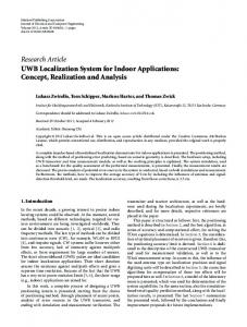
H. System Overview As illustrated in Figure 10, MaWi has two types of user: Surveyor who supplies fingerprint data, and Strayer who needs self-locating. Fingerprints from surveyor are labeled by Fingerprint Labeling Module, and then stored into Fingerprint Databases. On receiving a localization request, Revised Particle Filter draws fingerprints from databases and estimates a strayer’s location based on on-line fingerprints. Surveyor
Stray People
Wi-Fi Magnetometer Scanner
Fingerpint Labeling Module
Wi-Fi Scanner
Wi-Fi Fingerprint Database
Spot Survey Fig. 10.
Magnetometer
Similarity Zone Module (SVA)
Magn Fingerprint Database
Location
Revise Particle Filter
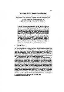
We show a real localization process on our MaWi client for five seconds in Figure 12. User stands still during the whole procedure at the lower side of the library (indicated by the particle at the 5-th second). B. Light-Weight Survey Phase
Localization
System architecture.
V.
Fig. 12. MaWi localization on a client. Sizes of red dots denote particles’ weights, and time sequence is indicated at the upper-left corner of each figure. Obviously, the weight eventually concentrates at a single particle, which happens to be the user’s ground truth location.
E VALUATION
We evaluate the performance of MaWi in this section, and we also compare it with Horus [1], a well known indoor localization system, in terms of localization accuracy. A. Experiment Setup We deploy MaWi in three test sites: an office area (Figure 1), a library (Figure 11(a)), and a shopping mall (Figure 11(b)). The dimensions of these sites and the number of
We count the time we need to build a fingerprint database that can satisfy the requirement of MaWi. We employ only one surveyor holding smart phone to walk around the deployment area, while recording the fingerprints of both Wi-Fi and magnetic field at passed location. The results in Table I show that, even for a large area of 22500 m2 , we only need no more than 1 hour to get a usable database for localization. TABLE I. Area Office Library Shopping Mall
T EST S ITES AND S URVEY T IMES Size 800 m2 3100 m2 22500 m2
Wi-Fi APs 18 ± 5 43 ± 9 27 ± 7
Time (min) 6 28 55
0.8
0.8
0.8
0.6
0.6
0.6
0.6
0.4
0.4
0.2
0.2 70
60
50
40
0.7
0.9
0.6
0.8
0.5
p
p
p
0.8
0.4
0.4
0.2
0.2
30
70
60
(a) Safety
50
40
30
0.7
0.4
0.6
0.3
0.5
55
(b) Effectiveness
50
45
40
0.2
(c) Deviation
Fig. 13. SVA under different p and θ. Best result of SVA is achieved when θ changes linearly with p. At the same time Safety and Effectiveness are both relative high.
C. Further Evaluations on SVA As SVA takes confident coefficient p as input, we need to know how to derive a proper similarity threshold θ according to it for better performance. Generally, safety decreases with p and θ (Figure 13(a)), and effectiveness increases with p and θ (Figure 13(b)). Besides safety and effectiveness, we consider another metric deviation, which is the size S of difference T area between optimal solution and SVA: |Ao Asva −Ao Asva |. We plot the relation between deviation, p, and θ in Figure 13(c). In all the three figures, we see that the best performance emerges at a strip area indicated by black dashed lines. In other words, θ should be set linearly according to p.
3
4
0.9 0.8
p
0.7 0.6 0.5 0.4 0.3
Fig. 14.
60
50
40
4 3 2 1
Localization Error (m)
2
Localization Error (m)
To analyze the relationship between SVA and MaWi’s performance, we run MaWi under different p and θ and plot the localization errors in Figure 14. Comparing it with Figure 13,
70
60
50
40
1 0.2
0.4
0.6 p
0.8
30
5 4 3 2 1
Localization error under different p and θ.
we see obvious correlation: higher localization accuracy is achieved when SVA has smaller deviation, and higher safety and effectiveness (e.g., p = 0.8, θ = −50). In our experiment, average localization error of MaWi is lower than 2.5m when deviation is below 0.3. Therefore, a good performance of SVA is crucial to the location accuracy of MaWi.
on richer ones in Figure 15(a). Even when sample number increases to 100 (5 minutes survey time) at each survey spot, Horus’s performance is still worse than MaWi. E. Localization Time Limit In Algorithm 2, we can use timeout to force the convergence of the localization process. Longer time limit gives MaWi more chances to make particle weight converge, therefore should result in higher accuracy. We set the timeouts as 5s, 8s, and 10s, respectively, and plot CDF of localization errors in Figure 15(b). MaWi’s performance improves as the time limit increasing, which confirms our expectation. F. Wi-Fi Access Point Number Generally MaWi makes use of all detectable AP, but the number of detectable APs is determined by a particular venue. In Section II-A1, we shows that a better locational discrimination can be achieve with more APs. So the question is how much the performance of MaWi is affected by the number of APs. We run MaWi in environments with 5 to 20 detectable APs and plot the localization error in Figure 15(c). Surprisingly, we find that median localization error decreases only slowly with number of APs (only decreasing 0.1 meter with 15 APs added), but the variance is much better controlled with more APs. So MaWi benefits more in stability than median error from increasing APs. VI.
R ELATED W ORK
D. Performance Comparison with Rich Database
In the last decade, indoor localization has attracted so much attention that numerous systems have been proposed. Among them, systems involving mobile devices took a large proportion [14], [1], [4], [16], [6], [10], [7], [9], [8], [11], [12], [2], [3]. This can be explained by the two main objectives of indoor localization services: 1) helping people localize and navigate themselves and 2) pushing location based services to users. Obviously, implementing localization systems on mobile devices has a potential to unify these two objectives.
To demonstrate MaWi’s advantage in localization accuracy, we compare MaWi with a proposal relying on rich databases. We choose Horus [1] as our rival; it is said to be the most accurate fingerprint-based localization system [15]. Horus utilizes multiple samples to model the distribution of Wi-Fi RSS as a Gaussian distribution for every survey spot and takes it as fingerprint. To collect such rich fingerprints for the database, we regularly choose survey spots and employ several surveyors to collect fingerprints for 10 minutes at every spot. We compare MaWi working on low quality database with Horus working
Existing proposals can be roughly put into three categories: empirical, model-based, and dead reckoning. Empirical approach (a.k.a. fingerprint-based) [1], [16], [10], [7], [9], [8], [2] collects fingerprints around the deployment area in the initial phase to assist later (empirical) localization. Modelbased approach [4], [6], [11], [3], [5], [17] employs specific devices to measure an object’s relative location to anchors or to other objects and then infers the object’s absolute location using these information; it usually entails a predeployed infrastructure. As a relative localization approach,
0.8
0.8
0.6
0.6
Mawi Horus−5 Samples Horus−10 Samples Horus−20 Samples Horus−100 Samples
0.4 0.2 0 0
5
10 15 20 Localization Error (m)
25
8
0.4 Mawi 10s Mawi 8s Mawi 5s
0.2
30
Localization Error (m)
1
CDF
CDF
1
0 0
2
4 6 8 Localization Error (m)
10
12
7 6 5 4 3 2 1 0
5
8
10
12
AP Number
15
20
(a) Comparing localization accuracy between MaWi (b) MaWi localization errors under different time- (c) MaWi localization errors under different numand Horus under fingerprint data of different quality. outs. bers of APs. Fig. 15.
Localization accuracy evaluation results
dead-reckoning [18], [19] normally needs to work along with either of the previous approaches, otherwise the cumulative errors generated by inertial sensors could render the estimated locating meaningless. As proved by [14], empirical approach can deliver high accurate localization. However the labor-intensive survey procedure (a.k.a. war-driving) has greatly hampered a wide deployment of these systems. To this end, crowd-sourcing is adopted by recent proposals [10], [9], [7], [20], [21]. Whereas crowd-sourcing distributes survey load among the crowd, it provides no quality assurance for the generated fingerprint databases. Relying only on light-weigh fingerprint databases, our MaWi achieves scalable deployment by significantly reducing the efforts required to build those databases. A new branch of indoor localization system follows the socalled device free approach [22], [23]. Since wireless signal is interfered by moving objects, this approach infers the location(s) of object(s) by analyzing the signal variance. However, as one important objective of indoor localization is to help delivering location based services, a personal mobile device would anyhow be needed. VII.
C ONCLUSIONS
In this paper, we propose MaWi, a smart phone based indoor localization system for high accurate localization and scalable deployment. Combining Wi-Fi signal and ambient magnetic field as its fingerprints, MaWi is able to work with a light-weight fingerprint database while achieving high localization accuracy, hence unifying the two objectives that have long be contradicting each other. We implement MaWi on smart phones and deploy it in multiple venues; all the experiments have strong confirmed its promising performance. R EFERENCES [1]
[2]
[3]
[4] [5]
M. Youssef and A. Agrawala, “The Horus WLAN Location Determination System,” in ACM MobiSys, 2005, pp. 205–218. [Online]. Available: http://doi.acm.org/10.1145/1067170.1067193 S. Yang, P. Dessai, M. Verma, and M. Gerla, “FreeLoc: Calibrationfree Crowdsourced Indoor Localization,” in IEEE INFOCOM, 2013, pp. 2481–2489. S. Yoon, K. Lee, and I. Rhee, “FM-based Indoor Localization via Automatic Fingerprint DB Construction and Matching,” in ACM MobiSys, 2013, pp. 207–220. K. Chintalapudi, A. Padmanabha Iyer, and V. N. Padmanabhan, “Indoor Localization Without the Pain,” in ACM MobiCom, 2010, pp. 173–184. S. Sen, J. Lee, K.-H. Kim, and P. Congdon, “Avoiding Multipath to Revive Inbuilding WiFi Localization,” in ACM MobiSys, 2013, pp. 249– 262.
[6] [7]
[8]
[9]
[10]
[11]
[12] [13]
[14]
[15]
[16]
[17]
[18]
[19]
[20]
[21]
[22]
[23]
K. Liu, X. Liu, and X. Li, “Guoguo: Enabling Fine-grained Indoor Localization via Dmartphone,” in ACM MobiSys, 2013, pp. 235–248. A. Rai, K. K. Chintalapudi, V. N. Padmanabhan, and R. Sen, “Zee: Zero-effort Crowdsourcing for Indoor Localization,” in ACM MobiCom, 2012, pp. 293–304. H. Wang, S. Sen, A. Elgohary, M. Farid, M. Youssef, and R. R. Choudhury, “No Need to War-drive: Unsupervised Indoor Localization,” in ACM MobiSys, 2012, pp. 197–210. G. Shen, Z. Chen, P. Zhang, T. Moscibroda, and Y. Zhang, “WalkieMarkie: Indoor POathway Mapping Made Easy,” in USENIX NSDI, 2013, pp. 85–98. J.-g. Park, B. Charrow, D. Curtis, J. Battat, E. Minkov, J. Hicks, S. Teller, and J. Ledlie, “Growing an Organic Indoor Location System,” in ACM MobiSys, 2010, pp. 271–284. H. Liu, Y. Gan, J. Yang, S. Sidhom, Y. Wang, Y. Chen, and F. Ye, “Push the Limit of WiFi Based Localization for Smartphones,” in ACM MobiCom, 2012, pp. 305–316. K. Subbu, B. Gozick, and R. Dantu, “Indoor Localization Through Dynamic Time Warping,” in IEEE SMC, 2011, pp. 1639 –1644. D. Fox, W. Burgard, F. Dellaert, and S. Thrun, “Monte Carlo Localization: Efficient Position Estimation for Mobile Robots,” in AAAI, 1999, pp. 343–349. P. Bahl and V. Padmanabhan, “RADAR: an In-building RF-based User Location and Tracking System,” in IEEE INFOCOM, 2000, pp. 775– 784. S. Sen, B. Radunovic, R. R. Choudhurym, and T. Minka, “You are Facing the Mona Lisa: Spot Localization Using PHY Layer Information,” in ACM MobiSys, 2012, pp. 183–196. J. Chung, M. Donahoe, C. Schmandt, I.-J. Kim, P. Razavai, and M. Wiseman, “Indoor Location Sensing Using Geo-Magnetism,” in ACM MobiSys, 2011, pp. 141–154. X. Jiang, C.-J. M. Liang, K. Chen, B. Zhang, J. Hsu, J. Liu, B. Cao, and F. Zhao, “Design and Evaluation of a Wireless Magnetic-based Proximity Detection Platform for Indoor Applications,” in ACM IPSN, 2012, pp. 221–232. P. Robertson, M. Angermann, and B. Krach, “Simultaneous Localization and Mapping for Pedestrians using only Foot-mounted Inertial Sensors,” in ACM UbiComp, 2009, pp. 93–96. F. Li, C. Zhao, G. Ding, J. Gong, C. Liu, and F. Zhao, “A Reliable and Accurate Indoor Localization Method Using Phone inertial Sensors,” in ACM UbiComp, 2012, pp. 421–430. Z. Yang, C. Wu, and Y. Liu, “Locating in Fingerprint Space: Wireless Indoor Localization with Little Human Intervention,” in ACM MobiCom, 2012, pp. 269–280. Y. Jiang, X. Pan, K. Li, Q. Lv, R. P. Dick, M. Hannigan, and L. Shang, “ARIEL: Automatic Wi-Fi Based Room Fingerprinting for Indoor Localization,” in ACM UbiComp, 2012, pp. 441–450. Y. Zhao, N. Patwari, J. M. Phillips, and S. Venkatasubramanian, “Radio Tomographic Imaging and Tracking of Stationary and Moving People via Kernel Distance,” in ACM IPSN, 2013, pp. 229–240. C. Xu, B. Firner, R. S. Moore, Y. Zhang, W. Trappe, R. Howard, F. Zhang, and N. An, “SCPL: Indoor Device-free Multi-subject Counting and Localization using Radio Signal Strength,” in ACM IPSN, 2013, pp. 79–90.