Reckoning, PDR, Indoor Positioning. I. INTRODUCTION. Wireless communication technology is rapidly expanding all around the world. Mobile devices, on other ...
Intelligent Indoor Localization System Utilizing Zigbee Wireless Networks and Inertial Sensor Integration Ahmed Tarek, College of Engineering & Technology , Arab Academy for Science & Technology, Egypt. Basem Amer, Sabratha Engineering College, Az-zawia University, Libya Prof. Aboelmagd Noureldin, Royal Military College of Canada | Queen’s University, Canada
ABSTRACT Wireless Sensor network systems are one of the supreme expansions in communications area. An example of such a network is the ZigBee wireless sensor network, which is equipped with variety of sensors and used widely in environment monitoring, healthcare, home automation, etc. Estimating location of people, assets, and portable devices can increase home automation control efficiency. PDR utilizes the accelerometers measurements to calculate the distance travelled by counting the number of steps and estimating the length of each step. The direction or heading angle is calculated from the gyroscope measurements. In this paper, we proposed an integrated PDR/Zigbee indoor positioning system to provide reliable, continuous and accurate solution. The experimental results show that the proposed Zigbee/PDR integrated solution can accurately determine the position with error distance less than two meters compared to more than five meters in case of standalone PDR. Keywords - ZigBee; RSSI; localization; Dead Reckoning, PDR, Indoor Positioning.
I.
INTRODUCTION
Wireless communication technology is rapidly expanding all around the world. Mobile devices, on other hand, equipped with state of the art technology. Mobility, portability, cheapness and the ease of use are the main features of mobile devices’ success. With the wide deployment of the
mobile wireless systems and networks, the location-based services are made possible on mobile devices, such as smart phones, tablets, and laptops [1]. Wireless Sensor network systems are one of the supreme expansions in wireless communications section. An example of such a network, is a ZigBee wireless sensor networks, which is equipped with sensors and used widely in environment monitoring, healthcare, home automation, etc. Generally, Localization is a technique for the determination of position of a moving platform with respect to a known reference, but it can also include the attitude of the platform [2]. There are numerous methods used to obtain location of a mobile object. Time of Arrival (ToA), Angle of Arrival (AoA) and Received Signal Strength (RSS) are widely used in localization applications [1]. The Angle of Arrival (AoA) is a method for computing the direction of a received radio signal from a transmitter node at a receiver node. In this method, the mobile node must be equipped with antenna array to be able to determine the angle of arrival of a received signal. The Time of Arrival (ToA) is a method based on the measurement of the delay of the radio signal between a mobile node and one or more anchor nodes. The delay is the difference between the transmission time at anchor node and reception time at mobile node, the position of the mobile node could be estimated by converting the time to distance by multiplying the time by speed of the signal.
The Received Signal Strength Indication (RSSI) method measures the signal strength from anchor nodes to the mobile node. RSSI is a well-known location method that uses a known mathematical model describing signal path loss with distance [3]. The RSSI measurement-based location systems are potential candidates to enable indoor location-aware services due to pervasively available wireless local area networks and handheld devices [1]. In this method, the mobile node position is estimated based on the measured RSSI values from at least three anchor nodes. This paper introduces an integrated indoor positioning system by integrating Pedestrian Dead Reckoning (PDR) & ZigBee modules. This integration aims to provide more accurate and reliable indoor positioning solution. The proposed method estimates the position using the Inertial Navigation Sensors (INS) which are used to achieve the PDR. The accelerometer is used to count the steps and by considering the step size as a constant, distance can be estimated. While the azimuth is calculated form the reading of the Gyroscope, after some readings correction. The remainder of this paper is organized as follows. Section 2 review previous work on indoor localization system. Section 3 explains our system model. Section 4 presents experimental results. Section 5 concludes with a brief summary and mentions future work.
II.
RELATED WORK
Inspired by GPS navigation, the hybrid navigation systems [2], [4], [5] were based on complementing GPS navigation with inertial sensors when the GPS signal was not available [2]. Integration RSS with Inertial sensors was proposed in [6] for indoor environments. This study considered as one of the first systems featuring inertial sensors and RSSI-based
indoor localization. Their proposal is based on the fusion of Wi-Fi signal strength measurements and inertial measurements provided by an accelerometer and gyroscope which are attached to the belt of the user. The accelerometer is used to count the number of steps, which is then multiplied by an average step length to obtain the travelled distance, while the angular velocity provided by the gyroscope is integrated to keep track of the rotation around the vertical axis. The study in [7] proposed a weighted Centroid Localization, which provides a simple algorithm to locate devices in wireless sensor networks. The algorithm is derived from a centroid determination which calculates the position of devices by averaging the coordinates of known reference points. To improve the calculated position in real implementations, this study uses weights to attract the estimated position to close reference points provided that coarse distances are available. In [8], they implemented a localization application utilizing wireless sensor network based on the ZigBee standard. The system automatically estimates the distance between sensor nodes by measuring the RSSI at an appropriate number of sensor nodes. Through experiments, they study clarified the validity of the data collection and position estimation techniques. The study in [9] proposed an indoor localization system with ZigBee based particle filter. The study showed this method can localize a resting target within two meters accuracy and can localize a moving target with an area levels localization. ZigBee based particle filter can be one of some options for location based services in indoor spaces. In [10], they proposed a hybrid pedestrian localization technique for indoor environments that combines an RSSI-based localization system and a PDR system
through a Kalman filter. The proposed technique has the advantage of a negligible calibration cost compared to other systems. Furthermore, numerical and real-field experiments have shown that the accuracy of the proposed system is better than other calibration-free approaches, and comparable to the accuracy obtained with more complex systems that require a timeconsuming.
III.
METHODOLOGY
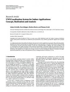
In order to provide more reliable and accurate solution, this paper utilizes the Zigbee networks to apply the integration algorithm which corrects and provide reliable solution. The flow chart of the proposed system is shown in Fig (1).
Accelerometer
PDR Gyroscope
ZigBee
PDR Position
Step Direction
RSSI
a. PDR MODULE The PDR module uses the built-in tablet’s sensors to estimate the position. The position is estimated by providing the initial position and estimating the distance walked and its direction from the initial position. The distance is calculated by counting the number of steps using the measurements of the accelerometer sensor and considering the step size as a constant. While the direction is determined from the measurements of the Gyroscope sensor, after performing a filtering technique.
i.
Step Detection Step Size
android tablet. Lastly, the correction module was devolved to correct the measurements of PDR solution using ZigBee modules.
Distance
Integration
CALCULATING NUMBER OF STEPS
Calculating the number of steps is applied by the continuous reading of the acceleration in X and Z axes every 20𝑚𝑠. In order to obtain more reliable reading the algorithm acquires 25 consecutive reading of the acceleration in X and Z axes. Then take their average. After that the algorithm calculates the RMS of the value of the average acceleration in X, Z according to the equation in Eq. (1). 𝑅𝑀𝑆 = √𝑥 2 + 𝑧 2
Corrected Position
Figure 1: Flow chart of the proposed system
In this paper, an android application was developed. The proposed method was implemented inside the android application in the form of three modules, namely, PDR (Pedestrian Dead reckoning) module, communication module and Integration module. The PDR module was used to obtain pedestrian navigation using inertial sensors. The communication module was developed in order to establish a connection between ZigBee nodes and
(1)
Consequently, the algorithm compares this RMS value with certain threshold. If the RMS value of the acceleration exceeds the value of this threshold, a counter is initialized, this counter counts the time in which the RMS value of the acceleration was exceeding the value the threshold, if this time exceeded a certain value, then it is confirmed that a step is taken and this step is detected. Based on several experiments, it was found that using the acceleration in X, Y, Z directions didn’t give a reliable result. This
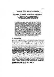
is because Y-Direction always has much more value than that of X, Z as it is indicates the acceleration due to gravity in addition to the acceleration due to the movement in its axis, as shown in Fig (2). This causes any normal changes in X, Z direction, to have no clear effect on the value of RMS, as the value of acceleration in Y direction is always much higher. So it was hard to detect steps. Thus in our proposed system, we used the acceleration in X, Z directions only and neglected the acceleration in Y direction, so that the normal changes in X, Z directions affects the RMS value, so step can be easily detected.
Y
X
b. COMMUNICATION MODULE This module is developed in order to make a connection between ZigBee nodes and tablet. The Zigbee receiver node is connected to the tablet using a USB Cable. This module establishes a serial communication between the two devices, where the ZigBee receiver receives all the signals from all the ZigBee senders and then transmits it to the tablet via the USB to serial cable. Our module receives all these measurements and stores them in a specific format [11].
c. INTEGRATION MODULE
Z Figure 2: Accelerometer axis in the android tablet
ii.
certain value then it is confirmed that it was a turn of 900. If the counter counted more time and exceeded another value, then it is confirmed that it was a turn of 1800.
DETERMINING ANGLE
THE
AZIMUTH
The azimuth angle or angle of direction is determined using the gyroscope, where the measurement of the gyroscope is read every 1.15𝑚𝑠, the algorithm compares this value with certain threshold. If the value of the gyroscope exceeds the value of the threshold, then a change in direction is confirmed. The direction of turning is known by the sign of the gyroscope reading, while the magnitude of the turn is calculated by initializing a counter as soon as a change in direction is confirmed. This counter counts the time in which the value of the gyroscope was exceeding the value the threshold, if this time exceeded a
ZIGBEE/PDR
The position determined by the PDR method has an exponential error, which leads to inaccurate positions especially in long distances. This happens as the PDR algorithm sometimes misses a step or count more steps. This error can be neglected in short distances but in long distance, it makes this solution unreliable. For that reason, we proposed the correction or an integration algorithm, which corrects the PDR solution using the Zigbee nodes. One Zigbee receiver is connected to the tablet, while other Zigbee modules senders are placed at known locations. First the integration algorithm uses the received signal strength (RSS) to get the distance between the Zigbee module sender and receiver using Eq. (2) [12, 13]: 𝑅𝑆𝑆(𝑑𝐵𝑚) = −10𝑛 log10 (𝑑) + 𝐴 (2) Where (𝑑) is the distance in meters. (𝐴) is the received signal strength in dBm at 1 meter, in our experiment the value of 𝐴 is
35 𝑑𝐵𝑚. And (n) is the propagation constant or path-loss exponent, after several testing it was taken as constant equals 3.5.
Since the Zigbee receiver is attached to the tablet and other Zigbee senders are distributed in different places, so the algorithm calculates the distance between the pedestrian holding the tablet and all other Zigbee senders. The algorithm then filters all these results to get only the signal of the nearest Zigbee sender (which is fixed in a known position). Also the correction module reads the position calculated using PDR from the previous algorithm. Thus the correction algorithm inputs are: Distance between the pedestrian holding the tablet and nearest Zigbee module sender. The position of the nearest Zigbee module sender. The position using PDR form the proposed algorithm The Correction algorithm processes all these inputs and produces more reliable solution based on several cases.
Case 2: If the ZigBee reading sates that the tablet is within 6m of the ZigBee sender, while the PDR reading sates that the tablet is more than 6m from the ZigBee sender. So we consider the PDR position is wrong and make our corrected position, which is the intersecting point of a straight line from the ZigBee sender to the PDR position and a circle with radius 3m and its origin is the ZigBee sender, as shown in Fig (4).
Figure 4: Integration Algorithm Case 2
Case 1: If the ZigBee reading sates that the tablet is within 6m of the ZigBee sender, while the PDR reading sates that the tablet is also within 6m of -the ZigBee sender. So we consider the PDR position is correct and leave it without changing as shown in Fig (3).
Case 3: If the ZigBee reading sates that the tablet is between 6m and 12m from the ZigBee sender, while the PDR reading sates that the tablet is also between 6m and 12m from the ZigBee sender. So we consider the PDR position is correct and leave it without changing as shown in Fig (5).
Figure 5: Integration Algorithm Case 3
Figure 3: Integration Algorithm Case 1
Case 4: If the ZigBee reading sates that the tablet is between 6m and 12m from the ZigBee sender, while the PDR reading sates that the tablet is less than 6m from
the ZigBee sender. So we consider the PDR position is wrong and make our corrected position the intersecting point of a straight line from the ZigBee sender to the PDR position and a circle with radius 9m and its origin is the ZigBee sender as shown in Fig (6).
correction is unreliable and we use only the PDR position as shown in Fig (8).
Figure 8: Integration Algorithm Case 6
IV. Figure 6: Integration Algorithm Case 4
Case 5: If the ZigBee reading sates that the tablet is between 6m and 12m from the ZigBee sender, while the PDR reading sates that the tablet is more than 12m from the ZigBee sender. So we consider the PDR position is wrong and make our corrected position the intersecting point of a straight line from the ZigBee sender to the PDR position and a circle with radius 9m and its origin is the ZigBee sender as shown in Fig (7).
EXPERIMENTAL EVALUATION
The experiments were conducted in the 5th floor, at the Electrical Engineering building, at Royal Military Collage of Canada, Kingston, Ontario, Canada. The layout of the floor is shown in Fig (9).
Figure 9: The path the pedestrian during the experiment and the position of the Zigbee senders
Figure 7: Integration Algorithm Case 5
Case 6: If the ZigBee reading sates that the tablet is more than 12m from the ZigBee sender, while the PDR sates anything. So we consider the Zigbee
The experiment was implemented using an Android tablet (Samsung) [13], connected with ZigBee receiver CC2530 modules operating at 2.4 GHz via a USB cable [14]. The tablet and the Zigbee receiver are being carried by a pedestrian mounted on the chest. The pedestrian was walking normally during the experiments to collect data at different locations. The Zigbee network consists of ten Zigbee senders were placed at known locations.
The true trajectory, the pedestrian during the experiment and the layout of the Zigbee network are shown in Fig (9). The layout of the android application is shown in Fig (10).
Figure 10: The layout of the android application
obtained from the PDR algorithm only was exponential. This caused by the PDR algorithm sometimes misses a step or count more steps. While the error obtained from the integration solution was also as expected, as it was significantly much less than the error from the PDR only. The error in PDR only and the error in PDR/Zigbee were plotted for each step in Fig (11). Also the position of each step made by the pedestrian during our experiment was calculated two times. The first with the position obtained from PDR only. The second with the position obtained from the PDR/ZigBee. Thus, by adding all these steps, two passes were formed, in addition to the true pass. These three passes were plotted on the map as shown in Fig (12).
After conducting the experiment, the RMS of the error in each step was calculated two times. The first with the position obtained from PDR module only. The second with the position obtained from integration of PDR and ZigBee modules. As expected the error
Figure 11: Error in PDR and PDR/ZigBee integration
True Path
PDR only
PDR & Correction Algorithm
Figure 12: The three passes on the map (True path, PDR only, PDR & Correction Algorithm)
Thus, it was found that the correction algorithm decreased the overall RMS error of the system from 4.27m in case of PDR only to 1.86m in case of PDR and correction algorithm. Thus we have found a very simple, cost effective solution, to increase the efficiency of indoor positing systems.
V.
CONCLUCSION WORK
AND
FUTURE
In this work, we proposed an Integrated Indoor positioning system employing two modules, namely, Pedestrian Dead reckoning module (PDR) & ZigBee wireless module. PDR module utilizes device’s builtin inertial sensors, accelerometer and gyroscope, which calculated by estimating the walked distance and its direction. Unfortunately, the position determined by the PDR only method has an exponential error, which leads to in accurate especially in long distances. For that, we proposed an integration PDR/ZigBee system. The proposed positioning system was
implemented by using ZigBee CC2530 modules. The experimental results show that the proposed integration algorithm PDR and Zigbee can accurately determine the position with error distance less than two meters compared to more than five meters in case of PDR only. Our Future work will include adding Bluetooth module to transmit our corrected position from the tablet to the certain control room in this building to be able to monitor the position of each person. Our prospective work also will include Automatic decision making software’s as fuzzy or neural networks, which may improve the position and get better result.
REFERENCES [1]
[2]
Amer, B., & Noureldin, A. (2014). A Survey of Recent Indoor Positioning Systems using Wireless Networks. IJECCE, 5(5), 1197–1204. A. Noureldin, T. B. Karamat, and J. Georgy, Fundamentals of Inertial
Navigation, Satellite-based Positioning and their Integration. Berlin, Heidelberg: Springer Berlin, 2013. [3] P. Lin and B. A. Sc, “Pure RSSI Based Low-Cost Self- localization System for ZigBee WSN by In the,” 2011. [4] T. B. Karamat and M. M. Atia, “Performance Analysis of CodePhase-Based Relative GPS Positioning and Its Integration With Land Vehicle ’ s Motion Sensors,” IEEE Sens. J., vol. 14, no. 9, pp. 3084–3100, 2014. [5] T. Bin Karamat, “Improved Land Vehicle Navigation and GPS Integer Ambiguity Resolution using Enhanced Reduced-IMU / GPS Integration By,” Ph.D. dissertation, Dept. Elect. Eng., Queen’s Univ., Kingston, ON, 2014. [6] R. C. Luo and O. Chen, “Wireless and pyroelectric sensory fusion system for indoor human/robot localization and monitoring,” IEEE/ASME Trans. Mechatronics, vol. 18, no. 3, pp. 845– 853, 2013. [7] Blumenthal, J., Grossmann, R., Golatowski, F., & Timmermann, D. (2007). Weighted Centroid Localization in {ZigBee}-based Sensor Networks. In IEEE International Symposium on Intelligent Signal Processing (pp. 1–6). [8] Sugano, M. (2006). Indoor Localization System using RSSI Measurement of Wireless Sensor Network Based on Zigbee Standard. From Proceeding 538 Wireless Sensor Networks, 7, 54–69. [9] F. Evennou and F. Marx, “Advanced integration of WiFi and inertial navigation systems for indoor mobile positioning”, Eurasip Journal on Applied Signal Processing, Vol 2006, pp. 1–11, January 2006. [10] P. Tarrio, J. A. Besada, and J. R. Casar, “Fusion of RSS and inertial measurements for calibration-free indoor pedestrian tracking,” in
[11]
[12]
[13] [14]
Information Fusion (FUSION), 2013 16th International Conference on, 2013, pp. 1458–1464. Basem Amer, Atia, M., Hefnawi, M., & Noureldin, A. (2015). An Adaptive Positioning System for Smartphones in Zigbee Networks Using Channel Decomposition and Particle Swarm Optimization. In The institute of Navigation (ION) International Technical Meetings (ITM 2015). Dana Point, CA, USA: The Institute of Navigation (ION). Guvenc, I. (2003). Enhancements to RSS Based Indoor Tracking Systems Using Kalman Filters. IEEE Pervasive Computing, (505), 91–102. Android Developers. (2015, Aug 10) [Online]. Available: http://developer.android.com. Texas Instruments, CC253x Systemon-Chip Solution for 2.4-GHz IEEE 802.15.4 and ZigBee® Applications, Texas Instruments, 2013.