Jun 30, 2006 - (4,5), Slicer (6), Julius (7) and CISST (8). The software requirements for these systems are becoming increasingly complex as a result of recent.
The SIGN: A dynamic and extensible software framework for Image-Guided Therapy Release 1.00
Eigil Samset12, Arne Hans1, Jochen von Spiczak13, Simon DiMaio1, Randy Ellis1, Nobuhiko Hata1 and Ferenc Jolesz1
June 30, 2006 1
Brigham and Women’s Hospital, Boston, MA, USA 2 University of Oslo, Norway 3 University of Karlsruhe, Germany
Abstract The software requirements for computer-aided navigation tools in image-guided therapy are becoming increasingly complex as a result of new possibilities in imaging and tracking hardware, novel application areas and regulatory restrictions. A new software framework has been developed to meet the needs of emerging image-guided procedures and therapies that require multi-modal imaging and tracking. This framework accommodates dynamic data-structures, dynamic input and output interfaces for interventional devices, and dynamic visualization of data. Arbitrary, yet meaningful, connections can be established between these entities in order to implement customized applications that target specific clinical procedures. A series of demonstration applications have been developed in order to emphasize different aspects of the framework, and are presented here.
Contents 1
Introduction
2
1.1
New possibilities in imaging hardware
2
1.2
New possibilities in tracker hardware and other devices
3
1.3
Regulatory requirements
3
1.4
Context: AMIGO – Advanced Multi-modality Image-Guided Operation suite
4
2
Methods
4
2.1
Imager Interfacing
4
2.2
Tracker Interfacing
5
2.3
Hybrid Interfacing
5
2.4
Application framework
6
2
2.5
Application silos
7
2.6
Software components used
7
3
Results
8
3.1
Generic navigation application
8
3.2
Endoscopic navigation
9
3.3
Cardiac navigation
9
3.4
Out-of-plane biopsy guidance
10
3.5
Multi-modal Player
10
4
Conclusions
11
5
Acknowledgements
11
6
References
11
1
Introduction
Computers have come to play an increasingly important role in Image-Guided Therapy. The field has been able to make rapid advances over the last decade thanks to the push towards faster and more affordable computational and visualization power in commodity desktop computers. Applications such as neuro-navigation (1), CT-guided orthopedic interventions (2), virtual endoscopy (3) and many others are good examples of clinical applications where computer-aided navigation technology plays a central role. There are a number of commercial systems available in the marketplace, and recently several open systems have been developed in the academic community. Examples of open systems include IGSTK (4,5), Slicer (6), Julius (7) and CISST (8). The software requirements for these systems are becoming increasingly complex as a result of recent advances in imaging- and tracking hardware, novel application ideas and regulatory restrictions. Some of these requirements will be discussed in this paper.
1.1
New possibilities in imaging hardware
Image-guided therapy can be performed with the aid of a wide range of imaging modalities. There is currently a trend towards the use of multiple imaging modalities during the course of a procedure. Traditionally, MRI and CT have been used to provide pre-operative images that can act as roadmaps for intra-operative navigation. Amongst newer additions to the tomographic family of image-modalities that are becoming commonplace are PET and 3D C-arms. More recently these imaging modalities have been
3
utilized to an increasing extent for intra-operative imaging. Ultrasound is also increasingly used is and intra-operative tool, and 3D ultrasound has the potential to further increase the usefulness of ultrasonography. Both interventional MRI and interventional CT have grown to become large independent fields of research. The software challenges in using intra-operative imaging, from one or multiple imaging instruments include proper functionality, portability, abstraction and speed. In this paper we will present a framework that has a feature set that satisfies these basic requirements.
1.2
New possibilities in tracker hardware and other devices
In the early days of surgical navigation systems, the most common instrument tracking modality was optical tracking (preceded by mechanical tracking). Although several new tracking modalities have since become available, optical tracking remains the most used tracking modality due to its high tracking accuracy. Nevertheless, the applicability of optical tracking is limited by its inherent problem that a clear line of sight is required. Electromagnetic tracking has emerged as a promising tracking modality for intracorporal tracking. It can be used to track needles, catheters, endoscopes and other tools inside the patient’s body. A review of tracking devices can be found in reference (9). Modern tracking systems have an extensive feature set and can, in addition to tracking multiple tools, also provide the application programmer with information about tool identities and definitions, confidence and calibration states. Some applications have been found to benefit from using several tracking systems simultaneously, either of the same type or based on different tracking modalities. This is typically done to increase the field of view and for multi-resolution tracking. Tracking techniques are also being used for more than just tracking surgical tools, but also to track patient anatomy (to compensate for movement, or measure movement in dynamic procedures) or the surgeon (in situations were techniques such as Augmented Reality are being exploited). Software challenges similar to those found in the interaction with imaging hardware are present in the implementation of tracking systems, i.e., proper functionality, portability, abstraction and speed, as well as networking capabilities, tracker-interoperability and advanced filtering. As will be described in this paper, the shared requirement between imaging and tracking can be exploited in order to create a common framework for interfacing, processing and communication of intra-operative abstract events.
1.3
Regulatory requirements
The Medical Device Directive in Europe and the Food and Drug Administration (FDA) Medical Device Amendments and Safe Medical Devices Act in USA were originally designed to provide patient safety with respect to tangible medical devices. With therapy delivery systems becoming more reliant on computer systems, and intra-operative decision-making being partly based on information presented on a computer screen, these regulatory documents have been updated to include stricter requirements for to the design, testing and performance of computer programs. Obtaining FDA or CE clearance for commercial software to be put into the market place is a labor intensive and expensive process. In addition, academic software that can be used to aid patient treatment
4
as research tools under IRB approval, has come under increased scrutiny and is now subject to stricter regulations. This is a positive step and gives academic software development processes new challenges. The key elements that will be discussed in this paper, with regard to the design of safe software for clinical use are: design processes, testing and code separation.
1.4
Context: AMIGO – Advanced Multi-modality Image-Guided Operation suite
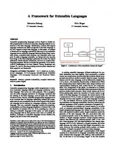
The present study was performed with the purpose of providing a safe, dynamic and extensible software framework for image-guided therapy in a novel operation facility called AMIGO. The AMIGO facility is depicted in Figure 1 and constitutes a suite of three operation rooms. In the middle is a fully equipped operating room (OR) with state of the art instrumentation for a broad range of surgical and interventional procedures. Adjacent to this room are two operation rooms containing a 3T MRI scanner and a PET/CT scanner, respectively. A patient transportation mechanism, with a thin ultra-stiff X-Ray- and MRI-compatible transfer board and floor rails allows seamless relocation of the patient between the different imaging and operating stations. The Figure 1 The AMIGO facility. Three operation rooms suite is designed to be multi-purpose, and it is are connected by a patient transport mechanism. The envisioned that multiple procedures can be suite features both and a 3T MRI scanner and a performed within the facility at the same time, PET/CT. with different combinations of the three operation rooms. The challenge for navigation software development in this context is to accommodate for all possible combinations of tracking modalities and configurations, imaging modalities and innovative therapy delivery systems—both current and future. The AMIGO facility will be the first large-scale deployment of the presented framework. Subcomponents of AMIGO will be used in testing stages.
2 2.1
Methods Imager Interfacing
A software interface for imaging equipment such as MRI scanners, US scanners or video-endoscopic cameras was implemented as a separate library called GIHI (General Imager Hardware Interface). This was written using the C programming language, for maximum portability, and has no dependencies (unlike the other libraries and applications that will be described). It was a requirement in the design of GIHI that even legacy computer platforms that are sometimes used in older imaging equipment could be
5
supported. GIHI provides network communication utilities (through TCP/IP) and abstraction of three services. These services are: • Image service. Provides real-time images and associated header information in a packet. • Tracking service. Provides abstraction of tracker sources that may be embedded inside the imaging equipment • Command service. Provides the means to change parameters and control the scanner such as to define scan location and orientation. The interface developer will write a plug-in (dynamically loaded library) for each of these services, for a particular scanner. GIHI currently includes plug-ins for: GE Signa SP (0.5T MRI scanner with vertical opening), GE Excite (current platform for MRI scanners from General Electric Medical Systems), video4linux (to get video stream from e.g. Ultrasound scanners) and a simulator.
2.2
Tracker Interfacing
Tracking systems are interfaced using OpenTracker—a comprehensive C++ library that provides abstraction for the tracking hardware, as well as facilities for distributed systems, static and dynamic coordinate transforms, filters and application integration. OpenTracker was originally designed in the domain of Virtual Reality (VR) and Augmented Reality (AR); therefore, it supports a wide variety of trackers typically used for VR and AR applications. New modules were added to the OpenTracker in order to implement data sources and sinks for interfacing with the medical trackers: • Flashpoint® (Image Guided Technologies Inc., Boulder CO): optical tracker consisting of three 1D cameras and LEDs mounted on surgical tools. • NDI Aurora® (Northern Digital Inc., Ontario Canada): electromagnetic tracker with miniature sensors. • NDI Polaris ® (Northern Digital Inc., Ontario Canada): optical tracker using either wireless reflective spheres or active LEDs and two 2D cameras. • EndoScout®, (Robin Medical, Baltimore MD): electromagnetic tracking for the MRI environment. • Phantom® (Sensable Technologies, Woburn MA): a haptic device used as a prototyping interface for surgical robots and simulators.
2.3
Hybrid Interfacing
While supporting a large variety of tracking systems and allowing for easy XML based configuration of changing hardware setups, a significant shortcoming of the version 1.1 of the OpenTracker library was its fixed set of event data fields strictly limiting its use to tracking related applications. By extending the OpenTracker library, a general device interface library was developed for the integration of not only tracking systems, but also imaging systems, peripheral devices, device controllers, data loggers, and other systems. It uses an underlying data structure that is dynamic so that events are no longer limited to a fixed set of data fields; therefore, new devices and applications can easily be integrated. Each event consists of several data fields or attributes that can be created dynamically. Each node that creates or transforms an event can add new attributes or access them by name.
6
A large variety of different data types for event attributes are supported and this set of types can be further extended. The architecture puts no constraints on the data types to be used within the library. A comprehensive description of this refactoring of OpenTracker is given in (11). Making use of the additional functionality, interfaces for devices that supply more than tracking information or devices that only supply other, non tracking related information were designed. These bidirectional device interfaces were implemented as separate modules, which can be loaded into the library. Each module provides a data source and a data sink to receive information provided by the device or send control information to the hardware, respectively. The following modules were developed: • MedScan, a module that interfaces with the GIHI library in order to encode all services as events. A MedScanSource can provide image data and image pose information (encoded as tracking data) as well as other parameters in a composite event. A MedScanSink can carry position and orientation prescriptions (encoded as tracking data) as well as other control parameters in one event. • Terason, an ultrasound probe by Terason Ultrasound (Teratech Corporation, Burlington MA), provides events containing ultrasound images and associated information. • ECG, a module that samples a patient’s ECG signal using a National Instruments USB data acquisition system and analyzes the signal to detect the heart rate. An event is dispatched for every QRS complex that is detected, and includes information about the heart rate. • Raw Data Server, a module for capturing k-space data on a GE MRI running the Excite platform.
2.4
Application framework
An application framework was implemented, using C++, in order to provide a powerful set of tools for the development of novel clinical applications that require real-time interaction with multiple systems and task-supportive visualization interfaces. The framework was designed to be highly interoperable with the 3D Slicer, an established toolkit for image processing and analysis (6). Its close relationship with the 3D Slicer is reflected in the name of the application framework—The Slicer Image-Guided Navigator (The SIGN). Currently the inter-operability is limited to the exchange of scene-description files. As Slicer is currently undergoing a redesign, closer links will be established.
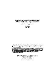
Figure 2 A block diagram describing the dynamic data structure and connections in The SIGN. Data can be dynamically configured using Mrml. Tracking and device interaction can be dynamically configured using OpenTracker. Views in the user interface can be dynamically configured in The SIGN user interface classes and configuration files. Connections between data, devices and views can be established
Slicer uses the Medical Reality Modeling Language (MRML) as its data model. This data model is also used by The SIGN and provides a simple way to serialize the data elements, such as image volumes, surface models, and geometric transformations, into an XML file. MRML also encapsulates some information about viewer configuration.
7
A dynamic execution model was designed to unify three different dynamic concepts (Figure 2), including: • a dynamic data model, through the use of MRML, • dynamic tracker and device interface ports through the use of OpenTracker and GIHI, and • dynamic viewer configuration through the implementation of application-specific graphical user interfaces and an XML-based configuration file. The framework allows for connection between these concepts through the use of node name matching. An object or image volume in the MRML tree can be connected to a tracker in the tracker tree. This connection is established if a name match is found between the two trees. Such a connection allows a tracker input to move an object around in the scene. A tracker input can also be connected to a view. This could typically mean that the slice displayed in a 2D viewer is determined based on the position of the tracker. Such connections are implemented through a node called a SignSink. Non-tracker event streams, such as originating from an image source, can also be connected to a viewer in order to update the display of images. Lastly, data in the MRML tree will be presented in a viewer based on a configuration file that defines the initial display setup. This design allows for integration of multiple trackers and image devices in a single setup, unlike the other open navigation systems mentioned in the introduction. Such scalability and flexibility becomes increasingly relevant as several procedures utilize multi-modal imaging and multiple trackers are used to increase the field of view (e.g. combined electromagnetic tracking for intra-corporal tracking and optical tracking for extra-corporal tracking). Complex setups like this are foreseen to be typical in the AMIGO context.
2.5
Application silos
To meet regulatory requirements, in terms of documentation, testing and software safety, the design structure implies that specific software applications are to be implemented as separate silos. This means that a software application implemented using The SIGN will typically not be multi-purpose, but strictly target a specific clinical need. The application will still make use of the application framework, but the application silo draws clear borders that facilitate testing in finite time. An application will at a minimum consist of the following elements, in addition to The Sign application framework: • A GUI class describing the screen layouts. • A Process class describing the overall workflow, or steps in the clinical procedure. This will typically have a one-to-one relationship with a storyboard that describes the workflow. This class includes rules taking the application from one screen to another. • A file implementing the main() function that bootstraps the framework for a specific application. In addition to this, any number of application-specific classes can be added. Classes of generic value will be considered as candidates for incorporation in the application framework.
2.6
Software components used
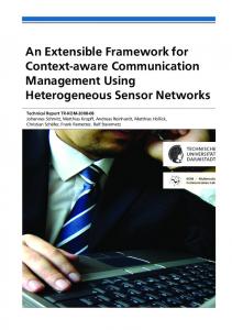
The Sign makes extensive use of open source software components. It is currently relying on (Figure 3): • VTK (cvs head) The Visualization Toolkit by Kitware, a pipeline based 3D graphics library, www.vtk.org
8
• • • • • • • •
KWWidgets (cvs head) by Kitware, an object oriented GUI toolkit, wrapping the functionality of Tk in c++. It has tight links to VTK, while independent. www.kwwidgets.org ITK www.itk.org vtkITK OpenTracker v1.3 www.studierstube.org/opentracker SPLOT, our set of extention modules to OpenTracker GIHI, General Imager Hardware Interface https://ariser.uio.no/website/doc/gihi_doc/html/ Xerces, a xml parsing library http://xml.apache.org/xerces-c/ ACE, a networking library http://www.cs.wustl.edu/~schmidt/ACE.html
Figure 3 The Sign’s library dependencies
3
Results
The results will be presented as a summary of example applications implemented using The Sign application framework. This demonstrates how the present framework can be used in a variety of applications. The Sign is planned for release to the open source community on October 19th (details will be available on http://www.ncigt.org/sign). This release includes the framework and two example applications (including the Generic navigation application). The components OpenTracker and GIHI, which are parts of this effort, are currently available for download.
3.1
Generic navigation application
To demonstrate the basic functionality of The Sign a generic application was implemented. This application can view any MRML tree in a 3D viewer. Three 2D viewers can show cross sections of a volume or real-time images from any source. The application supports physical-space-to-image-space registration with the use of fiducials that are defined in image-space using a 2D viewer and in physicalspace using a tracker. By using The Slicer as a surgical planning tool for image registration and segmentation, the generic navigation application in The Sign can use this data and provide powerful navigation support for multiple configurations. Most applications, however, require further customization.
9
3.2
Endoscopic navigation
This application targets intra-cranial minimal invasive surgery using endoscopes to operate the brain from the “inside-out” (10). A flexible endoscope is instrumented with electromagnetic tracking micro sensors. The configuration of trackers including dynamic-reference sensors and calibration matrices were defined in an OpenTracker graph using the XML file format. The screen layout includes screen panels for showing the virtual endoscopic view, an overview image and the real endoscopic image (Figure 4). The endoscopic image from the camera will also be available on a separate monitor. Figure 4 Endoscopic navigation example screen. The upper left panel shows the segmented CT data of the skull, ventricles and tumor. The endoscope is depicted as red. The upper right panel shows the endoscopic view. The lower left panel shows the fiducial markers and the middle panel a MRI cross-section. The real endoscopic image will be displayed in the lower right.
3.3
Cardiac navigation
An application to aid cardiac interventions was developed, with the particular focus of supporting interventions under MRI guidance. A specific feature of the application is to enable the display of cineloops in 3D or 2D viewers triggered by real-time ECG. In addition, the application allows for display of catheters in 3D or projected in 2D views using a mathematical model of the catheter and two 6DOF sensors embedded in the catheter. The ECG acquisition system was implemented by connecting the patient’s intra-operative ECG to a PC through a National Instruments USB data acquisition unit. The ECG signal analysis included real time detection of the QRS complex as well as the heart rate (figure 1). An event was dispatched to the visualization system immediately following Figure 5 Cardiac navigation application. The MRI acquired images are displayed using volume rendering and three reformatted orthogonal views. A realtime image can replace one of the 2D views. A simulated catheter is shown in the 3D view and projected into the 2D views.
10
QRS detection including information about the current heart rate. At the same time as displaying pre-acquired volume cine-loops, real-time images can be displayed in the 3D view and annotated with tracked devices such as catheters. The real-time 2D images are spatially and temporarily registered with the 3D roadmap. The navigation screen from the visualization application is shown in Figure 5. The combined display allowed for coarse orientation (3D view), detailed navigation (high-res 2D roadmaps) and verification (real-time 2D scan), and can potentially simplify navigation to complex anatomical structures such as pulmonary veins or contrast enhancing myocardial scars.
3.4
Out-of-plane biopsy guidance
Most image-guided biopsies and placement of probes are guided with in-plane techniques such as ultrasound. MRI-is typically acquired in anatomic orthogonal planes, although any single or double angle oblique plane is possible. CT has only limited capability of tilting away from the standard axial acquisitions. Although MRI or CT images can be reformatted, this requires thin and contiguous slices. The out-of-plane biopsy guidance application allows display of images in well-defined nonreformatted planes (such as axial) while giving a good understanding of the needle trajectory to radiologists trained in cross-sectional imaging. This is accomplished by displaying four userdefined planes, annotated with the point of intersection of the needle trajectory with this plane (Figure 6).
3.5
Figure 6 Screen short of out-of-plane guidance application. The needle trajectory is annotated as the point of intersection on four user selected axial planes.
Multi-modal Player
In this application, any information encoded in the OpenTracker event format can be replayed in realtime. Intra-operative events can be saved and displayed at a later point in time for monitoring, analysis, review, or documentation. Using a FileSink, information gathered during a procedure can be saved. The so-called EventPlayerSource retrieves information from the saved file and pushes out events in the correct order and with the correct delay between successive events. This application demonstrated the usefulness of the abstraction and general applicability of the OpenTracker library and constitutes a general tool for reviewing interactions.
11
4
Conclusions
The SIGN address new challenges in Image-Guided Therapy (IGT) related to multi-modal imaging and tracking. By utilizing existing open source tools (VTK, ITK, KWWidgets...), contributing to existing open source projects (OpenTracker) and augmenting existing projects (SPLOT), a new software framework for IGT was developed. The software has several advanced features that were demonstrated in several applications with high clinical relevance. The dynamic configurability of The SIGN allows for rapid development of new applications. The complexity of future operation facilities such as AMIGO, was address in SIGN through the ability to dynamically allow multi-modal tracking and imaging configurations.
5
Acknowledgements
This publication was made possible by grants from the Research Council of Norway, CIMIT and NIH (Grant number RR019703). Its contents are solely the responsibility of the authors and do not necessarily represent the official views of the NIH.
6
References 1. U. Spetzger, G. Laborde, JM Gilsbach, Frameless neuronavigation in modern neurosugery, Minimally Invasive Neurosurgery, 4(38), pg. 163-166, 1995 2. M. Arand, E. Hartwig, L. Kinzl, F. Gebhard, Spinal navigation in cervical fractures—a preliminary study on Judet-osteosynthesis of the axis, Computer Aided Surgery, 3(6), pg. 170175, 2001 3. B. Braticevici, M. Onu, F. Bengus, Virtual cystoscopy – a surgical planning and guidance tool, Arch Ital Urol Androl, 1(78) pg. 23-24, 2006 4. http://hdl.handle.net/1926/31 5. http://www.igstk.org 6. http://www.slicer.org 7. http://www.julius.caesar.de 8. http://www.cisst.org/cisst/ 9. D.A. Simon, Intra-operative Position Sensing and Tracking Devices, Proceeding of the First Joint CVRMed / MRCAS Conference, 62-64, 1997. 10. J. Wada, S. DiMaio, S. Pujol, L. Goumnerova, F. Jolesz, Development of a Navigation System for Neurofiberscopic Surgery, Symposium of the International Brain Mapping and Intraoperative Surgical Planning Society, 2005.
12
11. J. von Spiczak, S. DiMaio, G. Reitmayr, D. Schmalstieg, CR Burghart, E. Samset, Multi-Modal Event Streams for Virtual Reality, Multimedia Computing and Networking Conference, San Jose, CA, 2007 (accepted)