A Dynamic Momentum Compaction Factor Lattice in the FERMILAB. DEBUNCHER Ring. D.N. Olivieri, M. Church, and J. Morgan. Fermi National Accelerator ...
A Dynamic Momentum Compaction Factor Lattice in the FERMILAB DEBUNCHER Ring D.N. Olivieri, M. Church, and J. Morgan Fermi National Accelerator Laboratory � P.O. Box 500 Batavia, IL 60510 I. Introduction The primary purpose of the Fermilab Debuncher ring is twofold; to accept approximately �A/pulse of 8.9 GeV antiprotons (p) downstream from the production target and to subseto quently reduce the momentum spread, from p=p � � : , and transverse emittance, from � � � mm-mrad to � � mm-mrad, for improved transfer and stacking performance in the Antiproton Accumulator ring. To accomplish this objective, rf- cavities are used to rotate and adiabatically debunch the beam on the time scale of � msec, after which stochastic cooling systems, both transverse and longitudinal, are used to reduce the transverse emittance and longitudinal momentum spread throughout the remainder of the � : sec p production cycle. In the initial and present design of the Debuncher ring, the momentum compaction factor (�), or equivalently the slip factor, � � = 2 , was chose to have a value which is a compromise between the two competing functions of the ring - that of accepting and debunching a large number of ps/pulse and subsequently employing stochastic cooling feedback systems to precool before injection into the Accumulator. The goal of this experiment is to reconcile this compromise by changing � between two desired values during each p production cycle.
7
� 2%
� 20
5
4%
40
24
=
the straight sections for the purpose of locating rf- cavities and stochastic cooling devices. As a result of the dispersion killer chosen, each regular FODO cell has a phase advance of �= . The ring operates on the positive side of transition with large dispersion in the arcs, thus limiting the momentum acceptance upon injection. The dispersion function in the arcs reaches a maximum value of 2.4 m and the maximum transverse beta functions are approximately 14 m with tunes typically operated at 9.79 horizontal, and 9.77 vertical.
3
�
1
�
�
II. On Magnetic Optics Modifications to the FNAL Debuncher The momentum compaction factor is the difference in the perimeter between the orbits of particles with differing momentum from that of the ideal design particle. Thus,
�C = � �p C
�=
p 1 I D(s) ds C �(s)
These relations suggest the following simple fact, that in order to modify � of an existing lattice, it is sufficient to change the dispersion function. The Debuncher ring has a circumference of 505 m and is composed of a sixfold symmetric seperated function optical lattice[1]. The basic arrangement of the ring consists of three long dispersion free straight sections together with arc sections consisting of 57 regular FODO achromats in total. Transition from the arcs to the straights is accomplished with a missing magnet scheme to produce a strictly zero horizontal dispersion in � Operated by the Universities Research Association, Inc. for the U. S. Department of Energy
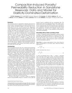
Figure. 1. Comparison of the dispersion function for different design cases to that of the nominal case with �(nominal) To accomplish the task of uniformally changing the dispersion function in the arc sections, while maintaining a large number of practical constraints, interleaved localized dispersion waves were created by perturbing the strengths of judiciously chosen quadrupole pairs seperated by � in nominal betatron phase advance. Amongst some of the constraints were the requirements that: (i) perturbations to any quadrupole should not exceed � � Amps due to the present power supply limitations, (ii) the tunes shifts in either plane may not exceed �x;y � �: to avoid resonance crossing, (iii)the dispersion function remain strictly zero in the straight sections due to the location of stochastic cooling devices and rf- cavities, and (iv) the functions not exceed of their nominal values (except at the locations of the stochastic cooling pickup and kickers, for which one desires a large amplitude for increasing the sensitivity factor). Together with these constraints is the very important constraint that the phase difference between the pickup and kicker either remain the same or move closer to optimal for the correct phasing of the stochastic cooling system.
20
�
10%
005
A comparison of the dispersion functions in one sector for the nominal lattice and that for the lattice with a value of � 1.5 times larger is given in Figure 1. The lattice design for both large and small � maintain six- fold symmetry. Furthermore, the lattice designs for each case are symmetric in the required �I of each quadrupole from the nominal design lattice, i.e. it is merely a change of sign of each �I in the change from : � ! : �.
05
15
A. Sensitivity to the Resonance Lines A change in dispersion function in the arcs is accompanied with relatively large tune shifts, which must be removed through adjustments of the quadrupole fields in the zero dispersion straight sections. Thus it is required to understand the features of the resonance structure in the vicinity of the operating point. In particular, if the tunes are not properly corrected while differentially changing the lattice at each step with nonlinear ramps, relatively large tune excursions can occur during the ramping process for which beam loss may result due to resonance crossing. An experimental investigation was undertaken to map out the amplitude and widths of the resonances throughout a relatively large area of tune space ( �: units in both planes) sufficient for the purposes of this project. The major resonance lines together with their relative width and strength are given in Table 1. Avoiding these resonances during the ramping process puts heavy restrictions on allowable tune excursions.
Estimates for an increased transverse stochastic cooling rate, due to the larger �, can be obtained through an integration of the first moment integral of the Fokker Plank equation which describes the time evolution of the transverse density function.
X d� 0 =