FIC as developed by Truong et al. ..... 0.55 dB and 0.07 dB for Lena, Peppers and Baboun images ... The CR decreases slightly when SFâ¤0.2 (0.99 for Lena,.
A fast fractal image encoding based on Haar wavelet transform Sofia Douda Département de Mathématiques et Informatique & ENIC, Faculté des Sciences et Techniques, Université Hassan 1er, Settat, Morocco. .
Abdallah Bagri ENIC, Faculté des Sciences et Techniques, Université Hassan 1er, Settat, Morocco.
Abstract—In order to improve the fractal image encoding, we propose a fast method based on the Haar wavelet transform. This proposed method speed up the fractal image encoding by reducing the size of the domain pool. This reduction uses the Haar wavelet coefficients. The experimental results on the test images show that the proposed method reaches a high speedup factor without decreasing the image quality. Keywords- Fractal image compression, PIFS, Haar wavelet transform, SSIM index.
I.
INTRODUCTION
Fractal image compression (FIC) is one of the recent methods of image compression firstly presented by Barnsley and Jacquin [1-5]. This method is characterized by its high compression ratio which is achieved with an acceptable image quality [6], a fast decoding and a multi-resolution property. It is based on the theory of Iterated Function System (IFS) and on the collage theorem. Jacquin [3-5] developed the first algorithm of FIC by Local or Partitioned Iterated Function Systems (PIFS) which makes use of local self-similarity propriety in real images. In FIC, the image is represented through a contractive transformation defined by PIFS for which the decoded image is approximately its fixed point and close to an input image. In Jacquin’s algorithm, an input image is partitioned into non-overlapping sub-blocks Ri called range blocks, the union of which covers the whole image. Each range block Ri is put in corresponding transformation with another part of a different scale, called domain block, looked for in the image. The domain blocks can be obtained by sliding a window of the same size around the input image to construct the domain pool. The classical encoding method, i.e. full search, is time consuming because for every range block the corresponding block is looked for among all the domain blocks. Several methods are proposed to reduce the time encoding. The most common approach is the classification scheme [6-10]. In this scheme, the domain and the range blocks are grouped in a number of classes according to their common characteristics. For each range block, comparison is made only for the domain blocks falling into its class. Fisher’s classification method [6] constructed 72 classes for image blocks according to the variance and intensity. In Wang et al. [10], four types of range
Abdelhakim El Imrani LCS, Faculté des Sciences, Université Mohammed V, Rabat, Morocco.
blocks were defined based on the edge of the image. Jacobs et al. uses skipping adjacent domain blocks [11] and Monro and Dudbridge localizes the domain pool relative to a given range block based on the assumption that domain blocks close to this range block are well suited to match the given range block [12]. Methods based on reduction of the domain pool are also developed. Saupe’s Lean Domain Pool method discards a fraction of domain blocks with the smallest variance [13] and in Hassaballah et al., the domain blocks with high entropies are removed from the domain pool [14]. Other approaches focused on improvements of the FIC by tree structure search methods [15, 16], parallel search methods [17, 18] or using two domain pools in two steps of FIC [19]. The spatial correlation in both the domain pool and the range pool was added to improve the FIC as developed by Truong et al. [20]. Tong [21] proposes an adaptive search algorithm based on the standard deviation (STD). Other approaches based on genetic algorithms are also applied to speed up the FIC [22-23]. In these methods, higher speedup factor are often associated with some loss of reconstructed image quality. In the present work, a new method is proposed to reduce the encoding time of FIC using the Haar wavelet transform. It speeds up the time encoding by discarding the smooth domain blocks from the domain pool. The type of these blocks is defined using the Haar wavelet transform. A high speedup factor is reached and the image quality is still preserved. II.
THE PROPOSED METHOD BASED ON HAAR WAVELET TRANSFORM
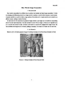
A. The Haar wavelet transform The Haar Wavelet Transform (HWT) [24] is one of the simplest and basic transformations from the space domain to a local frequency domain and it is a very useful tool for signal analysis and image processing. The HWT decompose a signal into different components in the frequency domain. Onedimensional HWT decomposes an input sequence into two components (the average component and the detail component) by applying a low-pass filter and a high-pass filter. In the HWT of 2D image of size NxN, a pair of low-pass and high-pass filters is applied separately along the horizontal and vertical direction to divide the image into four sub-bands of size N/2xN/2 (Fig. 1). After one level of decomposition, the low-
low-pass sub-band LL is the multiresolution approximation of the original image, and the other three are high frequency subbands representing horizontal, vertical and diagonals edges, respectively. The LL band is again subject to the same procedure.
Figure 1.
LL
HL
LH
HH
Thus, an image block D can be determined as belonging to smooth or heterogeneous type by using its vertical coefficient WVD and its horizontal coefficient WHD obtained by a pyramidal HWT at the highest level. The computation of WHD and WVD do not require the calculation of other wavelets coefficients. Indeed, let D be an image block of size 4x4 represented as follows:
1 5 9 13
The result of 2D image HWT decomposition.
This wavelet decomposition can be repeatedly applied on the low-low-pass sub-band at a coarser scale unless it only has one component as shown in fig. 2. Let D be a given image block of size NxN. D can be decomposed into one component low-pass signal by a log N/log 2 pyramidal HWT. In the case of N=8, D can be transformed to one component by 3 decomposition (Fig. 2). The LL3 band in level 3 is the multiresolution approximation of LL2 bands in level 2. The coefficients HL3, LH3 and HH3 of the highest level denote the coarsest edges along horizontal, vertical and diagonal directions respectively in level 2.
HL3
LH3
HH3
LH2
HL
HL1 HH2
HH1
We will refer to these coefficients obtained at the highest level hereafter as WHD for HL3, WVD for LH3 and HH3 for WDD. If both WHD and WVD are small, then the block D tends to have less edge structure (smooth block). When a block has high degree of edge structure, either WHD or WVD will be large. If WHD is larger, D will have horizontal edge properties. On the other hand, if WVD is larger, then D will have vertical edge properties. Finally, those blocks with high magnitudes of WHD and/or WVD are designed as heterogeneous domain blocks. The type of each block D is determined as follows: WH D