Available online at www.sciencedirect.com
Procedia Engineering 15 (2011) 964 – 968
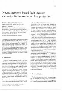
Advanced in Control Engineering and Information Science A Fault Location and Realization Method for Overhead High Voltage Power Transmission Jiang Zhen bao∗
Zhong Tingjian Ye Mao
(Jiang Xi Vocational˂Technical College Of Electricity ,Nanchang,330032,China) Abstract
The accurate fault location for high voltage transmission line plays increasingly important role in power systemˈso the development and general situation of the research in this field in China and in other countries is introduced in this paper. All the existing algorithms can be classified into three main methods: traveling wave location, single terminal location and two terminal location, the principle and application condition of each algorithm are presented and discussed. Base on the analysis and comparison of each algorithm, the corresponding merits and application limitation are concluded. At last, the prospects in fault location research are described in this paper. © 2011 Published by Elsevier Ltd. Open access under CC BY-NC-ND license.
Selection and/or peer-review under responsibility of [CEIS 2011]
Key words:
traveling wave, overhead transmission line, fault location algorithms
1.Introduction
For single-ended power supply line, from the fault of measured voltage and current of the electric resistance calculated by weight and bus lines to the point of failure is directly proportional to the length, and divided by the electric resistance per unit length on the value of fault distance which can be obtained. However, by the fault location precision resistors, transformer error, asymmetric line structure, line corridor terrain changes and the impact of distributed capacitance lines and also does not fit DC transmission lines, with series compensation capacitor circuits, T branch lines and some double-circuit lines disadvantage. National Power Company promulgated the« National Electric Power Dispatching System of the fifteen Technology Development Plan », The Traveling wave fault location method is based on : because of traveling wave in transmission lines have on the spread of fixed ---speed (close to the speed of light). According to this characteristic, if we able to measure and record line fault by the fault generated traveling wave bus arrival time, we can achieve accurate fault location. It is early in the 20th century, we began to study traveling wave devices ranging, but in that time, because of technical limitations, the early development of the traveling wave fault location device is very immature and there are bad reliability, complexity investment and other difficulty. So basically it had not been applied. With people research traveling wave line fault in-depth and microelectronics technology advances, the rapid development of computer technology in recent years, traveling wave fault location technology has made significant progress.
∗
Corresponding author. Tel.:+8613970828056
E-mail address:
[email protected]
1877-7058 © 2011 Published by Elsevier Ltd. Open access under CC BY-NC-ND license. doi:10.1016/j.proeng.2011.08.178
965
Jiang Zhen bao et al. / Procedia Engineering 15 (2011) 964 – 968
Ċ. THE PROPOSED CONTROL METHOD A. single-ended A-Range Way Line in the event of the fault of surveillance, fault wave generated electricity will be reflect between the point of failure and the bus. The installed Department Range device in the bus connect to the secondary side of current transformer of transient traveling wave signal, using analog or digital of high-pass filter can filter the pulse traveling wave, and as shown in Figure 1 of the electric traveling wave. Because of the bus impedance and line impedance difference, so the electric traveling wave at bus and fault points can be reflex, the reflex wave is synonymous in the point of failure and the initial fault traveling wave, and there is time difference Δt between the initial fault traveling wave pulse and the reflected point of failure, it is also correspond to the time that the traveling wave between at the point of failure and the bus trips once each other, so it can be used to calculate the fault distance. Hypothesis the initial fault traveling wave and reflected wave from the point of fault bus of time are respectively TS 1 ǃTS 2 ˈthe traveling wave velocity is υ (close to the speed of light, the specific depend on the lines of distribution parameters),So the fault distance( X S ) is calculated as follows:
1 1 X S = νΔt = ν (TS 2 − TS 1 ) 2 2
(1)
t
Δt
Fig.1 A-Range Way principle
B. Single-ended C-Range Way C-range way is mean that the pulse launcher launchs high-voltage and high-frequency or DC pulse to the offline of fault line ,according to high-frequency pulse from the device to the point of failure passing the time, it can be to calculate the fault distance. This device is easy, and higher accuracy ,for a long time it has been widely applied. As shown in Figure 2.
t=0 t
Δt
Fig.2 C-Range Way principle
C. pairs of terminal D-Range Way Hypothesis the length of line is Lˈline-wave velocity is
υˈ
The times of initial traveling wave
T T arriving to bus are respectively S and R ˈas shown in Figure 3. The devices installed in lines record time when the fault of traveling wave arrive at both ends of bus, then the distances of the point of fault to the bus(S and R) are respectively
X S = [(TS − TR )ν + L ]/ 2
XSǃ XR : and
X R = [(TR − TS )ν + L ]/ 2
(2)
Fig.3 D-Range Way principle
The method of two-terminal fault location detected only the initial traveling wave, it does not need to consider the follow-up reflection and projection of the traveling wave ,and principle is simple, date is reliable, but at both of lines end must be installed data acquisition and synchronization(GPS clock) devices, and at both sides also must be communicate, exchange recorded the initial fault line’s information ,this purpose is to detect the distance of fault accurately. If there is no automatic communication
966
Jiang Zhen bao et al. / Procedia Engineering 15 (2011) 964 – 968
device, we can use phone contact and artificial exchange to record the initial traveling wave’s time, so the fault of distance can be calculated to use of formula (2). However, when the detection of bus lines measured are open circuit, it will be not detected electric waves, so it will also lose the basis of location. III. THE COMPARISON OF SEVERAL METHODS Several methods of traveling wave fault can determine the point of fault by measuring the traveling wave passing through time in the lines. Generally speaking, a variety of location algorithms have their own advantages and disadvantages. A-type uses the least equipments, the front of end only needs with a high sampling rate of the collector; but D-type is equipped with the stability and good communication channel; and C-type needs pulse generator. From dealing with information, A—type is necessary to distinguish effective from the traveling wave coming to the point of failure or reflection -side bus, but as to D-type, because of using the point of fault which are generated to the first traveling wave, so it is easy to obtain signal and the above-mentioned problem does not exist; C-type by using of the point of failure which engenders first reflected wave, so there is also no that problem. From the measurement region, C-type and A-type also have the blind spot; but D-type has no blind spot problem. If there is zero voltage failure, so transient traveling wave is very weak, the A-type and D-type approach will be lapsed; but C-type has no this restriction. So A-type and D-type suit for transient (temporary) and permanent (continuous) line better, C-type only applies to permanent fault. With the development of communications and computer technology, two-terminal location method has broad prospects. Actually, even by using of GPS synchronous sampling, voltage and current transformer, as well as protection devices still have a certain delay about the transmission, so it is difficult to do data synchronization on the real meaning, but error allows at the range, two -terminal location will be also applied popular. IV. THE HARDWARE DESIGN This system is mainly composed of data analysis station, data acquisition and processing device and communication channel, analysis system and maintenance system, and so on. as shown in Figure 4.
Fig.4 Travelling wave system
Data acquisition and processing device is composed of the data acquisition unit and PC device. Data acquisition unit can be used to record fault traveling wave data, and PC device can read, save and deal with the data, and exchange with date from data analysis station or other substations, so it achieves two-terminal fault location. Data acquisition unit is main composed of three basic modules: central processing unit, high-speed data acquisition unit, GPS interface unit, as shown in Figure 5.
Fig.5 Data acquisition unit
A. Central processing unit Central processing unit is the core of the location device , it can realize electricity wave data storage and processing, human-machine interface and PC communication functions.
Jiang Zhen bao et al. / Procedia Engineering 15 (2011) 964 – 968
B. High-speed data acquisition unit High-speed data acquisition unit can detect electricity wave, collect and record fault data, and once completing a record, the fault data will be transmitted to the central processing unit. C. GPS interface unit GPS interface unit can transmit time information to the devices by GPS synchronized clock provided, and at the same time it records the fault traveling wave to reach the initial pulse taking time, and tests results to transmit to the central processing unit. V. SIMULATION RESULTS At present, We will compare the results with software and the actual results. At 17:55 on July 24, zero-sequence I paragraph moves at 110kV Taihe transmission line, the actual point of fault found from Taihe substation is about 13.56km. But using software analysis of the distance is 13.3km from Taihe substation, so the difference is 260m.as shown in figure 6.
Fig.6 Simulation results
Let us look at 6:05 on October 11, zero-sequence I paragraph moves at 110kV Taihe transmission line, then the success of reclosing, the actual point of fault found from Taihe substation is about 11.78km. But using software analysis of the distance is 11.3km from Taihe substation, so the difference is 480m, as shown in figure 7.
Fig.7 Simulation results
Because of the success of fault superposition, superposition is also to react in the device. As shown in figure 8.
Fig.8 Simulation results
967
968
Jiang Zhen bao et al. / Procedia Engineering 15 (2011) 964 – 968
At this time we can see that the total length of lines is 68.0km, The difference is 500m with our original data measured (68.5km). From the above comparisonˈwe can list table as follows: Table.1 Date analysis
Date Actual distance Software analysis July 24 13.56km 13.3km October 11 11.78km 11.3km October 11 68.5km 68.0km (after fault Superposition)
Difference 260m 480m 500m
It shows that the traveling wave fault location device has high precision, fast and accurate fault location, and it can also shorten time for repair. Using this device, on the one hand, it greatly improves the Jinggangshan, Suichuan city and other substations power supply reliability, especially, it is very important to ensure Jinggangshan power supply job, on the other hand, it can reduce the power loss. Therefore, there are remarkable economic and social benefits. VI. Conclusions High voltage transmission line fault location has great significance and engineering practical value, With the development of computer communications technology and microprocessor -based protection devices in power system a wide range of applications. Implementation of overhead high voltage transmission line fault location has become possible. Traveling wave method has the reliability and accuracy, in theory, it is not affect to line type, fault resistance and the impact of devices on both sides of the system, so it is a hotspot studies early. Recently, with the increasing size of power system , voltage level constantly improvement, power grids becoming increasingly complex, in order to guarantee system security and stability, so people do a lot of research on phase pattern transform, frequency conversion parameters and transient numerical calculation, as a result, we deeply know of the traveling wave method and many related factors, in particular, wave theory and global satellite positioning system ( GPS, global positioning system) emerged, thereby they greatly enhance the transient traveling-wave signal extraction efficiency, simplify data synchronization at both ends of the process, improve the location accuracy, which bring traveling wave fault location to have some new prospects. REFERENCES [1] Xu Bingyin, modern traveling wave fault location technology and applications. Power system automation, 2001, (23) [2] LI Youjun, several traveling wave fault location algorithms comparison. Power system automation, 2001,(14) [3] Dong Zhenhe, transmission line traveling wave fault location. Shandong Electric Power Technology, 2000, (02) [4] Chen Ping, based on fault transient traveling wave breaking information fault location studies on transmission line. Journal of Electrical Engineering of Chinese .2000 [5] YuYusheng, Yang Minzhong, Li Xiaobing and so on, high-voltage overhead transmission line fault location methods [J]. electricity web technology, 2000,24 (4) [6] Dong Xinzhou. Wavelet theory is applied in fault location of transmission lines [D]. Xi'an Jiaotong University, 1996 [7] Chen Ping, Xu Bingyin, Li Jing. Modern traveling wave fault location device and its operation experience [J]. The power system automation, 2003,27 (6) [8]Wu Dali, Yin Xianggen,Zhang Zhe. Hardware and design of traveling wave fault location system [J]. Relays, 2006,34 [9] Chen Yunping, Gong Qingwu.An Accurate Fault Location for Transmission Line Using Local and Remote Signals. Proceeding of IPEC.1997, Vol.2, PP605-609 [10] Mallat S, Hwang W L. Singularity Detection andProcessing with Wavelets.IEEE Trans on Information Theory, 1992