A Fault-Tree Semantics to model Software-Controlled Systems Bernhard Kaiser Hasso-Plattner-Institute for Software Systems Engineering at the University of Potsdam, Dept. for Software Engineering and Quality Management, Prof.-Dr.-Helmert-Str. 2-3, Potsdam email:
[email protected]
Abstract Fault Tree Analysis is a very popular technique to assess safety and reliability of technical systems. However, being a combinatorial model, Fault Trees can only express which combinations of failures contribute to a certain hazard or accident. There is no means to model sequences of actions and temporal orders of states and events. Since today technical systems are often controlled by software that executes over time, the traditional Fault Tree model is no longer sufficient. Moreover, integration of software modelling techniques with safety assessment techniques is hampered by the lack of semantically equivalent entities in both domains. To overcome these drawbacks, we propose an extended Fault Tree semantics that distinguishes events that happen at a point in time from states that last over a period of time. Typed Fault Tree gates are introduced and calculation rules for quantitative analysis are given. We address the integration of this new concept into our Safety and Reliability Analysis Tool UWG3.
Keywords Safety and Reliability Analysis, Fault Tree Analysis, Embedded Systems
1
Introduction
Today most technical systems contain microprocessors and software. Due to their complexity they can only be understood with the aid of models that capture their structure and behaviour. Modelling techniques should offer a formally defined syntax to be unambiguous and a graphical notation for intelligibility. Formally defined semantics allows automated code generation, verification of code against its specification or validation of a specification, e.g. by simulation. State/event models, for instance Statecharts [Har87], are widely used for control aspects. Many technical systems are safety or reliability critical, e.g. in the domains of transportation or industrial control. Among the evaluation methods for safety and reliability, Fault Tree Analysis (FTA) is a widely accepted technique. It graphically shows how basic failures in combination cause a hazard or an accident on system level. Unfavourably, Fault Trees do not offer a way to express sequences of actions and temporal orders of states and events. For that reason, they are not always best choice to model the failure mechanisms of soft-
ware-controlled systems. Moreover, the lack of common terms uniting software models and Fault Trees inhibits the integration of system design and safety analysis [FMcD93],[Kai02]. Safety analyses cannot be generated automatically from software engineering artefacts as often considered desirable [LR98]. To overcome these problems we propose to extend the Fault Tree semantics by a notion of states that last over a time interval and events that happen instantaneously. This concept offers two advantages: on the one hand temporal ordering and duration can now be modelled accurately and on the other hand the gap to software design models is bridged by the common notions associated to the terms in both worlds. As a consequence, we furnish Fault Tree gates with typed inputs (state inputs or event inputs) and outputs. Sometimes we have to map one traditional gate to more than one gate of our new notation. We show how to perform probabilistic analysis on these extended Fault Trees and reach results that are compatible to Markov analysis results of the same system. Chapter 2 of this paper gives an overview about Fault Tree analysis, its deficiencies and research efforts to overcome them. In chapter 3 we introduce our extended Fault Tree semantics and give the calculation rules for quantitative analysis. In chapter 4 we tell about practical applications and compare our solution to an equivalent Markov chain based solution. In chapter 5 we conclude with a perspective on our future research activities.
2 2.1
State of the Art and Previous Work
Safety and Reliability Analysis Several safety and reliability assessment techniques are in use. They have in common that they estimate the probability for some undesired event to occur. Some of them are rather informal, for instance FMEA. The more formal ones can be divided into state-based models, such as Markov Chains, and combinatorial models, such as Fault Trees. Fault Trees [IEC 61025],[Ves+81] are a widely accepted model that graphically shows how influence factors (faults or failures) contribute to some hazard or accident. They provide logical connectives (called gates) that allow decomposing the system-level hazard recursively into its influence factors. Traditionally, the connectives are constrained to propositional logic (AND-, OR-, NOT-gate). The logical structure is depicted as an upside-down tree
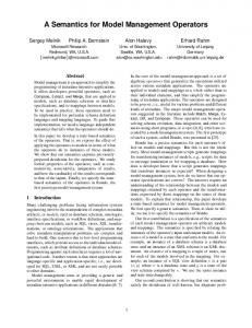
with the hazard (called top-event) at its root. An example is given below. Some steam boiler explodes if the pressure sensor or the safety valve is defective and the pressure exceeds the critical level. Steam Boiler explodes
&
>=1 Pressure exceeds critical level Safety Valve Pressure sensor stuck closed defective
Fault Trees can be analysed qualitatively, e.g. in order to find critical parts of the system, or quantitatively. In the latter case, a probability distribution over time is assigned to each basic failure event. A set of rules allows calculating the failure probability or unavailability of the whole system out of the given probabilities. FTA historically stems from the age of mechanical and non-programmable electronic systems. In this context, the main cause for failure is wearout. A unit is either functional or defective and once defective it will not fail a second time. All basic and intermediate events in FTA are failure events. The Fault Trees are generally coherent, i.e. in any situation, failure of yet another part can only further decreases the availability of the system. 2.2
Software Controlled Systems For the last two decades, software controlled systems have been replacing mechanical or electronic parts in many areas of our daily life. They execute threads of control sequentially or concurrently and do not have statically determined laws of control such as cogwheels, levers or electric relays have. Thus, they have very different failure behaviour than traditional technical systems. Failures may evolve as chains of actions - or omissions. Furthermore, software controlled systems are involved in areas where a stable safe state is not reachable and continuous active control is required, e.g. in aviation or car steering systems. Systems involved in accident prevention, for instance airbag controllers, must react in a timely fashion on requests and the equation 'doing nothing is doing nothing wrong' is no longer true. Another aspect often encountered in the
context of software systems is robustness that is achieved by checks for deviation from normal input. This betters the system safety and should be captured by a model. For the safety assurance of software, other methods than the traditional safety models have been proposed. Mainly these are formal methods such as theorem proving and model checking. Instead of dealing with probabilities they claim to prove absolute correctness. However, we believe that there are several reasons to make the probabilistic safety analysis techniques applicable for software systems, too. First, the mentioned methods check isolated parts of the software under the assumption of an ideal environment. Hardware, timing, concurrency or human operator aspects are often left aside. Second, the software manufacturing process today is not mature enough to assure that a proven algorithm actually leads to a acceptable final product. Third, formal methods rely on formal specifications, but these are difficult to generate. It is not guaranteed that the specification correctly and completely describes the real world system and its environment. Last and most important, an integrated analysis of the complete technical system is desirable, since accidents happen in the real world and non-software parts are necessarily involved.Nevertheless, formal techniques from software engineering have added more semantic precision to system analysis and the formal models of the software form a valuable base for system safety analysis. Therefore, our research project tries to extend and to adapt Fault Tree Analysis for software systems and to integrate it with other software models [Kai02]. 2.3 Deficiencies of Fault Tree Analysis in the context of Software Controlled Systems Software Controlled Systems are often described in terms of states and events. External events in the environment or timer events trigger state transitions of the software. The software changes to a new state, where another law of control is valid, or it provokes actions that influence the rest of the system or the environment. In the context of FTA, a first misunderstanding arises from the term 'event'. In FTA, as in probability theory, the term event means a result of a random experiment, e.g. when rolling dice, that the number 6 shows up. So in reliability engineering the fact that some technical component is found in failed state is an event. In software engineering, the term 'event' usually refers to something that happens instantaneously; something that persists is called a state. For the behaviour (and failure) of software systems the order, in which events occur, is often relevant. In some cases also the time between the occurrences of two events is of importance. Fault Trees only represent the system at a given point of time. Software systems can be in many different states and only the context and the further evolution
determine whether these are "good" ones or "bad" ones. Fault Trees by definition only deal with faults and failures. In FTA, there are exactly two states for each component, healthy and defective.
only one event can occur throughout the system. Probabilistically, each event has an associated probability density p(t). It is defined by
Critical software systems offer error coverage and correction mechanisms. A protective part can, as long as it is active, prevent failures from other parts to propagate to the environment. To model this situation, an INHIBIT gate with implicit state/event semantics has been introduced in FTA.
(3-1)
2.4
Previous Work During the last decade several researchers have addressed the mentioned issues. There have been several attempts to define Fault Trees for Software [Lev+91]. Some proposals derive Fault Trees from state machine models [LR98] or other software engineering artefacts. [STR02] integrate Fault Trees with formal program specifications and use Interval Temporal Logic (ITL) to give a formal semantics to Fault Trees. As [Gor94] they distinguish between causation and generalisation semantics. Some authors have mapped Fault Trees to Petri Nets [Buc00],[Gor+95] or Markov Chains [Cop00]. Interestingly, different authors have proposed different Petri Net equivalents to the same Fault Tree gates. Some researchers [Gor94],[Cop00] have noticed the need for additional Fault Tree gates, for instance describing conditional probability, sequence enforcing, various spare usage situations or flip-flop behaviour. [FMcD],[Blo+91] have been working towards an integrated framework for embedded systems modelling and safety / reliability analysis. We have semantically analysed and compared the proposals mentioned above and many of them gave valuable input to our work. However, to our knowledge nobody has yet proposed an approach using states and events and typed gates for FTA to match software models.
3
Fault Trees with Dynamic Gates
3.1
The Semantics of States and Events In the following the basic terms of our framework and the corresponding probabilistic measures are defined. Time is assumed to be continuous, i.e. t∈ú0+. State applies to anything that has a duration. When dealing with one particular deterministic system, a state term is either true or false in each point in time. When considering a very large set of similar systems or a probabilistic system, a probability P(t)∈[0,1] can be assigned to each state in each point of time. Event applies to any phenomenon that happens in one point of time and has no duration. This can be a state transition in the system, an external trigger or a certain point in time. In our model it is allowed that events occur more than once during the lifetime of a system. We assume that in a very short time interval
pe (t ) = lim
∆t →0
Pe (t , t + ∆t ) ∆t
where Pe(t1,t2) denotes the probability that event e occurs in the time interval [t1, t2). If an event is a transition from a state Si to another state Sj, then the transition rate or rate λ(t) is defined as the conditional probability that the component changes from Si to Sj within the next small time interval, provided that at time t it is in Si: (3-2)
λe (t ) = lim
∆t → 0
ij
P(S (t + ∆t ) = S j S (t ) = Si ) ∆t
,
where eij is the transition event from Si to Sj. Both probability density and rate have the dimension 1/time. There is no commonly accepted graphical notation for states and events in Fault Trees, so we will use in the following for states (cf. "State Charts")
for events (cf. "Petri Net Transition").
3.2
3.2.1
The Semantics of Fault Tree Gates
Different Classes of Gates
To build a Fault Tree with states and events, the analyst starts by choosing a top-event or a top-state. An accident (that happens suddenly) is a top-event, a hazard situation (that lasts over a period of time) is a top-state. As with traditional Fault Trees, this top-event or state is decomposed using Fault Tree gates. Gates have typed inputs and outputs. The input or output of a gate may be either a state or an event. Analysis tools should check consistency, i.e. a state input must not be connected to an event output and vice versa. Due to the type system there are more gates than in traditional FTA. Note that the intermediate and basic terms (states or events) need not be failures as such: It is possible that only in combination with other facts or only when occurring in a certain order these states or events contribute to the top term. The Fault Tree need not be coherent; it may be that a component being in a certain state or a certain event prevents an accident. We classify the gates of our framework into the following families: 1.
The NOT gate which has one state input and one event output. There is no simple negation of events.
2.
3.
4.
5.
The OR gates between states or between events. There is no OR gate that mixes states with events. The AND gates between states and/or events. There is no simple AND between two events, only particular forms such as History-AND or Sequential-AND.
>=1
Converting gates that are necessary to match state inputs to event outputs and vice versa.
Mechanical Impact
Special gates such as conditional probability or delay.
In the following section we will take a closer look at some of the different types of gates and demonstrate their use by practical examples.
3.2.2
Controller stops working
OR-Gates There are two OR gates:
a) OR: state × state → state
The equation for the output probability density is: (3-4)
>=1
pout = pin1 + pin 2
The probability densities are simply added since, by assumption, no two events happen in the same small time interval.
3.2.3 PC is defective
Overvoltage Pulse
AND-Gates
There is one AND-gate that joins two or more states and one that joins a state with an event. Unlike in standard FTA there is no AND that joins two or more events. This is due to the assumption that in continuous time, no two events occur simultaneously. Instead there are two kinds of AND-gates with history memory, one, in wich the order of the occurrences of the input events is relevant and one where it is not. a) AND: state × state → state Laptop is unavailable
Hard Disk is CPU is defective defective
This gate has generalisation semantics: The output state can be regarded as a collective alias for the input states. The equation for the probabilities is: (3-3)
&
Pout (t ) = 1 − ((1 − Pin1 (t )) * (1 − Pin 2 (t ) ))
provided that the input states are stochastically independent. Power Supply is defective
b) OR: event × event → event This gate can either have causation semantics (as in the example) or generalisation semantics. Causation means that occurrence of any of the input events necessarily causes the output event to occur. From analysis point of view this makes no difference, since we assume that the effect follows the cause immediately, unless a delay is explicitly modelled.
Battery is empty
This gate has generalisation semantics. The equation for the probabilities is: (3-5)
Pout (t ) = Pin1 (t ) * Pin2 (t )
again under the assumption of stochastic independence. b) AND: state × event → event
This formula suits well for numerical analysis. Boiler explodes
d) Sequential-AND: event × event → event
&
Pressure exceeds critical level
Safety Valve is defective
This gate models situations where the input events must occur in a certain order to trigger the consequential event at the output. Suppose, for instance, that a steam boiler explodes if the pressure exceeds some critical level after the safety valve has got stuck. No accident would happen if the events occurred the other way around. Clearly, this gate has causal semantics as well.
This gate would be appropriate for the situation described in the introduction chapter: If a certain event happens while the system is in a given state, then immediately after the output event happens. The equation for the probability and probability densities is: (3-6)
Boiler explodes
Sequential &
pout (t ) = pin.event (t ) * Pin.state (t )
1
2
c) History-AND: event × event → event The History-AND gate has a causal semantics and models the fact that its output event occurs immediately after the last of its input events has occurred, provided that all other input events have occurred before. The input events may occur in any order. Metal plate falls off
Pressure Safety Valve gets exceeds critical level stuck
The calculation is very similar to the HistoryAND gate, but this time only the case where the first input event occurs before the second one is considered: (3-8)
History &
Left bolt breaks
Right bolt breaks
To calculate the output probability density we assume that each of the input events occur only once in the lifetime of the system. There are two possibilities that the output event occurs in the next small time interval ∆t: either the first input event had occured in the past and the second occurs in this next interval, or the second one had occurred before and the first one occurs now (remember the assumption that no two events occur at the same time instant). The probability that the output event occurs in the next small time interval ∆t is: (3-7)
pout (t ) = Pin1 (0, t ) * pin.2 (t ) + Pin2 ( 0, t ) * pin1 (t )
3.2.4
pout (t ) = Pin1 (0, t ) * pin.2 (t )
Converting Gates
A state input cannot be connected to a state output or vice versa. However, there are situation where the modeller may want connect an event to a state. The passage from an event to a state has the meaning of referring to the state after the event has happened for the first time. The passage from state to event has the meaning of referring to the point in time where the state is entered. At the current state of our work we restrict these transformations to the case where an event occurs at most once during the mission-time of a system. This assumption holds for failure events in non-repairable systems. Further we assume a numerical time-discrete solution, as performed by our tool UWG3. The gate that performs the passage from a state to an event numerically differentiates the probability of the state at input to get the probability density at output. We call it "On-Entering-gate".
Boiler explodes
ON ENTERING
Pressure is higher than critical level
Its equation for numerical analysis is: (3-9)
pout (t ) =
Pin (t + ∆t ) − Pin (t ) ∆t
where ∆t is a small time interval.
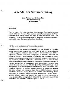
ple point, the given formulae are applied to get the probability density of each intermediate event or the probability of each intermediate state. Integration is replaced by summation. In the end, the unavailability of the system or a hazard probability over time can be calculated. If an accident or failure event is at the top of the fault tree, its probability density or rate is the result of the analysis. Maximum and average rate can be calculated, as well as the probability that the system survives a certain mission time. Practical Application and Experiences We have successfully carried out some small case studies where we used Microsoft Excel as a numerical simulation and plotting tool. Our examples consist of just one gate. The main purpose is to prove the consistency to other models, mainly Markov chains. For the case of exponentially distributed events, we have compared our History-AND gate (see example above) to an equivalent Markov Chain (see figure below)and found the same results for the failed state. We did the same comparison with our Sequential-AND gate and a corresponding Markov chain.
The reverse transformation gate is called "UPON-gate".
λ1
Valve is stuck closed
Some mechanical part in valve breaks
It numerically integrates the probability density at the input: (3-10)
3.2.5
Pout (t + ∆t ) = Pout (t ) + pin (t ) * ∆t Complex Gates
For convenience it is possible to define other gates by representing them as a structure of simple gates. For instance, the inhibit gate can be defined as a structure of an AND gate (state+event) and a NOT gate (state). Other such gates are XOR or Voter gates. The collection of gates offered by a practical tool should rather be a convenient one than a minimal one. 3.3
Quantitative Analysis Our current analysis approach works numerically. The mission-time of the system is covered by an adequate number of sample time points. For each sam-
λ2 both bolts broken
both bolts ok λ2
UPON
left bolt broken
right bolt broken
λ1
The integration of our new concept into our Safety and Reliability Analysis Tool UWG3 is ongoing. UWG is a modular Fault Tree Analyser that will later be extended to an integrated workbench for system modelling and safety analysis. Thanks to its Component Fault Tree concept [KLM03] we expect even complex systems to be manageable and the numerical analysis to complete in reasonable time on standard PCs. Another problem we are currently working on is the stochastic dependency between several intermediate states and events. We are carrying out experiments with Multi-valued Decision Diagrams to solve this issue. These are at the same time a promising approach to model multi-state components. In computer systems there are some kinds of events that may occur more than one time during the mission time of a system. In this case, transformation to Petri Nets or simulation are suitable means to produce the correct solution.
4
Conclusion and Future Work
We have presented our approach to extend Fault Trees to model computer controlled systems by introducing a distinction between states and events (in the sense of instantaneous phenomena). This concept not only formalises the semantics of Fault Trees, but it
also extends the expressive power of FTA to model temporal ordering of events. Due to the common terms state and event in FTA and in software engineering models it is easier to find a mapping between both and to automate the generation of safety analyses from existing documents. The concept will need further improvements and validation by larger-scale case studies. The gates proposed here are not yet sufficient to model all situations that arise in software-controlled systems. Thus we intend to add some new gates to our framework, for instance History-AND with a Reset input or HistoryAND with a time parameter, indicating that the output only occurs if both input events happen within a given time interval. As soon as the integration into our tool UWG3 will be completed, a combination with a Markov analyser is planned. Later on we plan to import CASE tool models and to derive safety-analyses partly automatically. This will take us closer to our final research goal of establishing a workbench that allows integrated safety and reliability analysis during the design process of embedded systems.
References [Buc00]
Kerstin Buchacker. Definition und Auswertung erweiterter Fehlerbäume für die Zuverlässigkeitsanalyse technischer Systeme. Technical Report 33/3, FriedrichAlexander-Universität Erlangen-Nürnberg, Institut für Informatik, 2000 [Blo+91] E. Bloomfield, J. H. Cheng, J. Górski, Towards A Common Safety Description Model, Proceedings of the 10th International Conference on Computer Safety, Reliability and Security SAFECOMP'91 (Edited by J. F. Lindeberg), pp. 1-6, Pergamon Press, 1991 [FMcD93] Fenelon, P., McDermid, J.A., (1993), An Integrated Toolset For Software Safety Analysis, Journal of Systems and Software, 21(3): p. 279-290 [GMW95] Górski J., Magott J. and Wardziński A., Modelling Fault Trees Using Timed Petri Nets, Safecomp'95, Villa Carlotta, Belgirate, Italy, 11-13 Oct. 1995
[Gor94]
Górski, Extending Safety Analysis Techniques with Formal Semantics, In Technology and Assessment of Safety Critical Systems (Edited by F.J. Redmill and T. Anderson), Springer Verlag, 1994 [Harel87] David Harel: Statecharts: A Visual Formulation for Complex Systems. Science of Computer Programming 8(3): 231-274 (1987) [IEC61025] International Standard IEC 61025: Fault Tree Analysis. IEC, Geneva, 1990 [Kai02] Integration von Sicherheits- und Zuverlässigkeitsmodellen in den Entwicklungsprozess Eingebetteter Systeme. Softwaretechnik-Trends 22(4): (2002) [KLM03]
Kaiser, B., Liggesmeyer, P., Mäckel, O.: A New Component Concept for Fault Trees. Submitted to the 8th Australian Workshop on Safety Critical Systems and Software, Canberra, 9-10 October 2003 [LR98] Liggesmeyer P., Rothfelder M., Automating Reliability and Safety Analysis Based on Formal System Models, in: Proceedings International Conference and Workshop: Engineering of Computer Based Systems, Jerusalem, March/April 1998, pp. 264 - 271 [Man+98] R. Manian, J.B. Dugan, D. Coppit and K.J. Sullivan, “Combining Various Solution Techniques in Dynamic Fault Tree Analysis,” Proceedings of the High Assurance Systems Engineering Symposium, 1998, pp. 21--28 [PM01] Yiannis I. Papadopoulos and Matthias Maruhn.Model-Based Synthesis of Fault Trees from Matlab-Simulink Models. Proceedings International Conference on Dependable Systems and Networks (DSN-2001), Göteborg, Sweden, June 30th - July 4th, 2001 [STR02] Gerhard Schellhorn, Andreas Thums, Wolfgang Reif. Formal Fault Tree Semantics. Integrated Design and Process Technology (IDPT) 2002 [Ves+81]
Vesely, W. E., Goldberg, F. F., Roberts, N. H.,. Haasl, D. F.(1981) Fault Tree Handbook. U. S. Nuclear Regulatory Commission, NUREG-0492, Washington