6 method invocations, initializing of attributes, exception handling, etc (Colyer et al., 2004). A ... ATLAS INRIA & LINA research group (ATL-User-Guide, 2009).
1 Using Model Transformation Language Semantics for Aspects Composition Samuel A. Ajila, Dorina Petriu and Pantanowitz Motshegwa Department of Systems and Computer Engineering, Carleton University, Ottawa, ON, Canada
1. Introduction Modern software systems are huge, complex, and greatly distributed. In order to design and model such systems, software architects are faced with the problem of cross-cutting concerns much earlier in the development process. At this level, cross-cutting concerns result in model elements that cross-cut the structural and behavioral views of the system. Research has shown that Aspect Oriented (AO) techniques can be applied to software design models. This can greatly help software architects and developers to isolate, reason, express, conceptualize, and work with cross-cutting concerns separately from the core functionality (Ajila et al., 2010; Petriu et al, 2007). This application of AO techniques much earlier in the development process has spawned a new field of study called AspectOriented Modeling (AOM). In AOM, the aspect that encapsulates the cross-cutting behavior or structure is a model, just like the base system model it cross-cuts. A system been modeled has several views including structural and behavioral views. Therefore, a definition of an aspect depends on the view of interest. Unified Modeling Language (UML) provides different diagrams to describe the different views. Class, Object, Composite Structure, Component, Package, and Deployment diagrams can be used to represent the structural view of a system or aspect. On the other hand, Activity, State Machine, and Interaction diagrams are used to model the behavioral view. Interaction diagrams include Sequence, Interaction Overview, Communication, and Timing diagrams. After reasoning and working with aspects in isolation, the aspect models eventually have to be combined with the base system model to produce an integrated system model. This merging of the aspect model with the base model is called Aspect Composition or Weaving. Several approaches have been proposed for aspect composition using different technologies/methodologies such as graph transformations (Wittle & Jayaraman, 2007), matching and merging of model elements (Fleury et al., 2007), weaving models (Didonet et al., 2006) and others. The goal of this research is to compose aspect models represented as UML sequence diagrams using transformation models written in Atlas Transformation Language (ATL). Composing behavioral models (views) represented as UML Sequence diagrams is more complex than composing structural views. Not only is the relationships between the
4
Semantics in Action – Applications and Scenarios
model elements important but the order is equally paramount. Several approaches have been proposed for composing behavioral aspects with core system behavior, and these include graphs transformations [Whittle et al., 2007] and generic weavers [Morin et al., 2008]. In this research work we view composition as a form of model transformation. Aspect composition can be considered a model transformation since it transforms aspect and primary models to an integrated system model. Toward this end, we propose and focus on an approach that uses model transformations to compose both primary and aspect models represented as UML Sequence diagrams (SDs). SDs modeling the primary model and generic aspect models is created using Graphical UML modeling tools like Rational Software Architect (RSA). Model transformations are then used to instantiate the generic aspect models in the context of the application to produce context specific aspect models. Binding rules used for instantiating the generic aspect are represented as mark models that conform to a metamodel. Using other model transformations, the context specific aspect models are then composed with the primary model to produce an integrated system model. Verification and validation is performed, not only to verify that composition was successful, but also to ensure that the composed model is a valid UML model that can be processed further and shared with other researchers. The rest of this chapter is structured as follows. Section two presents Model Driven approach, Aspect-Oriented techniques and technologies, and Atlas Transformation Language (ATL). We present our approach to model composition in section three starting with an example. We introduce our model composition semantics and definitions in section four – giving formal notions and three major algorithms (pointcut detection, advice composition, and complete composition) that define the basis of our work. Section five presents the design and implementation of our model composition using ATL semantics. We introduce and analyze a case study based on phone call features in section six. Section seven gives our conclusion, limitations, and future work.
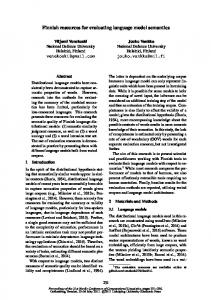
2. Model Driven Engineering/Development/Architecture (MDE/MDD/MDA) In Model Driven Engineering (MDE) everything is a model. A model refers to a simplified view of a real world system of interest; that is, an abstraction of a system. MDE considers models as the building blocks or first class entities (Didonet et al, 2006). A model conforms to a metamodel while a metamodel conforms to a metametamodel. MDE is mainly concerned with the evolution of models as a way of developing software by focusing on models. With this new paradigm of software development, the code will be generated automatically by model to code transformations. Model Driven Development (MDD) is copyrighted term by Object Management Group (OMG). One of the most important operations in MDE/MDD is model transformation. There are different kinds of model transformations including model to code, model to text, and model to model. Our interest in this paper is in model to model transformations. Figure 2.1 shows the process of model transformation. Since every artifact in MDE is a model, the model transformation is also a model that conforms to a metamodel. The transformation model defines how to generate models that conform to a particular metamodel from models that conform to another metamodel or the same metamodel. In Figure 2.1, the transformation model Mt transforms Ma to Mb. Mt conforms to MMt while Ma and Mb conform to MMa and MMb respectively. The three metamodels conform to a common metametamodel MMM.
Using Model Transformation Language Semantics for Aspects Composition
5
Fig. 2.1. Overview of Model Transformation Adopted from (ATL-User-Manual, 2009). OMG's Model-Driven Architecture (MDA) is a term copyrighted by OMG that describes an MDE approach supported by OMG standards; namely, UML, Meta-Object Facility (MOF), MOF-Query/View/Transformation (QVT), XML Metadata Interchange (XMI) and Common Warehouse Metamodel (CWM). MDA decouples the business and application logic from the underlying platform technology through the use of the Platform Independent Model (PIM), Platform Specific Model (PSM) and model transformations. The PIM describes a software system independently of the platform that supports it while PSM expresses how the core application functionality is realized on a specific platform. Given a specific platform, the PIM is transformed to PSM. Platform in this case refers to technological and engineering details that are independent of the core functionality of the application. For example, middleware (e.g., CORBA), operating system (e.g., Linux), hardware, etc. 2.1 Aspect-Oriented (AO) techniques/technologies The size of modern software systems has increased tremendously. Software architects and developers have to design and develop systems that are not only enormous, but are more complex, and greatly distributed. These systems naturally have many cross-cutting concerns (requirements) whose solutions tend to cross-cut the base architecture and system behavior. Such concerns include security, persistence, system logging, new features in software product lines, and many others. Aspect-Oriented techniques allow software developers and architects to conceptualize and work with multiple concerns separately (Groher & Voelter, 2007; Kienzle et al., 2009; Petriu et al., 2007). These techniques allow us to modularize concerns that we cannot easily modularize with current Object-Oriented (OO) techniques (Whittle & Jayaraman, 2007). The final system is then produced by weaving or composing solutions from separate concerns (Petriu et al., 2007). Klein et al. point out that dividing and conquering these cross-cutting concerns also allows us to better maintain and evolve software systems (Klein et al., 2007). Aspect Oriented Programming (AOP) applies AO techniques at code level (France et al., 2004; Petriu et al., 2007). AOP was introduced to enhance Object-Oriented Programming to better handle cross-cutting concerns that cause code scattering and tangling, which leads to code that is very difficult to maintain and impossible to reuse or modify. AOP addresses these issues by introducing a class like programming construct called an aspect which is used to encapsulate cross-cutting concerns. Just like a class, an aspect has attributes (state) and methods (behavior). An aspect also introduces concepts well known to AO community; namely, join points, advice, and pointcut. Join points are points in the code where the crosscutting behavior is to be inserted. AspectJ (a popular AOP Java tool) supports join points for
6
Semantics in Action – Applications and Scenarios
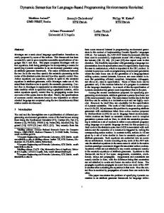
method invocations, initializing of attributes, exception handling, etc (Colyer et al., 2004). A pointcut is used to describe a condition that matches join points, that is it is a way of defining join points of interest where we want to insert the cross-cutting functionality. This crosscutting behavior to be inserted at a join point is defined in the advice. AspectJ supports before, after, and around advices (Colyer et al., 2004). Recent work in AO has focused on applying AO techniques much earlier in the development process (Kienzle et al., 2009; Klein et al., 2007; Morin et al., 2008; Petriu et al., 2007). In Aspect Oriented Modeling (AOM), Aspect-Oriented techniques are applied to models (unlike AOP). Whittle et al. define an AO model as “a model that cross-cuts other models at the same level of abstraction” (Whittle et al., 2006). Aspects are considered models as well; hence, it makes sense to define (or abstract) other concepts such as pointcuts and advices as models. However, the precise definition of a joint point, pointcut or advice depends on our modeling view. For example, in a structural view, such as a class diagram, an aspect is defined in terms of classes and operations/methods whereas in a behavioral view, such as a sequence diagram, an aspect is defined in terms of messages and lifelines. This has resulted in several approaches to AOM most of which have focused on separation and weaving (composition) of structural (class diagrams) and behavioral views (sequence, activity, and state diagrams) (Klein et al., 2007; Morin et al., 2008; Petriu et al., 2007). Several approaches have been proposed for composing aspects in AOM. These include using graph transformations (Gong, 2008; Whittle & Jayaraman, 2007), semantics (Klein et al., 2006), executable class diagrams (ECDs), weaving models (Didonet et al., 2006), generic approaches and frameworks (Fleury et al., 2008; Morin et al., 2008), etc. Composition primarily involves deciding what has to be composed, where to compose, and how to compose (Didonet et al., 2006). Aspect composition can either be symmetric or asymmetric. In symmetric composition, there is a clear distinction between the models to be composed; that is, one model plays the role of a base model while the other is declared an aspect model (Jeanneret et al, 2008). This distinction is absent in asymmetric composition. 2.2 Atlas transformation language The Atlas Transformation Language (ATL) is a model transformation language from the ATLAS INRIA & LINA research group (ATL-User-Guide, 2009). The language is both declarative and imperative, and allows developers to transform a set of input models to a number of output target models. In ATL, source or input models can only be navigated but cannot be modified (Jouault & Kurtev, 2005) whereas target models are write-only and cannot be navigated. Figure 2.2 below shows an overview of an example of an ATL transformation (Family2Person) from [ATL_Examples] that transforms a Family model to a Person model. The Family model conforms to an MMFamily metamodel whereas the Person model conforms to an MMPerson metamodel. The ATL, MMFamily, and MMPerson metamodels all conform to the Ecore metametamodel which is a metamodel for the Eclipse Modeling Framework. Families2Persons.atl is an ATL model or program that transforms a Family model to a Person model. ATL has three types of units that are defined on separate files (ATL-User-Guide, 2009); namely, ATL modules, queries and libraries. ATL has types and expressions that are based on the Object Constraint Language (OCL) from OMG. ATL has primitive types (Numeric, String, Boolean), collection type (sets, sequences and bags) and other types, all of which are
Using Model Transformation Language Semantics for Aspects Composition
7
Fig. 2.2. Overview of the Family to Person ATL Transformation. sub-types of the OCLAny abstract super-type. An ATL module or program, like Families2Persons.atl in the previous example, defines a model to model transformation (Jouault & Kurtev, 2005). It consists of a header, helpers (attribute and operation helpers) and transformation rules (matched, called and lazy rules) (Jouault & Kurtev, 2005). The header defines the module's name, and the input and target models. ATL operation helpers are more like functions or Java methods, and can be invoked from rules and other helpers. Attribute helpers unlike operation helpers do not take any arguments. All helpers are, however, recursive and must have a return value. Rules define how input models are transformed to target models. They are the core construct in ATL (Jouault & Kurtev, 2005). ATL supports both declarative and imperative rules. Declarative rules include matched rules and lazy rules. Lazy rules are similar to matched rules but can only be invoked from other rules. A matched rule consists of source pattern and target pattern (Jouault & Kurtev, 2005). A source pattern is defined as an OCL expression and defines what type of input elements will be matched (ATL-User-Guide, 2009). An ATL model is compiled, and then executed on the ATL engine that has two model handlers; namely, EMF (Eclipse Modeling framework) and MDR (Meta Data repository) (ATL-User-Guide, 2009). Model handlers provide a programming interface for developers to manipulate models (Jouault & Kurtev, 2005). The EMF handler allows for manipulation of Ecore models while MDR allows the ATL engine to handle models that conform to the MOF 1.4 (Meta Object Facility) metametamodel (ATL-User-Guide, 2009). For example, the ATL transformation in Figure 4.1 would require an EMF model handler since the metamodels conform to Ecore.
Fig. 3.1. Our AOM Composition Approach.
8
Semantics in Action – Applications and Scenarios
3. Our approach to model composition Our approach shown in the Figure 3.1 is an adaptation of the approach proposed by Petriu et al. in (Petriu et al., 2007). Using a UML modeling tool, like RSA (Rational Software Architect) from IBM, the primary and generic aspect models are modeled in UML and then exported to a UML 2.1 (.uml) format file. The mark model is created in an XMI file. The Instantiate and Compose operations in Figure 3.1 are defined as ATL model transformations. We first instantiate a generic aspect model to the context of the application by using a model transformation that takes the primary, generic aspect and mark models as input, and transforms them to a context specific aspect model. We then invoke a second transformation that will take as input the newly created context specific aspect model and the primary model, and then output a composed target model. 3.1 Example Let us introduce a simple example to provide a better view of our approach and the definitions of the various concepts used in the approach. This example is adapted from Klein et al. (Klein et al., 2007). It illustrates the weaving of a simple security aspect into a primary model. The primary model consists of a single scenario. In fact, our composition approach assumes that the primary model has only one sequence diagram (SD) and models a particular instance of a use case. This example consists of a login scenario shown in Figure 3.2 below. The model shows a simple iteration between instances of Server and Customer. The Customer attempts to log into the Server by sending a login message. The Customer's login details are incorrect; hence, the Server sends a try_again message to the Customer to attempt another login. The Customer then sends a login message with the correct details this time and the Server responds with an ok message. The primary model does not have any security features. So, we want to add some security mechanism to the scenario so that when a customer attempts login and fails, the system should do something about that exception. We can model this security mechanism as a Security Aspect model that will detect a presence of a message from the Customer to the Server, and a reply from the Server back to the Customer. The presence of this sequence of messages is defined in the aspect's pointcut. The new behavior we want to add to the primary model in order to enhance security is defined in the aspect's advice. However, to make the aspect reusable and more useful, it has to be generic but not specific to our example or situation. This way we can reuse the aspect and in different situations and scenarios.
Fig. 3.2. The Primary Model - A Login Scenario for a Security Aspect Example.
Using Model Transformation Language Semantics for Aspects Composition
9
To create a generic aspect we adopt the use of template parameters used by France et al. (France et al., 2004) and others (Kienzle et al., 2009; Petriu et al., 2007) to define generic roles played by the participants and messages in the generic aspect model. These generic roles are then bound to specific roles (names) when the generic aspect is instantiated. Figure 3.3 shows the pointcut and advice that make up our generic security aspect model. It should be noted that in case of multiple aspects, each aspect will be modeled separately. The lifelines (participants) and messages in the model are made generic. The pointcut in Figure 3.3a defines that the aspect detects any sequence of messages between a lifeline that plays the role of |client and lifeline that plays the role of |server such that |client sends a message tied to the role |operation and |server responds with |retry. During instantiation these template parameters (roles) will be set (bound) to concrete names of appropriate lifelines and messages. As already mentioned, the advice represents the new or additional behavior we want executed if the pointcut matches, that is, if we find the sequence of messages defined in the pointcut in our primary model. The advice in Figure 3.3b declares that we want |server to invoke a self call after receiving |operation and before sending |retry to |client. So our advice in this case adds new behavior (the |handle_error self call). The idea is that during composition, as we shall see later, we replace whatever was matched by pointcut with what is defined in the advice. Before an aspect can be composed with the primary model, the generic aspect model must first be instantiated to the context of the application to produce a Context Specific Aspect Model. This is achieved by “binding” the template parameters to application specific values. For example, we want to bind “customer” to |client because in our primary model, customer plays the role of |client. Instantiating our generic aspect model using the bindings in Table 1, we obtain the context specific aspect model shown in Figure 3.4. The pointcut from the context specific aspect will then match the sending of a login message from customer to server and a try_again message from server back to customer, which is what we want. Its advice declares that the save_bad_attempt self call will be added to the server hopefully for the server to do something useful and security related.
(a) pointcut Fig. 3.3. Generic Aspect Model.
(b) Advice
10 Parameter |client |server |Client |Server |operation |reply |handle_error
Semantics in Action – Applications and Scenarios
Binding value customer server Customer Server login try_again save_bad_attempt
Comment Lifeline object name. Lifeline object name. The name of the type for the lifeline object. The name of the type for the lifeline object.
Table 1. Example of Security Aspect Binding Rules.
(a) Pointcut
(b) Advice
Fig. 3.4. Context Specific Aspect Model. 3.2 Model composition After instantiating a context specific aspect model, a complete integrated system is obtained by composing the primary model with the context specific aspect model. We view composition as a form of model transformation as shown in Figure 3.5. Therefore, our aim is to transform the input models (Primary and Context Specific Aspect) to a target composed model. As shown in Figure 3.5, both the input and output models conform to an EMF implementation of the UML metamodel specification while our ATL program or model conforms to the ATL metamodel. All the metamodels conform to the EMF's Ecore metametamodel. As in other aspect composition approaches composition has to be performed on different views, that is, structural or behavioral views. Our main focus is on the behavioral view. Composition inevitably results in some model elements been replaced, removed, added or merged (Morin et al., 2008; Gong, 2008). Similarly in our approach, all model elements from the context specific aspect model that are not already in the primary model, will be added to the composed model but elements common to both models will be merged. All join point model elements (from primary model) are replaced by advice elements. The rest of the elements from the primary model will be added to the composed model. A formal definition of our models and the proposed algorithm (for matching and composing) are based on UML metamodel classes. The specification for the UML metamodel (OMG, 2009) is enormous and also includes metaclasses for other UML diagrams that we are not interested in. Therefore, it makes sense to look only at some of the important classes whose objects are used in creating sequence diagrams (SDs).
Using Model Transformation Language Semantics for Aspects Composition
11
Fig. 3.5. Aspect Composition as an ATL model transformation.
4. Model composition semantics and definitions A sequence diagram shows the order in which messages are exchanged among participants; hence, order is crucial [Hamilton & Miles, 2006; Pilone & Pitman, 2005). The messages or interactions, to be precise, on a specific lifeline are totally ordered but interactions between two lifelines are partially ordered. The most important model elements in a SD are probably lifelines (participants), messages, message ends, and the enclosing interaction. Figure 4.1 is a simplified class diagram of the Interactions Metamodel showing the relationships among the metaclasses for these model elements. A complete description of each metaclass can be obtained from the UML specification (OMG, 2009). The InteractionFragment abstract class represents a general concept of an interaction (OMG, 2009). An Interaction is a sub class of InteractionFragment that represents the modeled behavior or interactions (exchange of messages) between participants (lifelines)[OMG09]. An Interaction essentially encloses Messages, Lifelines and other InteractionFragments. The enclosed InteractionFragments are stored in an ordered list referenced by the fragment role. This ordering is exploited in our algorithms for matching and composing SDs. A Message models the kind of communication between participants [OMG09]. There are five main types of messages; namely, synchronous, asynchronous, delete, create, and reply messages [Hamilton+06]. Each message is accompanied by a pair of MessageOccurrenceSpecifications (MOSs). The sendEvent MOS represents the sending of the message while receiveEvent MOS models the reception of the message. Each MOS also has a reference to the lifeline for which the message is received or sent from through the covered association. In return, each Lifeline has a reference to a list of InteractionFragments or specializations of InteractionFragment (including MOSs), which cover the lifeline, through the coveredBy association. The events that we are interested in are specializations of the MessageEvent abstract class mainly the SendOperationEvent (SOE) and ReceiveOperationEvent (ROE) classes. These types of events occur during the sending or receiving of a request for an operation invocation (OMG, 2009).
12
Semantics in Action – Applications and Scenarios
Fig. 4.1. Simplify Metamodel for Sequence Diagrams. 4.1 Sequence Diagram (SD) Composition As previously described, our AOM approach has a primary model, one or more generic aspect models and a mark model. The primary model describes the core system functionality (behavior) without cross-cutting concerns. The generic aspect models describes (encapsulate) cross-cutting concerns which could otherwise be scattered across core functionality; for example, new features (in software product lines), security, persistence, etc. Before composing the primary model with an aspect model we first instantiate the generic aspect model in the context of the application with the help of a mark model. We employ an ATL transformation model that takes the primary, generic aspect, and mark models as input, and produces a context specific aspect model as output. We would like to point out that the mark model does not necessarily have to specify all the bindings for the template parameters in cases where some of the bindings can be matched or implied from the primary model. A second ATL transformation model then takes as input the primary and context specific models to produce the composed model. Defining a generic aspect improves re-usability since the same aspect can be instantiated and then composed with the primary model multiple times until a complete integrated system model is obtained. Since we are mainly interested in the behavioral view (of our primary and aspect models), our work is mainly focused on the composition of interactions diagrams in the form of SDs. As described earlier, the aspect model consists of a pointcut and an advice defined as SDs where the pointcut is the behavior to detect and the advice is the new behavior to compose or weave at the join points [Klein et al., 2007]. Before composing, we first have to identify all our join points by matching the pointcut SD with the primary model. The pointcut SD consists of message or a sequence of messages between lifelines; therefore, we want to find the occurrence of these sequences of messages in the primary model and then insert the defined cross-cutting behavior (defined in the advice SD) at every join point. Composition is essentially inserting this new behavior; that is, composition is achieved by replacing the join
Using Model Transformation Language Semantics for Aspects Composition
13
points with the advice SDs. Before instantiating a generic aspect, we first have to ensure that the aspect can be applied to the primary model; that is, whether its pointcut matches. A formal definition of matching will be given later. Also during composition we have to find where to weave. This makes pointcut detection or finding join points a core operation. The algorithm designed for pointcut detection manipulates the SD metaclasses by exploiting the relationship between InteractionFragments and their ordered list of fragments in an interaction. It also makes use of the fact that a sequence of messages (and indeed a SD) is essentially a list of ordered fragments. 4.1.1 Formal notations for defining aspects and primary models Let,
P be a sequence of fragments, that is, InteractionFragments (CombinedFragments and MOSs), from the aspect's pointcut SD. A be a sequence of fragments from the aspect's Advice SD. C be a sequence of fragments from the primary model SD.
Note that a sequence is an ordered collection/list. Then, P = Sequence{f1, ..., fψ} where ψ = number of fragments in P and fi is either a CombinedFragment (CF) or a MessageOccurrenceSpecification (MOS), such that, fi = CF(O, Λ)
If instance of CF
MOS(Li,Ei,Mi) MOS
where O is a sequence of operands in the CF and each operand is also a sequence of fragments just like P. This is the case with nested CFs. Λ is a list of lifelines covered by the CF. Li is a lifeline covered by fi. Ei is an event associated with fi. Mi is a message associated with fi.
and, C = Sequence{c1, ..., cμ} where μ = number of fragments in C and ci is also either a CF or a MOS, such that, ci = CF(O, Λ)
If instance of CF
MOS(Li,Ei,Mi) MOS
where O is a sequence of operands in the CF and each operand is also a sequence of fragments just like C. This is the case with nested CFs. Λ is a set of lifelines covered by the CF. Li is a lifeline covered by ci, Ei is an event associated with ci. Mi is a message associated with ci.
4.1.2 Aspect and primary models definition Using the above notation, we will define an aspect model as a pair of fragment sequences, that is, Aspect = (P, A) where P and A are the sequences defined earlier. This definition is adapted from Klein et al. in (Klein et al., 2006; Klein et al., 2007); However, Klein et al. define
14
Semantics in Action – Applications and Scenarios
a simple SD as a tuple that consists of a set of lifelines, a set of events, a set of actions and partial ordering between the messages (Klein et al., 2007). This is different from our definition of a sequence of fragments. Using our definition, the primary model = C, a sequence of fragments from the primary model SD. Then our pointcut P matches C if and only if there exists two sub-sequences M1 and M2 in C such that, C = M1 P M2, where denotes a union of sequences. A B returns a sequence composed of all elements of A followed by the elements of B. If the P matches C several times, say n times, then we can say, C = M1 P M2 … Mn P Mn+1. This definition is an adaptation of the definition given by Klein et al. in (Kleinet al., 2006). 4.1.3 Join point definition Part of the sequence C that corresponds or matches P is the join point. In other words, a join point is a sub sequence of C that is equal to the sequence P. Equal here means that fragments at the same corresponding location in P and join point (same index on either sequences) are equal. For example, if elements at position 1 in P and in the join point are both MOSs, they can only be equal if and only if they cover similar lifelines (same name and type), have the same message, and have other features that are similar. More details for checking for equality will be given in the design and implementation section. Since the size (number of fragments) of P, hence the size of a join point, is fixed we can afford to keep track of only fragments at the beginning of each join point. With this assumption we can define; S = Sequence{s1, ... ,sn}, a sequence of fragments at the beginning of each join point where n > 1 is number of join points matched by P. A join point, Ji is then given by a sub sequence of C from index of si in S to the index of si plus ψ minus 1. That is, if; xi = indexOf(si) and yi = xi + ψ - 1, where ψ = number of elements in P, then, Ji = C>subSequence(xi,yi) for 1 ≤ i ≥ n. 4.2 Composition algorithms - assumptions and requirements The below algorithm and indeed the other algorithms to be introduced later, make the following assumptions:
The input models are well formed and valid; hence, the sequences S, P, and A are valid. For example, we do not have empty sequences. We also assume that the aspect models (generic and context specific) consists of two interactions (SDs) named Advice and Pointcut, and that the primary model represents one interaction or scenario; therefore, consists of one instance of Model, one instance of Collaboration, and one instance of Interaction. We can correctly compare any two fragments regardless of their specialization, for example, comparing a MOS with a CF. Nested CFs have been properly and consistently unrolled. A lifeline's name is the same as that of the represented object (property). Message have arguments with primitive UML types (strings and integers). We can ignore other fragments like BehaviorExecutionSpecifications (BESs) and ExecutionOccurrenceSpecifications (EOSs) focusing only on MOSs and CFs (and their operands), and still achieve accurate pointcut detection.
Using Model Transformation Language Semantics for Aspects Composition
15
4.2.1 Pointcut detection algorithm The pseudo code for the algorithm that detects or matches pointcuts and returns S is given below. The algorithm begins by creating an empty sequence S on line 2. It then iterates over all fragments ci in C checking if ci is equal to f1, the first element in our pointcut P on line 9. If the elements are not equal, the algorithm moves to the next ci. However, if the fragments (ci and f1) are equal, it obtains Ji, a sub sequence of C starting from ci and with the same size as P, on line 10. Algorithm-1 Pointcut Detection Algorithm Input : P = Sequence{f1, ..., fψ}, C = Sequence{c1, ..., cμ} where ψ = number of fragments in P, and μ = number of fragments in C Output : S = Sequence{s1, ... ,sn} begin 1. S = Sequence{} 2. foreach ci in C do 3. //compute the location of the end of the potential join point 4. k = i + ψ -1 5. if k > μ then //make sure we have a valid location 6. break 7. end if 8. if ci = f1 then 9. Ji = C->subSequence(i,k) // Potential join point 10. /* check if fragment at the same location in P is equal to the 11. corresponding element in the join point */ 12. if pairWiseMatch(P, Ji) then 13. S->enqueue(ci) 14. end if 15. end if 16. end loop 17. return S 18. end 20. On line 13 the algorithm then compares P and Ji, side-by-side by checking if each pair of fragments at index j on both sequences is equal for 1 ≤ j ≥ ψ. If this is true, then indeed Ji is a join point. So the algorithm inserts the first element (ci) of the join point into S and loops back to line 3. It continues looping until it has checked all the elements of C or the condition on line 6 is true to ensure we do not fall off the edge. More details on the implementation of this algorithm and its functions, like pairWiseMatch, will be discussed in the next section. 4.2.1.1 Algorithm-1 complexity If the algorithm-1 has to visit all fragments in C (when ψ = 1) then both functions on lines 10 and 13 will take constant time, that is, O(1) which makes the algorithm linear or O(n). If P is the same size as C (ψ = μ), then the algorithm has to loop only once but both subSequence and pairWiseMatch functions are O(n); hence, the algorithm is again linear. However, if ψ < μ then again both functions (i.e., Sequence and pairWiseMatch ) are, in the worst case, linear and the algorithm will have to loop several times each time invoking the two functions making the algorithm quadratic, that is O(n2); therefore, in general the algorithm is O(n2).
16
Semantics in Action – Applications and Scenarios
4.2.2 Complete composition algorithm After detecting the pointcut and obtaining our join points, the next step is to weave the advice at the join points. Since the advice has already been bound to the context of the application during aspect instantiation, weaving the advice is simplified to replacing a join point with the advice. This is trivial with only one join point. Challenges arise when we have multiple join points because we have only one advice from the aspect model. We can either duplicate the advice or work with one join point at a time. Both options were explored but duplicating the advice (without duplicating the aspect model) proved to be complex due to the inability to navigate target models in ATL, and the nested relationships between InteractionFragments. Focusing one join point at a time is easier and more elegant. The complete composition algorithm presented in this section achieves this. Let us first introduce abbreviations that we will use in the algorithm.
GAM = Generic Aspect Model CSAM = Context Specific Aspect Model (Instantiated generic aspect model) MM = Mark Model PM = Primary Model CM = Composed Model
The pseudo code of the Complete Composition Algorithm is given below. The three functions defined in this algorithm represent the ATL transformations used to implement this algorithm as we shall see in the next chapter. The algorithm begins by retrieving n the number of join points matched in the primary model (PM) using the JoinPointsCount function on line 2. This function implements algorithm-1 (Pointcut detection Algorithm) to return a sequence of fragments at the beginning of each join point, and then finds the size of that sequence. The details of the implementation of this function will be given in next chapter. The number of join points determines if the algorithm will execute lines 6 to 10, and not necessarily the number of times the loop will iterate. If n > 0, that is, we have at least one join point, the algorithm instantiates the GAM to create a CSAM on line 6. This corresponds to the instantiate process shown in Figure 5.1. It then composes PM with CSAM by weaving the advice at the first join point using the Compose function on line 8 to produce our composed model. Algorithm-2 Complete Composition Algorithm Input :GAM, MM, PM Output :CM begin 1. n = JoinPointsCount(GAM, MM, PM) 2. temp = PM 3. while n > 0 4. // instantiate our generic aspect model 5. CSAM = Instantiate(GAM, MM, temp) 6. // compose advice and first join point 7. CM = Compose (temp,CSAM) 8. temp = CM 9. n = JoinPointsCount(GAM, MM,temp) 10. end while 11. return CM 12. end 13.
Using Model Transformation Language Semantics for Aspects Composition
17
The algorithm then checks the CM for more join points on line 10. If more are found, it returns to line 6 to instantiate the GAM using CM (new primary model). It then creates another CM and checks for more join points. The algorithm continues looping until no join points are found. As it is, this algorithm has a potential nasty flaw in the form of positive feedback, which, if left unattended, can cause the algorithm to loop indefinitely in some cases! The problem is rooted on the fact that composing an aspect in most cases results in the addition of new model elements (fragments, messages and lifelines) which in turn can produce more join points. This means that after composition on line 8, the algorithm may find more join points on line 10 causing the algorithm to iterate again and again. For example, if the pointcut is defined as a single message MSG1, and the primary model has two invocations of this message, then we have two join points. If the advice adds three instances of the same message MSG1, then after composition (1st iteration) we will have four join points. After the second iteration well have six, then eight, etc. With the number of join points increasing all the time the algorithm will never terminate. This problem is easily solved by tagging model elements from advice during instantiation on line 6. To be precise we only have to tag MOSs (fragments). Then when pointcut matching during the invocation of JoinPointsCount (implementing algorithm-1), we check for that tagging. If a potential join point has at least one tagged fragment, then we know that this join point emerged only after composition; therefore, it is immediately disqualified. 4.2.2.1 Algorithm-2 complexity The complexity of algorithm-2 is difficult to analyze because on the surface the algorithm appears to be linear on the number of join points. However, the algorithm is not necessarily linear on the number fragments. We have already seen that detecting the number of join points is quadratic. Therefore, if that is nested within a loop, we could say that (in general) the algorithm is cubic, that is, O(n3) 4.2.3 Advice composition algorithm At the core of the Compose function, used by the Complete Composition Algorithm described above, is the Advice Composition algorithm that weaves the advice at the join point. Recall the definition of an Aspect = (P, A). We will use definition again where by “Aspect” we are referring to a context specific aspect model. Our main interest is mainly on the advice sequence A. Recall that,
A = Sequence{a1, ..., aω}, a sequence of fragments from the aspect model advice SD, where ω = number of fragments in A. C = Sequence{c1, ..., cμ}, a sequence of fragments from the primary model, where μ = number of fragments in C. S = Sequence{s1, ... ,sn}, a sequence of fragments at the beginning of each join point, where n > 1 is number of join points matched by P. A join point, Ji is then given by a sub sequence of C from index of si in S to the index of si + ψ-1; That is, If, xi = indexOf(si) and yi = xi + ψ - 1, then, Ji = C->subSequence(xi,yi) for 0 ≤ i ≥ n P is a sequence of fragments from the pointcut SD.
18
Semantics in Action – Applications and Scenarios
Since our Complete Composition Algorithm is concerned with one join point at a time, our Advice Composition algorithm needs to work with only one join point; that is, the join point that begins with s1 (the first element in S). Then, let CCM be a sequence of fragments from the composed model. Recall again that; With the notation defined, we can now describe our Advice Composition algorithm. Its pseudo code is given on the next page. In a nut shell, the algorithm simply replaces the join point with the advice. The algorithm first checks if we have a join point. If so, it obtains the first element of S, on line 5. Using that element, the algorithm finds the location (x1) at the beginning and at the end (y1) of the join point, as shown on lines 6 and 7. The algorithm then obtains a sub sequence of fragments from C (primary model) before the start of the join point, on line 12. Note that indexing for our sequence data structure starts at 1 instead of zero as in Java lists or arrays. On line 16, the algorithm returns a sequence of fragments after the last element of the join point to the end of C. The composed model is then given by CCM = sub_before A sub_after, that is, the union of sub_before, A andsub_after.
Algorithm-3 Advice Composition Input : C, A, P, S - where ψ = number of fragments in P Output : CCM begin 1. if S->isEmpty() then 2. CCM = {} 3. else 4. s1 = S->first() // fetch the tail of the 1st join point 5. x = C->indexOf(s ) 1 1 // find its location in C 6. y1 = x1 + ψ–1 // find the location of the join point's head 7. sub_before = {} 8. sub_after = {} 9. if x1 > 1 then 10. // get all fragments before the join point 11. sub_before = C->subSequence(1,x1-1) 12. end if 13. if y1 < μ then 14. // get all fragments after the join point 15. sub_after = C->subSequence(y1+1, μ) 16. end if 17. //Insert the advice in place of the join point 18. CCM = Sequence {sub_before, A, sub_after} 19. end if 20. return CCM 21. end 22. 4.2.3.1 Algorithm-3 complexity Creating sub_before and sub_after is linear in the worse case. Creating CCM is also O(n) in the worst case; hence, the above algorithm is clearly linear.
Using Model Transformation Language Semantics for Aspects Composition
19
5. Design and Implementation In the previous section, we introduced our definition of primary, aspect and mark models. We also introduced our approach to AOM composition, and discussed our Complete Composition Algorithm that uses two other algorithms to detect join points, and compose the primary and aspect models. In this chapter we describe how the Complete Composition Algorithm was implemented using ATL transformations to realize the functions JoinPointsCount(...), Instantiate(...) and Compose(...) employed by the algorithm. These functions were implemented as ATL transformation models and used to transform several input models to desired target models to achieve composition of SDs. Before giving the implementation details of these transformation models, we would like to first justify some of our design decisions and also describe how we designed our mark model. 5.1 Design decisions Several key decisions were taken in this work. These include:
The use of ATL transformation models for composition instead of, say, graph transformations or general programming languages (e.g., Java). Aspect composition or weaving can be considered a form of model transformation because we take at least two input (primary and aspect) models and produce at least one target model (composed). Therefore, model transformation approaches can be used for aspect composition. ATL was chosen because it is mature and has a rich set of development tools that are built on top of flexible and versatile Eclipse platform. ATL is based on OCL; therefore, it is not difficult for a developer with some OCL experience to learn. ATL was also chosen because no work on behavioral aspect composition, that we are aware of, has been attempted using ATL. The use of RSA 7.5 as a modeling tool of choice. RSA 7.5 is not free but we already have a license for it. It is a great UML modeling tool. It has excellent support for SDs. It is easy and intuitive to use. It allows for easy model migration. We can export or import UML models as .uml or XMI files. It allows for model validation (not available in some of the tools) which we found very useful. RSA can also generate a sequence diagram from an imported model. This makes verification of our composed model easy and less error prone. The use of a mark model. ATL Transformations only work with models; therefore, our binding rules have to be in the form of a model that has a metamodel. Mark models are a convenient way to work with parameterized transformations. MDA, certainly, allows for use of mark models in model transformations (Happe et al., 2009). Happe et al. use mark models to annotate performance models in their work on performance completions (Happe et al., 2009). Ignoring BehaviorExecutionSpecifications (BESs) and Execution Occurrence Specifications (EOSs) model elements during pointcut detection and composition. As stated in the previous section, we are convinced that we can ignore these two and still achieve accurate pointcut detection. This is because BESs and EOSs are used to define the duration of execution of behavior (OMG, 2009) of say, a message invocation. Our work is focused on detecting the occurrence of a sequence of messages (interactions between participants) and doing something when we find the sequence. We are not concerned about how long the participant will execute after a message invocation.
20
Semantics in Action – Applications and Scenarios
During early stages of system modeling or at high levels of system abstraction, BESs and EOSs are not really applicable or useful; therefore, our decision to ignore them is reasonable. 5.2 Designing mark model metamodel A mark model helps define binding rules for instantiating generic aspect models. These rules are merely template parameter and value pairs stored in mark model instances. In MDE, a model must have a metamodel that it conforms to, and our mark model is no exception. Since the mark model is to be used in ATL transformations (with an EMF model handler), its metamodel must conform to a metametamodel that is the same as the ATL metamodel, that is, Ecore as shown in Figure 4.1 and Figure 4.2. ATL development tools include KM3 (Kernel MetaMetaModel) which is textual notation for defining metamodels (ATL_Manual, 2009). The code snippet below shows a KM3 definition of the metamodel for our mark model which we named BindingDirectives. The metamodel has one class with a parameter and binding value attributes of type String. This essentially means that the instances of the mark model will be a collection of objects with initialized parameter and binding attributes. package BindingDirectives { class BindingDirective { attribute parameter : String; attribute binding : String; } package PrimitiveTypes { datatype String; } } The metamodel is defined in a .km3 file which is then converted (injected) to an Ecore format encoded in XMI 2.0 using injectors in the ATL IDE (ATL_Manual, 2009). Once the metamodel has been defined, we can begin creating mark models in an XMI format. 5.3 Implementation of the complete composition algorithm As mentioned earlier, the Complete Composition Algorithm uses the JoinPointsCount, Instantiate, and Compose transformations to produce a composed model (SD). These transformations in return implement the other two algorithms (Pointcut detection and Advice Composition algorithm) to achieve their objectives. 5.3.1 Getting the Number of Join Points The JoinPointsCount transformation is implemented by the ATL transformation model shown in Figure 5.1. It returns the number of join points found in the primary model given a pointcut defined in a generic aspect, and binding rules defined in a mark model. The transformation produces a simple UML target model that contains the number of join points found. The number of join points must be returned in a model because an ATL transformation (module) has to produce a model but not a string or integer. The
Using Model Transformation Language Semantics for Aspects Composition
21
JoinPointsCount transformation is implemented in an ATL module creatively named JoinPointsCount as shown below by its header definition. module JoinPointsCount; create NUMJOINPOINT:UML2 from PRIMARY:UML2, ASPECT:UML2, BIND:BD; uses PointcutMatchHelpers; ... The header declares that the transformation takes as input two UML2 models (bound to variables PRIMARY and ASPECT), a model that conforms to the BD (Binding Directive) metamodel, that is the mark model bound to the variable BIND. The transformation then produces a UML2 target model bound to the variable NUMJOINPOINT. The header also declares that the transformation uses the PointcutMatchHelpers ATL library. This is where common or general purpose helpers such as the ones used for pointcut detection (and used also by other transformations) are defined. This helps reduce code duplication and allows for a better code maintenance.
Fig. 5.1. An Overview of the JoinPointsCount ATL Transformation. 5.3.2 JoinPointsCount helpers The transformation employs several helpers listed in Appendix A. It also uses some of the helpers defined in the PointcutMatchHelpers library listed in Appendix B. Please note that aspect model here refers to the generic aspect model (not context specific) which is one of the input models to the transformation. 5.3.3 JoinPointsCount rules Rules are used to generate the target model in ATL. Our JoinPointsCount transformation has two simple declarative rules (one matched rule and one lazy rule) that generate a UML model to store the number of join points found. A proper UML model should have a Model container element that packages all the other modeling elements. The list of contained objects is then referenced by the packagedElement attribute or association. The Model matched
22
Semantics in Action – Applications and Scenarios
rule is the main rule that generates a Model element. We want the rule to match only one element. Therefore, its source pattern defines that the rule should match an element of type UML2 Model from the input aspect model as it can be seen on line 2 in the code snippet for the rule below. The rule's target pattern defines that a UML2 Model element will be generated. 1. rule Model { 2. from s : UML2!Model(s.fromAspectModel() ) 3. to t : UML2!Model ( 4. name