Submitted to Proceedings of DETC'2005 2005 ASME Design Engineering Technical Conference September 24-28, 2005, Long Beach, California, USA
DETC2005/CIE-85553 A FEATURE-BASED APPROACH TO EMBEDDED SYSTEM HARDWARE AND SOFTWARE CO-DESIGN *
Xuan F. Zha , Steven J. Fenves, Ram D. Sriram Manufacturing System Integration Division National Institute of Standards and Technology Gaithersburg, MD 20899
ABSTRACT An embedded system is a hybrid of hardware and softwarethat combines software flexibility and hardware real-time performance. The co-design of hardware and software is the most critical but difficult issue in embedded system design. In this paper, we propose a novel feature-based approach to the codesign of hardware and software in embedded systems. The approach first defines an extension to the NIST Core Product Model and then provides an object-oriented UML (Unified Modeling Language) representation for the embedded system feature model, including models of embedded system artifacts, components, features, and HW/SW configuration/assembly. The extended model provides a feature-based HW/SW component codesign framework allowing the designer to develop a virtual embedded system prototype through assembling virtual components. The resulting feature-based model serves as the basis for developing reusable and adaptable components/artifacts. The underlying SW and HW components are determined through feature configuration, and thus HW/SW co-design is implemented by using feature-component mapping and component generation, which may be associated with feature creation, configuration, analysis and reuse. A case study example is discussed to illustrate the embedded system model. Keywords: Embedded system, feature-based modeling, componentbased approach, UML, object-oriented representation
1. INTRODUCTION Many industries are witnessing a rapid evolution toward solutions that integrate hardware and software or incorporate complete systems on a single chip (SoC). Modern embedded systems have characteristics (including ever-increasing
complexity and diversity for more functionality, packed into smaller spaces consuming less power) that demand new approaches to their specification, design and implementation. There exist many informal or semi-formal models and methodologies for separate hardware/software design. However, there is as yet no unified formal representation, simulation, and synthesis framework. In the Representation for Embedded Systems project (Zha and Sriram 2004), we are developing a standards-based framework for modeling information and knowledge in embedded systems design, including: hardware/software co-design methodologies; an integrated framework for design, modeling and testing; and standard representations and protocols for exchanging and reusing systemlevel information and knowledge so as to enable semantic interoperability between design software systems in virtual, distributed and collaborative environments through the entire lifecycle. In this paper, we present a feature-based approach to the codesign of hardware and software in embedded systems. A component-based topology and a feature-based model structure are defined for the integrated representation of HW/SW components that constitute an embedded system. The featurebased modeling framework is intended to contain all the required information for co-design. The present paper focuses on featurecomponent mapping and component generation for HW/SW codesign. The organization of this paper is as follows. Section 2 provides an overall approach to embedded system modeling. Section 3 discusses a component-based approach. Section 4 presents feature-based component modeling for embedded systems. Section 5 provides an open embedded system feature model (OESFM) based on the UML representation. Section 6 proposes a feature-based co-design approach. Section 7 provides
Correspnding author, Email:
[email protected]
1
Copyright ©
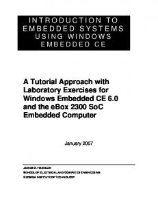
a case study. Section 8 summarizes the paper and points out our future work. 2. OVERVIEW OF HW/SW CO-DESIGN The co-design process starts with an architecture-independent description of the intended system’s functionality, the analysis of constraints and requirements on the system, and the statement of objectives. This description is independent of HW and SW, and several system representations may be utilized, e.g., finite state machines (FSMs). The system is then specified by means of a conceptual model (addressing functionality and behavior) or a programming language (e.g., VHDL, Verilog, SpecCharts, etc.) which is next compiled into an internal representation such as a data control flow description. This specification/description serves as a unified system representation that can represent HW or SW. The HW/SW functional (or architectural) partitioning is performed on this unified representation. After this step has been completed, HW, SW and the related interfaces are synthesized. Evaluation is then performed. The partitioning process is iterative, and if the evaluation does not meet the required objectives, another HW/SW partition is generated and evaluated. Figure 1 is a general view of HW/SW co-design, in which the ellipses stand for data/information entities in the system design and the squares stand for system design processes, actions or activities. The figure does not follow any specific approach; rather, it reflects a combination of several approaches presented recently in the literature. Note the partitioning stage and the integration phase common to all co-design methodologies. Codesign is still a relatively new, rapidly changing field, so that there is not one set standard for how it is to be done and many variations exist. Analysis of Constraints Requirements, and Objectives
enterprise; (2) system; (3) component; and (4) feature. The enterprise level provides a unified view of the system and its environment by capturing enterprise-related concepts. The system level determines the system being developed, distinguishing it from its environment. The environment of a system consists of information systems or human users that make use of the services provided by the system itself, as well as other systems that provide some service used by the system being developed (de Farias 2001). The component level represents the system in terms of a set of composed components. A component may be further decomposed into sub-components. A composite component is an aggregate of sub-components that, from an external point of view, is similar to a single component. If a composite component is part of a component composition, the design process of this component corresponds to the design process of an isolated system, and the environment of this system contains the other components in the composition. The feature level defines the internal structure of simple components. A component is structured using a set of related features, implemented in a feature description or a programming language. Thus, the design process of a component at the feature level corresponds to the feature-oriented design process similar to the traditional object-oriented process. The focus of this work is on the component level and the feature level. Further details on the component-level and feature-level modeling are discussed in the following sections. 4. FEATURE-BASED COMPONENT EMBEDDED SYSTEMS
MODEL
FOR
In this research, the feature model is used to provide a formal description of embedded systems and to formalize knowledge about its instantiation process. Details of the feature-based representation and modeling are discussed below.
System Specifications HW Design
SW Design
HW/SW Partitioning
Hardware Description
HW Synthesis and Configuration
Configuration Modules
Software Description
Interface Synthesis
Hardware Components
Software Generation & Parameterization
HW/SW Interfaces
Software Modules
HW/SW Integration and Cosimulation HW/SW Co-Design Integrated System System Evaluation
Design Verification
Figure 1: HW/SW co-design methodology 3. EMBEDDED SYSTEM MODELING PRINCIPLE The modeling principle adopted in this research identifies four abstraction levels for the design of an embedded system: (1)
4.1 Component-Based Modeling A component is a non-trivial, nearly independent, and replaceable part of a system that fulfills a clear function in the context of a well-defined architecture. A component conforms to and provides the physical realization of a set of interfaces. In the real world, we easily sense and touch some real hardware component systems such as Lego blocks, mechanical parts, square stones, building plants, electronic components, IC chips or hardware busses. These components generally connect through ports. A software component is generally a unit of composition with contractually specified interfaces and explicit context dependencies only. It can be deployed independently and is subject to composition by a third party. A run-time software component is a dynamically bindable package of one or more programs managed as a unit and accessed through documented interfaces that can be discovered at run-time. The widely accepted software component definition is that a software component is a part of software in binary form not compiled or rebuilt with contractually specified interfaces (i.e., defined API
2
and all assumptions in which the component can work). A component can be deployed independently or used in a plug and play mode, i.e., it can be dynamically loaded into the system or dynamically replaced. A software component must have a mechanism that makes it possible to compose/integrate the component into the system without the need of modifying and rebuilding it.
Feature 1
Feature 2
Component 1
Features
Component 1
Component 2
Component 2
Component Connectors
Component 1
Component 2
Figure 2: Component-connector model The basic concepts in the component-based modeling approach are components, connectors and systems, where a system is a configuration/assembly. Both components and connectors have connection points called ports for components and roles for connectors (Figure 2). Thus, design elements include components, connectors, ports, and roles. Components are connected to connectors by defining an attachment between the port of a component and the role of a connector. Connectors can be viewed as special communication components. One connector may connect multiple components. Components may be nested but cannot be connected directly to each other and neither can a connector to another connector. Components and connectors have attributes or properties. Properties are uninterpreted values, i.e., they do not have any semantics defined. In UML 2.0, some new concepts and major improvements have been added to support component-based modeling. UML 2.0 includes a set of constructs about components and their assembly. Component description in UML 2.0 now can include a set of ports, a set of parts, a set of connectors and a behavior. 4.2 Feature-Based Modeling 4.2.1 Feature Definition and Models A uniform feature definition that is independent of design problems can be obtained by developing an abstract and therefore generally valid “feature identification” (Fisher and Wang 1995). The following definition provided by the FEMEX
work group (FEMEX=Feature Modeling Experts) is described in more detail in (Weber 1995): 1. A feature is an information unit. 2. A feature represents a region of interest within a product. 3. A feature has a meaning that often is called the semantic of the feature. 4. A feature is described by an aggregation of properties. 5. These properties have to be formalized and represented in a product model. 6. The description of a feature contains the relevant properties including their values and their relationships (hierarchical structure and constraints). 7. A feature is defined with respect to a specific view of the product model. 8. Different views are often related to the different phases of the product life cycle. 9. A feature can also be described in terms of properties from several different views, thus relating these views to one another. 10. A feature serves to establish information units within CAxSystems that are of significance to the user. 11. A feature permits some sort of high-level communication between the user and the system and can form the basis for simulating human reasoning on the computer. The definition states that a feature can be viewed as a unit of “product” information that represents a specific “region”. The term “product” can imply a real, physical product, i.e., something that can be grasped, as well as a process. Consequently, the term “region” technologically describes a spatial or geometrical portion if an object that can be grasped or represents a time or process oriented portion of a process (Bley et al. 1996). A feature model can be used to describe the commonalities and differences between the individual hardware/software systems. A feature model gives a hierarchical structure to the features. There are four categories of features (Riebisch 2003, Riebisch et al. 2004): • Functional/behavioral features express the behavior or the way users may interact with a system. They describe both static and dynamic aspects of functionality, and may be expressed through use cases, scenarios or structure. For example, in the automotive domain, features such as “electric seat heating” and “extra daytrip mileage counter” belong to that category. • Structural features including form features and interface features express the overall form/structure of an embedded system or its HW/SW components and their relationships. Interface features express the system's conformance to a standard or a subsystem. They describe connectivity and conformance aspects as well as contained components. Examples for features from this category are the Firewire connection for an electronic camera and DDR133 RAM for
3
memory sockets of a PC. Conformity to standards and certificates are in this category as well, i.e., USB 2.0 compatible and ISO 9000 certified for a PC. Complete components or subsystems of special quality or by special vendors are added to the same category, because the handling of such features is very similar to interfaces. An example is the feature Bosch ABS device for a car, if this is valuable to a customer. • Parameter features express enumerable, environmental or nonfunctional properties. They cover all features with properties demanding quantification by value or assignment of quality, e.g., color. Examples from the automotive domain are fuel consumption, top acceleration or wheel size. • Concept features represent an additional category for structuring a feature model. They encapsulate abstract features within a hierarchical feature structure. The root of the hierarchy always represents a concept feature. Features in this category have no concrete implementation, but each of their sub-features provides one. The feature “mechanical protection” represents an example for such a feature. Within a feature model, the features are structured by relationships. Common to all methods mentioned above are hierarchical relationships between a feature and its sub-features. The hierarchical relationships control the inclusion of features into instances. If an optional feature is selected for an instance, then all mandatory sub-features have to be included as well, and optional sub-features can be included. 4.2.2 Feature Modeling with UML Feature modeling is the activity of modeling features and their interdependencies and organizing them into a feature model. It provides a model of end-user-visible features that are present in a given domain by providing a description for each feature and for each relationship among these features. Feature modeling is usually based on a two-level structure: (1) a meta-modeling level, which defines the types of features that can be used, their properties, and their mutual relationships; and (2) an entity modeling level where the feature model for the entities of interest is constructed in terms of the meta-model. Feature models require the definition of a concrete syntax and language to express them. The application feature model is seen as an instance of a feature meta-model (Beuche 2003). In this research, we use the UML-based formalisms to represent the feature meta-model (Zha and Sriram 2004). The basic ideas can be summarized as follows. A feature can have sub-features, but the connection between a feature and its subfeatures is mediated by a group. A group gathers together a set of features that are children features of some other feature. Thus, a group represents a cluster of features that are children of the same feature and that obey some constraints on their legal combination. Groups are also used to enforce local restrictions (constraints). The same feature can belong to several groups.
Both features and groups have cardinalities. The cardinality of a feature defines the number of instances of the feature that can appear in an application. The cardinality of a group defines the number of features chosen from within the group that can be instantiated in an application. Cardinalities can be expressed either as fixed values or as ranges of values. The application feature model is instantiated from the meta-model. 4.3 Feature-Based Component Modeling 4.3.1 HW/SW Components in Embedded Systems Typically, an embedded system is housed on a single microprocessor board with the software (programs) stored in some form of read-only memory, such as ROM, EPROM, or flash memory. Embedded system hardware does not use conventional I/O devices such as a keyboard, mouse or display. Instead, they interact with the outside world (environment) through their sensors and actuators. Sensors feed the input data to the system and actuators deliver the output to the external environment. Embedded system software can generally be classified into the following three categories according to the problem solving methods used (Hassani 2000): (1) numerical or data processing; (2) user interface; and (3) decision making. Numerical or data processing software is used in problems that have numerical solutions; the output response is calculated as a mathematical function of the inputs. The software is made up of a few modules that use numeric equations to produce the results. The user interface module is used for facilitating data/message passing for users. Decision-making schemes are generally applied to problems that do not have numerical solutions. Instead, they use a large number of If-THEN statements, monotonic logic, and heuristics to achieve reasonable solutions. The decision-making module typically consists of rules. Rules are sets of conditional statements with an IF-THEN structure that logically relates information contained in the condition element (IF part) to other information contained in the action element (THEN part). 4.3.2 Embedded System Component Features Hardware and software features compose hardware and software components, respectively. This means that feature configurations determine the underlying SW and HW components. As discussed above, features are classified into four categories: concept feature, function (behavioral) feature, parameter feature and structural feature (interface feature, or port). Thus, these four categories of features compose both hardware features and software features, so that the hardware feature may be specialized into HW concept feature, HW function (behavioral) feature, HW parameter feature and HW interface feature; similarly, the software feature generalizes SW concept feature, SW function (behavioral) feature, SW parameter feature and SW interface feature. Normally, interface features are also called ports, thus, we may have a SW port and a HW port, accordingly
4
in the software and hardware features. A SW port is specialized into Input Port (Requested Port), Output Port (Provided Port), In-Out Port, (Resource Port, and Configuration Constants) (Stewart et al 1993); A HW Port is specialized into Input Port (Destination Port, Requested Port), Output Port (Source Port, Provided Port), etc. 4.3.3 Embedded System Feature Interactions Embedded system connectors represent the connections between HW/SW components or subsystems in the embedded system. Connectors may be either HW/SW features or HW/SW components or HW/SW subsystems composed of HW/SW features (or HW/SW components). Embedded system connectors can be specialized into subclasses: hardware connectors, software connectors and hardware-software connectors. Hardware connectors represent connections between hardware components or subsystems in the embedded system. Software connectors represent connections between software components or subsystems in the embedded system. Hardware-software connectors represent connections between hardware and software components or subsystems in the embedded system. Differing from interface features of HW/SW components, interface features of HW/SW/HW-SW connectors are sometimes called roles. HW Port HW Component
HW Interface Feature
SW Component
SW Interface Feature
HW Component
HW Interface Feature
HW Interface Feature
HW Component
SW Interface Feature
SW Component
SW Interface Feature
SW Component
SW Port
HW Port SW Port
Figure 3: Feature interaction scenario in an embedded system The scenario of feature interactions in an embedded system can be described as in Figure 3. We propose to model feature (port) interactions so as to comply with the component-connector model based on UML 2.0. We also model feature interactions with feature-solution (FS) graphs which connect features with solution fragments (Bruin and Vliet 2001). The Form of the artifact can be viewed as the proposed design solution for the design problem specified by the function (Fenves 2001, Fenves et al. 2005). Thus, the feature-solution graph is equivalent to the feature-form graph. The feature-form graph serves two purposes: (1) to pinpoint feature interactions; and (2) to guide an iterative architecture development and evaluation process. The feature space consisting of feature models describes the desired properties of the system as expressed by the user. The form/solution space contains the internal system decomposition in the form of a reference architecture composed of components. In addition, the form space may also contain general applicable solutions that can be selected to meet certain non-functional requirements. Further details will be discussed in Section 6.
5. UML REPRESENTATION FOR EMBEDDED SYSTEM FEATURE MODEL The Open Embedded System Model (OESM) has been developed at NIST to provide a standard representation and exchange protocol for embedded systems and system-level design, simulation, and testing information (Zha, Fenves and Sriram 2005). In this section, we only discuss in detail the embedded system feature model in OESM, i.e., the Open Embedded System Feature Model (OESFM), related to models of embedded system artifacts, embedded system components, embedded system features, and embedded system configuration/assembly. We use UML notation and diagrams to explain the embedded system feature model. 5.1 Extensions of the NIST Core Product Model to Embedded Systems NIST research efforts toward the development of the basic foundations for the next generation CAD systems lead to the NIST Core Product Model (CPM) (Fenves 2001, Fenves et al. 2005). However, CPM currently focuses mainly on the physical artifact (e.g., motor, airplane), especially for electro-mechanical products or assemblies. There is a need to make some modifications/extensions for it to be used for an informational artifact (e.g., software, organizations, business processes, plans and schedules). Consequently, CPM needs some modifications/extensions when applied for modeling embedded systems. The modification/extension of the CPM includes expanding semantically the definitions of some concepts and/or extending existing classes or adding new classes. For more information on the CPM, please refer to (Fenves 2001, Fenves et al. 2005). In the OESFM extension of NIST-CPM, ESArtifact refers to an embedded system or one of its hardware/software (HW/SW) components. ESArtifact is extended from the NISTCPM Artifact class and specialized into two classes: HWArtifact and SWArtifact. HWArtifact refers to a hardware system/component in an embedded system, which is an aggregation of HWFunction, HWForm and HWBehavior. HWFunction represents what the artifact is supposed to do; HWForm represents the proposed design solution for the design problem specified by the hardware function; and HWBehavior represents how the hardware artifact realizes its function. HWForm itself is the aggregation of Geometry, the spatial description of the artifact, and Material, the internal composition of the hardware artifact. HWFeature represents any information in the HWArtifact that is an aggregation of HWFunction and HWForm. SWArtifact refers to a software system in the embedded system or one of its software components, i.e., which is an aggregation of SWFunction, SWForm and SWBehavior. SWFunction represents what the software artifact is supposed to do; SWForm represents the proposed solution for the design problem specified by the
5
software function; SWBehavior represents how the software artifact implements its function. SWForm itself is the aggregation of Architecture, the structural description of the software artifact, and Code, the internal composition of the software artifact. The class Code is also specialized into two subclasses: SourceCode and BinaryCode. SWFeature Specification (f rom NIST Core Model+)
DesignSpecification
SystemSpecification
(f rom DesignSpecif ication)
(f rom Sy stemSpecif ication)
SystemPartitioning
ESArtifact Platform
Artifact
(f rom Sy stemPartitioning)
(f rom ESPlatf orm)
(f rom NIST Core Model+)
0..* +sub_systems
+sub_systems_of View
ESArtifact
EmbeddedSystem
(f rom View)
(f rom ESArtif act)
+defined_EmbeddedSystem +configuration_relationship
+connector_of
+component_of
CompositionAssociation
HWArtifact
SWArtifact
(f rom CompositionAssociation)
(f rom HWArtif act)
(f rom SWArtif act)
+realizes +realized by ESConnector (f rom ESConnector)
1..* +connectors 0..*
+components ESFeature (f rom ESFeature)
+features
+feature_of
ESComponent
represents any information in the SWArtifact that is an aggregation of SWFunction and SWForm. All the above entities have their own independent containment (“part-of”) hierarchies. For more details, please refer to (Zha, Fenves and Sriram 2005). The class ESComponent represents embedded system component, which is a composition of ESFunctionFeature, ESConceptFeature, ESParameterFeature and ESStructuralFeature. It is specialized into HWComponent and SWComponent. Thus, HWComponent is an aggregation of HWFunctionFeature, HWConceptFeature, HWParameterFeature and HWStructural Feature; SWComponent is an aggregation of SWFunctionFeature, SWConceptFeature, SWParameterFeature and SWStructuralFeature. HWInterfaceFeature is a specialization of HWStructuralFeature; SWInterfaceFeature is a specialization of SWStructuralFeature.
(f rom ESComponent)
1..*
HWConceptFeature
ManufacturingFeature (from M anufacturingFeature)
Figure 4: Main schema of the Open Embedded System Feature Model
HWParameterFeature AnalysisFeature (from Analysi sFeature)
HWFunctionFeature HWFeature
5.2 Representation for the Embedded System Feature Model
DesignFeature
HWStructuralFeature
Figure 4 shows the main schema of the Open Embedded System Feature Model (OESFM). The main embedded system model schema incorporates information about design specification, partitioning, embedded system specification, and component composition and configuration/assembly relationships. The model incorporates information about component composition (part-of) and assembly/configuration relationship. The component composition of an embedded system is modeled using this part-of relationship. An embedded system represented by the EmbeddedSystem class is decomposed into hardware/software (HW/SW) subsystems and components, and connectors connecting theses subsystems and components. Each embedded system component represented as ESComponent class in the ESComponent package, whether a HW/SW subsystem or component, is made up of one or more HW/SW features, represented in the model by ESFeature class in the ESFeature package. The EmbeddedSystem and ESComponent classes are subclasses of the ESArtifact class (extended from NIST-CPM Artifact class, see above). ESFeature is a subclass extended from the NIST-CPM Feature class. The composition (configuration/assembly) relationship is represented by a class named CompositionAssociation. Components or subsystems in the embedded system are connected by connectors represented by ESConnector class in the ESConnector package. Connectors may be either features or components or subsystems composed by features or components. We only summarize some of them below.
(from DesignFeature)
HWInterfaceFeature HWPort
AssemblyFeature (from AssemblyFeature)
HWConnector
HWSWConnector
ConnectionFeature
HandlingFeature
(from HWConnector)
(from HWSWConnector)
(from AssemblyFeature)
(from AssemblyFeature)
(a) Hardware feature HWConnector
HWSWConnector
(from HWConnector)
(from HWSWConnector)
HWInterfaceFeature (from HWFeature)
ESConnector (from ESConnector)
Port (from Port)
InterfaceFeature
HWPort
CompositionAssociation (from Composi tionAssoci ation)
(from HWFeature)
SWInterfaceFeature (from SWFeature)
InterfaceFeature Association
SWPort (from SWFeature)
SWConnector (from SWConnector)
Port
InterfaceFeatureAssociationRepresentation
ES_ArtifactAssociation (from ES_ArtifactAssociation)
(b) Interface feature
6
ESInterfaceFeatureAssociationRepresentation. The diagram also shows that the ESArtifact Association is the aggregation of ESInterfaceFeatureAssociation. The class ESConnector represents the connections between components or subsystems in the embedded system. Connectors may be either features or components or subsystems composed of features or components. ESConnector is specialized into subclasses: HWConnector, SWConnector and HWSWConnector. The HWConnector represents the connections between hardware components or subsystems in the embedded system. SWConnector represents the connections between software components or subsystems in the embedded system. HWSWConnector represents the connections between hardware and software components or subsystems in the embedded system.
SWParameterFeature
SWFunctionFeature SWFeature SWConceptFeature SWStructuralFeature
SWConnector (from SWConnector)
SWInterfaceFeature HWSWConnector (from HWSWConnector)
SWPort
(c) Software feature FunctionFeature Feature (from NIST Core Model+)
ParamterFeature
6. FEATURE-BASED HW/SW CO-DESIGN ConceptFeature
ESFeature
CompositeFeature
StructuralFeature SWFeature
HWFeature
(from SWFeature)
(from HWFeature)
InterfaceFeature (from InterfaceFeature)
Port (from Port)
(d) Embedded system feature Figure 5: Class diagram of embedded system features (HW features, SW features, interface features) The class ESFeature (Figure 5) is a sub-class of the Feature class defined in NIST-CPM. It inherits the function and form information from Feature. ESFeature is specialized into the following subclasses: ESFunctionFeature, ESConceptFeature, ESParameterFeature, and ESInterfaceFeature. ESFeature has three subclasses: HWFeature, SWFeature, and CompositeFeature. CompositeFeature represents a composite feature that can be decomposed into multiple simple features. SWFeature is specialized into SWFunctionFeature, SWCeonceptFeature, SWParameterFeature, and SWInterfaceFeature. SWInterfaceFeature is specialized into SWPort. SWPort is specialized into InputPort, OutputPort, and InOutPort. HWFeature is specialized into HWFunctionFeature, HWCeonceptFeature, HWParameterFeature, and HWInterfaceFeature. HWInterfaceFeature is specialized into HWPort. HardwarePort is specialized into InputPort and OutputPort. The class ESInterfaceFeature is specialized into two subclasses: HWInterfaceFeature and SWInterfaceFeature. The class ESInterfaceFeatureAssociation refers to the composition/assembly relationship between one or more embedded system interface features. This relationship is represented by the class
6.1 Feature-Component Mapping The feature-oriented reuse method (FORM) is an extension of feature-oriented design and analysis (FODA) that includes form (architecture for SW) design and object-oriented component development. The method assists in the development of reusable and adaptable artifacts from product features (Kang et al. 1998, 2002). FORM begins with feature modeling, where the resulting feature model serves as the basis for reusable and adaptable artifacts. Figure 6a illustrates the development activities in FORM. During the form (architecture) design activity, features are allocated to architectural components and the dependencies between them are specified. The functional architecture, constituting the architectural components, is refined into process and deployment architectures, which are used during the component design process. Figure 7 illustrates how the feature configuration determines the underlying SW and HW component configuration. Feature Model
Feature Modeling Feature Model
Architecture Design
Feature Architecture
Functional Architecture
Candidate Object Identification
Feature Model
Architecture Refinement Process Architecture
Design Object Modeling
Design Object Model
Deployment Architecture
Component Design
(a) Activities in FORM (Kang et al. 2002) Feature F Usage scenario Design & execution trace Required components (C1,…,Cn) (F,C1),…,(F,Cn) Concept analysis Feature-component correspondence
(b) A mapping scenario
7
Copyright © XXXX
Figure 6: Feature-component mapping Feature Model
Form Architecture
SW
F11 F0
F12
F122
F13 HW Feature configuration determines the underlying SW and HW components
(Fr) space contains the requirements, whereas the Form (Fm) space contains forms/solutions addressing these requirements. Features as well as forms/solutions are decomposed in AND(EX)OR decomposition trees. An AND decomposition of a node in either the feature or the form space means that all its constituents must be available, an OR requires an arbitrary (>=0) number of constituents, and an EXOR requires precisely one constituent. The key idea is that a feature in the Feature space may select a form in the Form space as defined by directed selection links between nodes (indicated by a solid line in Figure 8). It is also possible to explicitly rule out a particular form (solution). This is done by connecting a feature to a form with a negative selection link (indicated by a dashed line). Considered as an example is a Client-Server system in which a client component requests a server component to perform one of its duties (Bruin and Vliet 2001). A FrFm-graph for the Client-Server system is shown in Figure 8.
Figure 7: Feature configuration determines the underlying SW and HW components The implementation of the technique described here is based on the design and execution traces generated by a profile for different usage scenarios (Eisenbarth 2001), as shown in Figure 6b. One scenario represents the invocation of one single feature or a set of features and yields all artifacts/sub-artifacts (e.g., sub-programs as sub-software artifacts) executed for these features. These artifacts/sub-artifacts (sub-programs) identify the components (or are themselves considered components) required for certain features. The required components for all scenarios and the set of features are then subject to concept analysis. Concept analysis gives information on relationships between features and required components. 6.2 Component Generation In this section, we propose a systematic technique that generates system components from functional as well as non-functional requirements. The generation technique is based on two pillars: 1) Feature-form (FrFm) graphs. The FrFm-graph captures architectural knowledge in the form of desired features (e.g., functional and non-functional requirements) and forms representing solutions that realize these features (e.g., architectural and design patterns). 2) Top-down component composition. The steps in this process are: i) derivation of a reference architecture that meets the set of functional requirements; ii) application of known design solutions/forms focusing on non-functional requirements as codified in the FrFm-graph. Typically, the generation technique requires several iterations. These iterations might also involve backtracking steps because we usually have to deal with conflicting requirements. There are two spaces, namely the feature space and the form/solution space, recognized in the FrFm-graph. The Feature
Feature Space
Form Space
Figure 8: Feature-Form graph for the Client-Server system 6.3 Architectural Form Modeling Form modeling, also referred as architectural modeling, is the framework for constructing an application. An architectural model is the high-level design solution (form) of the design/application. It defines the basic building blocks, including basic partitions and interconnections necessary for constructing the design/application. The architectural form model serves as a frame for organizing architectural elements. Two of the fundamental works on architectural form modeling are the “4+1 view” model (Kruchten et al. 1995) and the “4 views” architectural model (Hofmeister et al. 2000). The “4+1 View” model suggests organizing the architectural descriptions in five different categories called views: logical view, process view, physical view and development view. The fifth view, namely the user’s view, contains scenarios and use cases and is used for defining requirements and for validating the previous four. The model separates static and dynamic aspects of the software architecture. The solutions to functional requirements are concerned mainly in the logical view. The process view focuses on dynamic aspects of the model and also describing real-time (runtime) behavior. The physical view shows the solutions primarily to non-functional requirements and maps software to hardware. The development view focuses on the actual software module organization and on the software development environment. It also focuses on requirements
8
Copyright © XXXX
related to the ease of development, software management, reuse or commonality, and to the constraints imposed by the toolset or the programming language. The “4+1 views” architectural model has become very popular during the last decade, especially for new development. The “4 views” architectural model also proposes separate descriptions of the different architectural parts. The four views presented are: conceptual view, module view, execution view and code view. The conceptual view describes the system in terms of its major design elements and the relations between them. The module view presents the decomposition of the system and the partitioning of modules into layers. The code view is the organization of the source code into object code, libraries and binaries, then in turn into versions files and directories. The mapping from software to hardware and distribution of the software components is the task of the execution view. Both models have their advantages and disadvantages with the “4 views” architectural model addressing the case of “mixed” software systems - building on both object and non-object oriented technology - in a more efficient way. “Mixed” software systems are common in software legacy systems. For this reason, in practice, we may need to combine these two architectural models for embedded systems, in which the “4 views” model is especially used as the basic architectural model of embedded software.
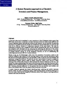
HW/SW components. Based on these features, HMCS can be designed using the prototype system developed for featurebased embedded system virtual prototyping. This prototype system incorporates the feature-modeling tool, CaptainFeature (2004), so that HW/SW co-design can be implemented.
Speed
Hydraulic System
Display
AVR-Microcomputer Controller
Pressure
Temperature PC
ABS
USB
RS232
Modem/Internet PC-Connection
UDP/SLIP/TCP/IP or special protocol over USB/RS232/Modem/Internet
Figure 9: The hydraulic measure and control system Features/Feature Configurations
HW/SW Form Architecture
SW
7. CASE STUDY In this section, we use a simple hydraulic measurement and control system (HMCS) as a case study to illustrate the featurebased HW/SW co-design approach discussed above. This example is inspired by a weather station system (Beuche 2003) and described in (Zha and Sriram 2004). The goal is to design a complete hydraulic measurement and control station for testing/diagnosing car antilock braking systems (ABS) based on a small experimental microcontroller ATMEL ATMEGA103. The microcontroller board is equipped with several sensors (pressure, temperature, speed) and has an LCD display, a serial controller, a USB controller, and Modem/Internet controller for output and input purposes. Figure 9 shows the schematic of the hydraulic measurement and control system. Table 1 gives a partial list of the components features. Table 2 provides a component list of the system. The feature-form mapping for HW/SW co-design is shown in Figure 10, including feature configuration, feature diagram and its UML representation,
ID
1
Component name
Hydraulic system
HW Hydraulic Measurement and Control System
LCD Display
Hydraulic System
ABS
AVR-Micro computer
Speed Sensor
Figure 10: Feature-form mapping for HW/SW co-design
Table 1: Partial component feature list of the system Feature descriptions Concept Functional/Behavioral Structural feature feature feature (interface) Actuator, Speed, Input port, power supply pressure, output port temperature
9
Parameter feature Cost $, weight, size
Copyright © XXXX
2
Pump
Power supply
3
Valve
Flow control
4
Cylinder
Actuator, force transmission
5
Microcomputer controller
Processor and controller
6
Speed sensor
Input (speed)
Resolutions
7
Pressure sensor
Input (pressure)
Resolutions
8
Input (temperature)
Resolutions
9
Temperature sensor LCD Display
Resolutions
10
RS232 –Serial
11
RS 232 driver
12
USB protocol
13
Modem/Internet protocol
Output (formatted and unformatted) Output(formatted, UDP, unformatted) Output (interrupt operation, change parameters, SCC, SCI, UART) Output (formatted and unformatted) Output (formatted, TCP/IP, unformatted)
…
…
…
Power, pressure, speed, flow, etc. Viscosity, pressure, ambient temperature, max flow, etc. Load (transmission force limit), etc. Memory size, etc
Size, running speed, etc Transmission rate, etc. Connection speed, Transmission rate, etc. …
Input port, output port
Cost $, weight, size
Input port, output port
Cost $, weight, size
Input port, output port
Cost $, weight, size
64 Pin TQFP (Input port, output port) Input port, output port Input port, output port Input port, output port Input port
Cost $, size
Input port, output port
File Size
…
…
Cost $, size Cost $, size Cost $, size Cost $, size
Table 2: Component list of the system ID 1 2 3 4 5 6
Component Name Micro controller board Speed sensor Pressure sensor Temperature sensor LCD display PC computer
7 8
Hydraulic system Antilock braking system (ABS) Modem/Network card Interface cable
9 10
Functional Description Storage and memory (4KB RAM, 8kB flash memory) Measure speed Measure pressure Measure temperature Display results Central processing and control, Data terminal equipment (DTE) Actuator of ABS (pump, valve) Anti-lock the braking system of a car
HW (mechanical) HW (mechanical)
Data communicating equipment (DCE) Connect
HW (electronic) HW (electronic)
10
HW/SW HW (electronic) HW (mechanical) HW (mechanical) HW (mechanical) HW(electronic) HW (electronic)
Copyright © XXXX
11 12 13 14 15
Modem protocol & Internet protocol (TCP/IP) USB protocol (driver) RS232 protocol (driver) LCD output driver Pressure sensor driver
16
Speed sensor driver
17
Temperature sensor driver
18
Diagnosis system
Connect/communicate, data transmission and exchange Connect, data transmission and exchange Connect, data transmission and exchange Determine how PC will communicate with an LCD Determine how microcomputer communicates with a pressure sensor Determine how microcomputer communicates with a speed sensor Determine how microcomputer communicates with a temperature sensor Diagnose the fault and provide maintenance suggestions
8. SUMMARY AND CONCLUSIONS In this paper, we describe a feature-based modeling approach to co-design of hardware and software in embedded systems. The approach first defines an extension to the NIST Core Product Model and then provides an object-oriented UML representation for the embedded system feature model (OESFM), including models of embedded system artifacts, components, features, and HW/SW configuration/assembly. This model can provide a feature-based HW/SW component codesign framework and allow the designer to develop a virtual embedded system prototype through assembling virtual components. A case study example is discussed to illustrate the HW/SW co-design process in the embedded system model. Currently, we are developing feature ontology for HW/SW codesign based on the OESFM. Our near future work is expected to make the model/approach harmonized with other models/approaches and interoperate with various EDA systems and also explore the possibilities of integrating it with virtual prototyping systems based on a component agent technology. Disclaimer No approval or endorsement of any commercial product, service or company by the National Institute of Standards and Technology is intended or implied. REFERENCES Aßmann, U., Schmidt, R. (1997), Towards a model for composed extensible components, Workshop Foundations of ComponentBased Systems, Proceedings, Zurich, Switzerland Beuche, D., Papajewski, Holger, Schroder-Preikschat, W. (2004), Variability management with feature models, Science of Computer Programming, Elsevier Publishers, to appear Beuche, D. (2001), Feature based composition of an embedded operating system family, Proceedings of ECOOP 2001 Workshop #08 Feature Interaction in Composed System, In Association with the 15th European Conference on Object-Oriented Programming, Budapest, Hungary
SW (Data processing) SW (Data processing) SW (Data processing) SW (Data processing) SW (Data processing) SW (Data processing) SW (Data processing) SW (Decision-making)
Beuche, D. (2003), Composition and Construction of Embedded Software Families, PhD Dissertation, der Otto-von-GuerickeUniversität, Magdeburg, Germany Berg, K. Müller, J., Bishop, J. and van Zyl, J. (2004), The use of feature modeling in component evolution, Technical Report, http://polelo.cs.up.ac.za/publications.htm Bley, H., Seel, U., and Gunther, K.G. (1996),Solving technical problems in assembly system’s design, Annals of the CIRP, Vol.45/1, pp.11-15, 1996 Bruin, H. and Vliet, H. (2001), Feature and feature interaction modeling with feature-solution graphs, 2001 Captain Feature (2004): Project page. https://sourceforge.net/projects/ captainfeature, Last accessed in March 2004. de Farias, C. R Guareis., Ferreira Pires, L., van Sinderen, M. and Quartel, D., A combined component-based approach for the design of distributed software systems, wwwhome.cs.utwente.nl/~pires/publications/ftdcs2001.pdf Deursen, A. and Klint, P. (2001), Domain-Specific Language Design Requires Feature Descriptions, CWI Report, SEN-R0126, ISSN 1386-369X Eggermont, L. D.J. (ed.) (2002), Embedded Systems Roadmap 2002, Vision on Technology for the Future of PROGRESS, 30 March Eisenbarth, T., Koschke, R. and Simon, D. (2001), Feature-driven program understanding using concept analysis of execution traces, Proceedings of the International Workshop on Program Comprehension (IWPC’01), May 12-13, Toronto, Canada Fenves, S. (2001), A Core Product Model for Representing Design Information, NISTIR 6736, NIST, Gaithersburg, MD. Fenves, S., Foufou, S., Bock, C., Bouilon, N., Sriram, R.D., (2005), CPM 2: A Revised Core Product Model for Representing Design Information, NISTIR 7185, NIST, Gaithersburg, MD. Fisher, A. and Wang, K.K.(1995), An interaction mechanism for 3D object-oriented feature-based models in interactive design and simulation, CIRP Annals, Vol.44/1. pp.101-104 Gurp, J., and Bosch, J., Managing variability in software product lines, Landelijk Architectuur Congres, Amsterdam 2000 Hassani, M., A Component-based Methodology for Real-time Decision-making Embedded Systems, PhD Dissertation, University of Maryland, 2000 Crnkovic, I. and Larsson, M. (2001), Component-based software engineering – new paradigm of software development, Invited Talk & Invited Report, Proceedings of MIPRO 2001, Opatija, Croatia
11
Copyright © XXXX
Hofmeister, C., Nord, R. and Soni, D. (2000), Applied Software Architecture. Addison Wesley. Jansen, A., Smedinga, R., Gurp, J. and Bosch, J., (2003), Featurebased product derivation, http://www.cs.rug.nl/~rein/ publications/ FeatureComposition.pdf Kang, K., Kim, S., Lee, J., Kim, K., Shin, E. and Huh, M. (1998), FORM: A feature-oriented reuse method with domain-specific reference architectures, Annals of Software Engineering, Vol.5, J. C. Baltzer, AG Science Publishers, Red Bank, NJ, USA, pp. 143168. Kang, K. C., Lee, J. and Lee, K. (2002), Feature Oriented Product Line Software Engineering: Principles and Guidelines, Chapter 2, Domain Oriented Systems Development: Perspectives and Practices, Taylor & Francis, UK Kruchten, P. (1995), The 4+1 View Model of Architecture, IEEE Software, 12(6): 42-50 Pashov, I., and Riebisch, M. (2004), Using feature modeling for program comprehension and software architecture recovery, Proceedings of 11th Annual IEEE International Conference and Workshop on the Engineering of Computer Based Systems (ECBS2004), Brno, Czech Republic, pp. 406-117 Rozenblit, J. and K. Buchenrieder (editors) (1994), Codesign Computer -Aided Software/Hardware Engineering, IEEE Press, Piscataway, NJ Rastofer, U. (2002), Modeling with components– towards a unified component meta model, Proceedings of ECOOP 2002 Workshop #12 Model-based Software Reuse, Malaga, Spain Riebisch, M. (2003), Towards a more precise definition of feature models, Modeling Variability for Object-Oriented Product Lines, M. Riebisch, J. O. Coplien, D, Streitferdt (Eds.), Book On Demand Publ. Co., Norderstedt, pp. 64-76. Riebisch, M., Streitferdt, D. and Pashov, I. (2004), Modeling variability for object-oriented product lines, in Buschmann, Frank; Buchmann, Alejandro P.; Cilia, Mariano (Eds.): Object-Oriented Technology, ECOOP 2003 Workshop Reader, Springer, Lecture Notes in Computer Science, Vol. 3013, pp. 165 - 178. Stewart, D.B., Volpe, R.A, and Khosla, P.K. (1993), Integration of real-time software modules for recogfiguration sensor-based control systems, Proceedings of International Symposium on Intelligent Robotics (ISIR’93), Bangalore, India Tierney, P.J. and Ajila, S. A. (2002), FOOM - Feature-based object oriented modeling: implementation of a process to extract and extend software product line architecture, PDSTD’02 – SCI2002 / ISAS2002, July 14 – 18, 2002, Orlando, USA. Weber, C.H. (1995), Feature-definition, FEMEX Working Group I, Feature Definition and Classification, Chair of Engineering Design /CAD, University of the Saarland, Germany Zha, X. F. and Sriram, R.D. (2004), Feature-based component model for design of embedded system, in Intelligent Systems in Design and Manufacturing V, edited by B. Gopalakrishnan, Proceedings of SPIE Vol.5605 (SPIE, Bellingham, WA, 2004), pp. 226-237 Zha, X.F., Fenves, S.J. and Sriram, R.D. (2005), Object oriented representation for embedded system using UML, Working Paper, National Institute of Standards and Technology, USA
12
Copyright ©