Delft University of Technology Software Engineering Research Group Technical Report Series
Applying a Model-Based Approach for Embedded System Development Christian Bunse, Hans-Gerhard Gross, and Christian Peper
Report TUD-SERG-2007-020
SERG
TUD-SERG-2007-020 Published, produced and distributed by: Software Engineering Research Group Department of Software Technology Faculty of Electrical Engineering, Mathematics and Computer Science Delft University of Technology Mekelweg 4 2628 CD Delft The Netherlands ISSN 1872-5392 Software Engineering Research Group Technical Reports: http://www.se.ewi.tudelft.nl/techreports/ For more information about the Software Engineering Research Group: http://www.se.ewi.tudelft.nl/
c copyright 2007, Software Engineering Research Group, Department of Software Technology, Faculty
of Electrical Engineering, Mathematics and Computer Science, Delft University of Technology. All rights reserved. No part of this series may be reproduced in any form or by any means without prior written permission of the publisher.
SERG
Bunse, Gross, Peper – Applying a Model-Based Approach for Embedded System Development
Applying a Model-based Approach for Embedded System Development Christian Bunse
Hans-Gerhard Gross
Christian Peper
International University in Germany Campus 2 / School of IT 76646 Bruchsal, Germany Email:
[email protected]
Software Engineering Research Group Delft University of Technology Mekelweg 4, 2628 CD Delft, The Netherlands Email:
[email protected]
Fraunhofer Institute Experimental Software Engineering Fraunhofer-Platz 1, 67663 Kaiserslautern, Germany Email:
[email protected]
Abstract—Model-based and component-oriented software development approaches are slowly superseding traditional ways of developing embedded systems. For investigating to which extent model-based development is feasible for embedded system development, we conducted a case study in which a small embedded system is developed using the MARMOT approach. In order to evaluate the degree of reuse that might be achieved, the components of the case study are used in the context of different small projects. Several aspects of reuse, application size, ease of adaptation, and development effort are quantified. This analysis reveals that model-based and component-oriented development performs well for small embedded systems, and it leads to the conclusion that model-driven/component-based development of embedded systems enables adaptable applications with higherthan-normal reuse rate.
I. I NTRODUCTION The main motivation for applying model-driven and component-based engineering techniques is that new applications can be created with much less effort than in traditional approaches, simply by assembling existing parts. The principles of model-driven and component-based development are successfully applied in hardware manufacturing (e.g., production lines in the automotive industry). However, embedded software systems are still afar from rapid application assembly with components. Many embedded system projects are targeted at small 8 or 16 bit processors with limited resources, whereby the complexity of these systems is continuously increasing. This leads engineers to applying informal but structured development techniques including the application of object and component technologies, and the UML [28] as a unifying specification notation. The underlying hypothesis is that applying such techniques will help control the complexity of embedded systems, and improve maintainability, adaptability and portability, as well as time-to-market [12]. Component-based development methods, technologies, and tools have evolved well in the information systems domain. However, engineers working in the embedded systems domain do not readily exploit the effects of component technology and modeling for an apparent reason: We believe, the disciplines involved, mechanical-, electronic-, and software engineering, are not in sync, a fact which cannot be attributed to any one of these fields alone. Engineers are struggling hard to master the TUD-SERG-2007-020
pitfalls of modern, complex embedded systems, and often they only approach the problems from their individual perspectives. What is really lacking is a vehicle to transport the recent advances in software engineering and component technologies into the embedded world in a way that engineers of the three disciplines can actually communicate and understand each other. This paper introduces the MARMOT development method [4] for mastering multi-disciplinary (involving mechanical and software engineering and electronics) embedded systems development. It provides templates, models and guidelines for the products describing a (software) system, and how these artifacts are built up throughout the development process. We introduce a case study in which we apply MARMOT to the development, adaptation and reuse of components in the context of a control system for a car’s exterior mirror. We validated the expected benefits concerning reuse, time-tomarket, adaptability, etc., according to several aspects such as number and size of models, amount of reuse, defect numbers, etc. Section II gives an overview on related work. Sections III and IV describe MARMOT in detail including product and process model. Section V presents the case study in detail including example UML models, and Section VI presents the evaluation of the case study and describes results obtained. Finally, Section VII presents a brief summary, conclusions drawn, and the hypotheses for future research. II. R ELATED W ORK Growing complexity and short release cycles of embedded systems stimulated the transfer of model-driven development techniques to the domain of embedded software systems. There are two research routes: Formal modeling languages for embedded system design, and non-formal approaches using standard notations such as UML. Initially, formal languages such as Z [19], functional decomposition [26], or state-based notations [11] were used, but these approaches lack reuse mechanisms on higher levels of abstraction. Newer developments such as MATLAB [24] or MODELICA [9] provide tool and (additional) methodological support, but lack effective reuse strategies and adaptation mechanisms. Recently, the 1
Composition
ati
lid
Va
on
re
a rdw
Ha
ry na /Bi rce de u So Co
Decomposition
l
de Mo
Concretization
od
b Em
Genericity
Composition
SERG
Bunse, Gross, Peper – Applying a Model-Based Approach for Embedded System Development
t
en
im
Abstraction
Specialization
Decomposition
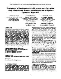
(a) Component meta model.
(b) Development dimensions.
Fig. 1: MARMOT’s product and process models.
Unified Modeling Language (UML) [28] was adapted for modeling embedded and real-time systems, but it still lacks precise semantics, and guidelines about its usage. OMEGA [13], HIDOORS [32], or FLEXICON [22], or the work presented in [7], [8], [20], [23], [30] define development methods for real-time and embedded systems using the UML. Although a step in the right direction, they often do not use the enhanced features of UML 2.0, nor do they address complexity and reuse issues. Another problem is the inadequate support for mapping UML (2.0) models to code [15]. Developers follow traditional approaches, and a complete transition to object- or component technology is prevented by the required time and space efficiency of the product, or due to standards to be followed (e.g., DO-178B in the civil aviation domain). Embedded system development would benefit from the advantages of model-driven development (MDD) [15] if the technologies could be integrated into existing development processes (i.e., keep C as target language). Most approaches and tools map models to sophisticated languages (e.g., Java, resulting in runtime performance, memory, or timing problems [15]), or use straightforward mapping strategies (UML to C) that neglect concepts such as inheritance or dynamic binding.
some reusable components, and eventually build a component repository. But they are unsure about the return on investment gained by initial component development plus reuse for a real system, and the impact of the acquired technologies on quality and time-to-market. This is the motivation for performing this case study and assessing the benefits of these techniques. A. Research Questions Our research questions focus on two sets of properties of MDD in the context of component-oriented development. The first set of questions (Q1-Q4) will lead to an understanding of basic and/or general properties of a methodological approach to embedded system development: •
•
•
III. R ESEARCH A PPROACH By applying MDD and component-based development (CBD) methods, engineers expect an increase of model or component reuse, and, thus, shorter time-to-market, improved adaptability, and higher quality. However, introducing MDD and CBD principles in an organization is generally a slow and incremental procedure [21]. An organization will start with 2
•
Q1: Which process was used to develop the system? The answer to this question will give a brief qualitative description of the method we used for developing the initial exterior mirror system (MARMOT, RUP, Agile). Q2: Which types of diagrams have been used? Are all 13 UML diagram types required, or is there a specific subset sufficient for a domain? Q3: How were models transferred to source code? Developers typically follow the traditional procedural paradigm (i.e., C) that impedes the transformation of UML concepts into C [15]. Q4: How was reuse applied and organized? Reuse is central to MDD with respect to quality, time-to-market, and effort, but reuse must be built into the process, it does not come as a by-product (i.e., components have to be developed for reuse). TUD-SERG-2007-020
Bunse, Gross, Peper – Applying a Model-Based Approach for Embedded System Development SERG The second set of questions (Q5-Q9) deals with the resulting product of the applied MDD/CBD approach. The developed systems are examined from a customer’s point of view, with respect to code size, defect density of the released code, and time-to-market. • Q5: What is the model-size of the systems? MDD is often believed to create a large overhead of models, even for small projects. Model-Size is calculated by using standard metrics as defined in [18]. • Q6: What is the defect density of the code? Defect density is computed per one hundred lines of code. • Q7: How long did it take to develop the systems and how is this effort distributed over the requirements, design, implementation, and test phases? Effort saving is one promise of MDD and CBD [31], though, it does not occur Fig. 2: Exterior mirror control system. immediately (i.e., in the first project), but in follow-up projects. Effort is measured for all development phases describes the number of hardware and software comto identify where savings are realized. ponents within the system. NCM is used to denote the • Q8: What is the size of the resulting systems? MDD for number of software components. These metrics are comembedded systems will only be successful if the resulting parable to the traditional LOC or McCabe’s cyclomatic code size, obtained from the models, is small. complexity (MVG) for estimating the size and nesting of • Q9: How much reuse did take place? Reuse is central a system’s program code [16]. for MDD and CBD and it must be seen as an upfront • Code-size measured in normalized LOC (i.e., without investment paying off in many projects. Reuse must be comment and blank lines). examined between projects and not within a project. • System-size is measured in KBytes of the hex-file to be B. Research Procedure flashed to the controller. All systems were compiled using The assumption is that by using a systematic method (i.e., the GCC’s space optimization facilities. MARMOT), we can obtain efficient reuse, and shorter time• The amount of reuse is described as the proportion of to-market. However, such claims need to be evaluated. The the system which can be reused without any changes or benefits of MDD and CBD are only realized in follow-up with small adaptations (i.e., configuration but no model projects, so that we developed an initial mirror control system change). Measures are taken at the model and the code as basis for further application engineering. Students of the level and are normalized using the system size (model, Department of Computer Science at the Technical University LOC). of Kaiserslautern used the initial system documentation and • Defect density is measured in defects per 100 LOC MARMOT as method in the context of different (small) (defects collected via inspection and testing activities) system development projects. The students were taught basic • Development effort and its distribution over development software engineering principles, object-oriented development phases are measured as development time. Since all techniques, and UML. All students had sufficient knowledge of projects were quite small, development hours were used, developing micro-controller-based applications through partcoming from daily effort sheets. time employment at local companies. Students knew that IV. OVERVIEW OF MARMOT data would be collected and analyzed. They were unaware of the concrete nature of questions/hypotheses being tested. Reuse can be seen as a major driving force in hardware The student projects were organized according to typical reuse and software development. Reuse is pushed forward mainly situations in component-based development, and a number of by the growing complexity of systems. This section introduces measurements to answer the research questions of the previous the MARMOT method that facilitates reuse in embedded sub-section were performed. The measures are: systems development. MARMOT is an extension to the KobrA • Model-size measured using the absolute and relative method [2], a component-based development framework for size measures proposed in [18]. Relative size measures, information systems, and it adds concepts addressing the defined as ratios of absolute measures, are used to address specific requirements of developing embedded systems. UMLs multi-diagram structure as well as to deal with Composition is a key activity in component-based developcompleteness issues [18]. The absolute size measures ment with MARMOT. A system is viewed as a hierarchy of (i.e., metrics that measure numbers of elements or LOC) components, in which the parent/child relationship represents used within this paper are: the number of classes in composition, i.e., a super-ordinate component is composed out a model (NCM), number of components in a model of its contained sub-ordinate components. Another established (NCOM), number of diagrams (ND), and LOC. NCOM principle is the separation of interface and implementation TUD-SERG-2007-020
3
SERG Modularity/encapsulation refer to a component’s scoping property as an assembly of services, which is also true for a hardware component, and as an assembly of common data, which is true for the hardware and the software. The software represents an abstraction of the hardware. An additional important property is communication according to interface contracts which becomes feasible in the hardware or embedded world through typical software abstractions. Here, the additional hardware wrapper of MARMOT realizes that the hardware communication protocol is translated into a component communication contract.
Bunse, Gross, Peper – Applying a Model-Based Approach for Embedded System Development
which supports independent component development, and allows versions of a component to be exchanged. Following those principles, each component can be described through a suite of models (e.g., UML diagrams) as if it was a system in its own right (see Figure 1a).
•
•
A. The MARMOT process model The core principle of MARMOT is separation of concerns, with two basic development dimensions (Composition/Decomposition and Abstraction Concretization) that map to four basic activities (Decomposition, Embodiment, Composition, and Validation) [2]. These are depicted in Figure 1b and described in the following list: • Decomposition. A development project starts above the top left-hand side box in Figure 1b. It represents the entire system to be built. Before the specification of the box, the concepts of the domain in which the system is supposed to operate must be determined comprising descriptions of all entities relevant in the domain such as standard hardware components that will appear on the righthand side towards concretization. These implementationspecific entities determine the way in which a system is divided into smaller parts [10]. Decomposition determines the shapes of identified individual components in an abstract and logical way. • Embodiment. The system, or its parts, can then be moved towards more concrete representations, mostly through reusing existing components (or custom development). There is no distinction between hard- and software components at this early phase because all components are treated in terms abstract models. • Composition. The reused and implemented components are assembled according to the abstract model, and the subordinate boxes have to be coordinated with their respective super-ordinate boxes according to the MARMOT component model. • Validation assesses to which extent the concrete composition of the embedded system corresponds to its abstract description. B. The Basic MARMOT Product Model MARMOT follows the principles of encapsulation, modularity and unique identity [31], which lead to a number of obligatory properties: • Composability is the primary property and it can be applied recursively: components make up components, which make up components, and so on. • Reusability is the second key property, separated into development for reuse, i.e., components are specified to be reusable, and development with reuse, dealing with the integration and adaptation of existing components in a new application. • Having unique identities requires that a component must be uniquely identifiable within its development and runtime environment. 4
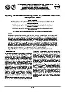
Composition turns a MARMOT project into a tree-shaped structure, a containment tree, with nested component representations. Every box in the tree is treated as a system in its own right. It comprises a component specification, a model defining everything externally knowable about a component, and a component realization, a model about the internal design of the component. Any component in a tree, represents a containment tree in its own right and, thus, another MARMOT project. V. C ASE S TUDY The exterior mirror control system that we used as case study is composed of electrical and mechanical components and control logic. It allows the mirror to be adjusted horizontally and vertically into the desired position. Cars supporting different driver profiles can store the mirror position and recall as soon as the profile is activated. Here, we use a simplified version for brevity of illustration. The system (Figure 2) comprises a microcontroller, a button, two potentiometers, and two servos. It controls the two servo-drives via two potentiometers, and indicates their movement on a small LCD panel. The micro-controller reads values from the potentiometers, converts them to degrees, and generates the needed servo control signals, while at the same time indicating movement and degree on the LCD display. The system stores a position through pressing the button for more than 5 seconds. 1) Requirements Modeling: Use cases describe the requirements in a textual and a graphical representation. Activity diagrams describe the general flow of control, including a UML representation of the target platform (see Figure 3). The actor ’User’ initiates the task of controlling the mirror aptitude rotation, and stores and recalls positions through the button. The system uses an ATMega8 controller and several hardware components. 2) System Architecture: The artifacts shown in Figure 3 represent the ’context realization’ of the mirror system. The context is like a pseudo component realization at the root of the development tree that embeds the system as a regular component. Since components are identified in a top-down manner, a component or containment hierarchy is established. Figure 4a shows the containment hierarchy of the mirror system in its final form. TUD-SERG-2007-020
SERG
Bunse, Gross, Peper – Applying a Model-Based Approach for Embedded System Development
Fig. 3: Requirements-level models of the mirror control system.
(a) Containment hierarchy.
(b) Specification diagrams.
Fig. 4: Mirror control system.
(a) Realization diagrams.
(b) Source code structure
Fig. 5: Mirror control system.
TUD-SERG-2007-020
5
SERG
Bunse, Gross, Peper – Applying a Model-Based Approach for Embedded System Development
3) Component Modeling: Component modeling creates the specification and realization of all software components using class, state, interaction, and activity diagrams, as well as operation schemata. Since timing is critical in embedded systems, the component realization is extended by timing diagrams. Modeling starts at the root of the containment hierarchy, and the top-level component is specified using three different UML models (see Figure 1a): (1) structural model, showing with which other classes the component interacts; (2) functional model, describing the externally visible operations supplied by the component; (3) behavioral model, showing the externally visible state model. Figure 4b shows the model of the Application component. The component specification is further decomposed to the component realization comprising the private design of the component. It describes how the component fulfills its requirements, throug (1) a structural model, showing its internal class architecture, (2) an activity model specifying the algorithms, and (3) an interaction model showing how a group of instances collaborate to realize an operation. These primary artifacts can be enhanced, if needed, by timing diagrams, or other non-functional specifications. Figure 5a depicts some of the realization models of the Application component (interaction model, activity model, and structural model). The models are devised for every component in the containment hierarchy. 4) Implementation: Iteratively devising specifications and realizations is continued until an existing component is found, thereby targeting existing abstractions, or, until it can be implemented (no reuse). Coming to a concrete implementation from the models requires us to reduce the level of abstraction of our descriptions. First, the containment hierarchy is simplified according to the technical restrictions of the used implementation technology. That is through refining the containment hierarchy and mapping it to a UML model with the source code structure of the resulting system (shown in Figure 5b). Second, the models are mapped to source code, either through a code generator, or through manual mapping according to [15]. Figure 6 shows an example code snippet for a servo component. 5) Follow-Up Projects: Reuse can only be assessed in follow-up projects. This is why we devised a number of student assignments, in order to change and extend the original mirror system, with the aim to look at the reuse situations described in [5]. • Porting to different hardware platforms retaining its functionality. We ported the system to a similar processor (i.e., ATMega32, 32Kb Flash, 2Kb RAM, 1Kb EEPROM, 16MhZ), and to an entirely different processor (i.e., PICF, 7Kb Flash, 192Byte RAM, 128Byte EEPROM, 20MHz). Implementing a port on the same type of processor can be automated at the code-level, whereas, a port to a different kind of hardware may affect the models [25]. • We implemented evolving system requirements as to (1) remove the recall position functionality, referred to as Adapt-), and (2) add a defreeze/defog function with a 6
Fig. 6: Source code for the servo component.
humidity sensor and a heater, referred to as Adapt+. Parts of the mirror system were reused in a door control unit, referred to as Door, that incorporates the control of the mirror, power windows, and door illumination. It was realized using three controller boards, and a serial-line communication between the controllers. As development tools, the students used Rational Rose [29] or ARGO UML [1] for modeling, and the AVRStudio/GCC environment [3] for programming and debugging. •
VI. R ESULTS OF THE C ASE S TUDY The presented case study applied the MARMOT approach (Q1) according to the research questions stated (Section III), whereby mapping models to code (Q3) was done manually. We performed a number of measurements in order to get a first impression whether maintainability, portability, and adaptability of embedded systems, developed with MARMOT, may be improved. Table I provides all data concerning model and code size as well as data on quality- (e.g., defect numbers), and process measures (e.g., effort). The figures follow the metric definitions presented in Section III. On first thought, the number of diagrams (ND) seems to be quite high for such a simple example. Modeling at the specification and realization level results in several diagrams plus textual descriptions for each component. Due to MARMOT’s modeling principles, every component has two associated sets of diagrams, one at the specification- and one on the realization level. This increases the number of diagrams and creates the impression of redundant information. However, the separation and explicit distinction of specification and realization provides several advantages (see Sect. IV). In addition, realization TUD-SERG-2007-020
SERG
Bunse, Gross, Peper – Applying a Model-Based Approach for Embedded System Development Project LOC Hex-Size Model
Relative Model Size Reuse in percent
Effort in hours
Quality
(Kbytes) NCM NCOM ND StateCharts Classes Operations Classes Associations Classes
Reuse Fraction New Unchanged Changed Removed Global Hardware Requirements Design Implementation Test Defect Density
Original 310 4 8 15 46 1 3.25 1.375 0 100 0 0 0 26 10 1 9.5 3 2.5 9
ATMega32 310 4 8 15 46 1 3.25 1.375 100 0 95 5 0 6 2 0 0.5 1 2.5 0
PICF 320 4 8 15 46 1 3.25 1.275 97 3 86 14 0 10.5 4 0 1 3 2.5 2
Adapt280 3.5 6 11 33 1 2.5 1.33 100 0 75 5 20 3 0.5 0.5 0.5 0.5 1 0
Adapt+ 350 4.5 10 19 52 0.8 3 1.3 89 11 90 10 0 10 2 1 5 2 2 3
Door 490 6 10 29 64 1 3.4 1.6 60 40 95 5 40 24 8 2 6 4 4 4
TABLE I: Results of the case study.
diagrams are only relevant if the component cannot be reused without modification. It is interesting to see that porting the system to another hardware platform, required only minimal changes to the models (e.g., UML hardware representation, ports, and the like). Thus, MARMOT supports the MDA idea [25] of platform independent modeling. Only in the embodiment step, models become platform-specific. Portability of a system to different platforms is also supported by the high amount of reuse with minimal changes, the low effort, and the low number of defects. Concerning the adaptation of existing systems by adding or removing functionality, the data presented in Table I reveals that MARMOT provides sufficient support. (1) A large proportion of the systems could be reused from the original system. (2) In comparison to the initial development project (i.e., ’Original’), the effort for adaptation is low, i.e., 26 hours initial development vs. 3 or 10 hours for the adapted systems. (3) The quality of the final systems benefits from the quality assurance activities carried out in the initial component development. The promises of component-oriented development concerning time-to-market and quality could be confirmed in our case-study. The effort for the initial system corresponds to standardized effort distributions over development phases such as the ones used by common cost estimation methods [6]. The the effort for the variants is significantly lower, and it supports the assumption that component-oriented development has an effort-saving effect in subsequent projects. In general, porting and adaptation activities within a component-based system development takes place during devising the system variants. On the one hand, our systems are very similar, which explains why reuse works so well. On the other hand, the consistent use of C as programming language and the encapsulation of the hardware (i.e., using a ’Driver’ component) supports the porting, since this requires only changing the hardware capsule. Even if code is not generated automatically (as in TUD-SERG-2007-020
this case-study) the MARMOT component structure permits easy localization of necessary changes and reduction of the number of changes. In order to investigate the development of larger systems that reuse the original system as a whole or to a large extent, we carried out the ’Door’ case study. Table I indicates that 60% of the overall original mirror control system was reused in the new door control system. The integrated mirror control system did not require extended adaptations. The effort and defect density was found to be higher in this case, than those of the other mirror system variants. We could attribute this to the fact that on top of the additional component development, major hardware extensions and intensive quality-assurance activities took place. When compared to the initial development effort and quality of the product, i.e., the original mirror control system, we can observe a positive trend supporting our assumption that embedded systems can be developed quickly, resulting in high quality. Up to this point, we have only examined the effects of following the MARMOT method in developing our case study. However, it is also interesting to compare our experience, gathered so far, with the ways other development methods may be applied in such a setting. This is why we are currently performing two more experiments, developing the same system, using other methods and development teams. In one experiment, we follow the Unified Process [17], with a specific adaptation to embedded system development [5], and in the second experiment, our developers follow an agile development process according to the principles outlined in [14]. In addition, we are interested to see whether or to which extent exchanging personnel is going to affect the factors that we have looked at here. Having many different people work on the same system or components is normal in industry where maintenance or adaptations are not necessarily performed by the people originally involved in a project. We will have the follow-up projects being developed by other development 7
Bunse, Gross, Peper – Applying a Model-Based Approach for Embedded System Development
teams in parallel. VII. S UMMARY AND C ONCLUSIONS The case-study indicates that the promises of model-driven and component-oriented development can also be achieved in embedded system development. However, component-based development projects require an upfront investment before they pay-off. We are aware of the fact, that there may be problems with the validity of our results impeding their generalization. First, the developers were students, and they may not be representative for software professionals, although the results may be useful in an industrial context, because, sometimes, engineers have a negative attitude towards modeling, in contrast to students. Introducing a method requires a steep training curve, even for professionals. Second, volunteers may affect the validity of the study (i.e., selection bias), because they are motivated. In contrast, people in companies are often afraid that new technology takes too much of their time. These differences between study participants and people in real organizations may limit the generalizability of our conclusions. Finally, the systems developed may not be representative in terms of their size and complexity, although we regard them as indicating a trend of possible benefits. The growing interest in the UML provides a unique opportunity to increase the amount of software modeling, and to elevate quality standards. UML 2.0 promises new ways to apply object/component-oriented and model-based development techniques throughout embedded system engineering. However, this chance will be lost, if developers are not given effective and practical means for handling the complexity of such systems, and guidelines for systematically applying them. This paper has outlined the UML modeling practices, which are needed in order to fully leverage the component paradigm in the development of software for embedded systems. Following the principles of encapsulation and uniformity, and describing both levels with a standard set of models, it becomes feasible to model hardware and software components of an embedded system with UML. This facilitates also a ”divide and conquer” approach to modeling, in which a system unit can be developed independently, and it permits new versions of a unit to be interchanged with old versions, provided that they do the same thing. We carried out a case-study, and we are still in the process of gathering more experimental results to assess the MARMOT method. Quantitative and qualitative results of our study indicate that MARMOT supports systematic reuse and thereby reduces development effort, and improves the quality of a software system. However, these results are only a starting point for more elaborate validation and generalization. Besides the extended experiments that we are currently performing, we plan a larger controlled experiment in order receive more experimental data. R EFERENCES [1] ArgoUML Homepage: http://argouml.tigris.org/
8
SERG
[2] C. Atkinson, J. Bayer, C. Bunse, and others, Component-Based ProductLine Engineering with UML, Addison-Wesley, UK, 2001. [3] AVR Studio, Atmel Corp. http://www.atmel.com. [4] C. Bunse, H.-G. Gross, Unifying Hardware and Software Components for Embedded System Development, In: Architecting Systems with Trustworthy Components, R. Reussner, J.A. Staffort, C.A. Szyperski (Eds), Lecture Notes in Computer Science, Vol. 3938, Springer, Heidelberg, 2006. [5] M. Cantor, Rational Unified Process for Systems Engineering, the Rational Edge e-Zine, 2003, http://www.therationaledge.com/content /aug 03/f rupse mc.jsp. [6] S. Cohen, Predicting when Product Line Investment Pays, Proc. of the Second International Workshop on Software Product Lines: Economics, Architectures, and Implications, pages 15-18, 2001. [7] I. Crnkovic, M. Larsson (Eds.), Building Reliable Component-Based Software Systems, Artech House, 2002. [8] B.P. Douglass, Real-Time Design Patterns, Addison-Wesley, 2003. [9] P. Fritzson, Principles of Object-Oriented Modeling and Simulation with Modelica 2.1, Wiley, 2004. [10] H.-G. Gross, Component-Based Software Testing with UML, Springer, Heidelberg, 2005. [11] D. Harel, H. Lachover, A. Naamad, and others, Statemate: A working environment for the development of complex reactive systems, IEEE TSE, 16(4), April 1990. [12] B. Heck, L. Wills, G. Vachtenavos, Software technology for Implementing Reusable, Distributed Control Systems, IEEE Control Systems magazine, February, 2003. [13] J. Hooman, Towards Formal Support for UML-based Development of Embedded Systems, Proc. of the 3d PROGRESS Workshop on Embedded Systems, Technology Foundation STW, 2002. [14] P. Hruschka, C. Rupp, Agile Softwareentwicklung fr Embedded RealTime Systems mit der UML, Hanser, 2002. [15] M.U. Khan, K. Geihs, and others, Model-Driven Development of RealTime Systems with UML 2.0 and C, 3rd International Workshop on Model-based Methodologies for Pervasive and Embedded Software at the 13th IEEE Int. Conf. on Engineering, 2006. [16] H. Kim, C. Boldyreff, Developing software metrics applicable to UML models, Proc. of the 6th ECOOP Workshop on Quantitative Approaches in Object-oriented engineering, Malaga, Spain, June 2002. [17] P. Kruchten, The Rational Unified Process - An Introduction, 2nd edition, Addison-Wesley, 2000. [18] C.F.J. Lange, Model Size Matters, Workshop on Model Size Metrics, 2006 (co-located with the ACM/IEEE MoDELS/UML Conference); October, 2006. [19] K. Lano, Formal Object-Oriented Development. Springer, 1995. [20] L. Lavagno, G. Martin, B. Selic (Eds.), UML for Real Design of Embedded Real-Time Systems, Kluwer, 2003. [21] J. Li, R. Conradi, P. Mohagheghi and others, A Study of Developer Attitude to Component Reuse in Three IT Companies, 5th Int. Conference Product Focused Software Process Improvement, PROFES 2004, Japan, 2004. [22] M. Marcos, E. Estvez, U. Gangoiti and others, UML Modeling of Industrial Distr. Control Systems, Proc. of the 6th Portuguese Conf. on Automatic Control, Portugal, 2004. [23] P. Marwedel, Embedded System Design, (Updated Version), Springer, 2006. [24] The MathWorks, Inc., Simulink Reference, 2005, http://www.mathworks.com. [25] J. Miller, J. Mukerji, MDA Guide 1.0, omg/03-05-01, 2003 (http://www.omg.org/). [26] H.D. Mills, V.R. Basili, J.D. Gannon and others, Principles of Computer Programming: A Mathematical Approach. Allyn and Bacon Inc., 1987. [27] A. Mockus, R.T. Fielding, J. Herbsleb, A Case Study of Open Source Software Development: The Apache Server, Proc. of the 22nd International Conference on Software Engineering, Limerick Ireland, 2000. [28] Object Management Group, UML 2.0 Super-structure Specification, OMG document formal/05-07-04, 2005, http://www.omg.org/cgibin/doc?formal/05-07-04. [29] Rational Rose, http://www.rational.com. [30] B. Selic, G. Gullekson, P.T. Ward, Real-Time Object-Oriented Modeling, John Wiley & Sons, 1994. [31] C. Szyperski, Component Software. Beyond Object-Oriented Programming, Addison-Wesley, 2002.
TUD-SERG-2007-020
SERG
Bunse, Gross, Peper – Applying a Model-Based Approach for Embedded System Development
[32] J. Ventura, F. Siebert, and others, HIDOORS - A High Integrity Distributed Deterministic Java Environment, Proc. of the 7th Int. Workshop on Object-Oriented Real-Time Dependable Systems, USA, 2002
TUD-SERG-2007-020
9
Bunse, Gross, Peper – Applying a Model-Based Approach for Embedded System Development
10
SERG
TUD-SERG-2007-020
TUD-SERG-2007-020 ISSN 1872-5392
SERG