A Flexible Architecture for Future Wireless Local Area Networks Bert Gyselinckx, Wolfgang Eberle, Marc Engels, Curt Schurgers, Steven Thoen, Patrick Vandenameele, Liesbet Van der Perre IMEC Kapeldreef 75 B-3001 Leuven Tel: +32 16 281537, email:
[email protected]
ABSTRACT This paper reports on the activities at IMEC that will lead to a 100Mb/s indoor communication system based on multi-carrier modulation. The goal is to build a wireless local area network, which can compete with today’s wired solutions in terms of cost and performance. It is shown how a dedicated ASIC architecture implements an OFDM modem with 256 carriers that allows transmission of complex symbols (QPSK, 16 QAM) at 50Mbaud/s. It is also demonstrated how adaptive turbo-decoding allows operation close to the Shannon limit and how it can be used to provide quality of service. Adaptive loading of the carriers provides a further capacity enhancement. A gain of 6.5dB in the required signal to noise ratio can be observed compared to standard non-adaptive schemes. Finally, an SDMA scheme with full channel characterization is proposed in order to increase the channel capacity even further. It turns out that even with short training sequences a substantial capacity improvement can be observed. I.
INTRODUCTION
Telecommunications has mainly focussed on plain old telephony service up to now. However, this is changing rapidly. The telecommunications market is predicted to grow by a factor of 20 in the next 15 years. Almost all of this growth will come from data services. In anticipation, standards for data services are being defined. In the wireless society this has led to the 802.11 standard allowing spread spectrum communication at 2Mb/s in the ISM band. Also HIPERLAN seems to be well on its way. It will enable high-speed communication up to 23Mb/s necessary for wireless local area networks (WLAN). In addition, the third generation of cellular systems such as UMTS and IMT-2000 also foresee a mode for data-communication up to 2Mb/s in small cells. However, it is the authors’ belief that wireless broadband communications will only massively be deployed at the moment a performance and price can be offered that is comparable to what a cabled network is offering. Therefore, we are working on the next generation of broadband WLAN, with the goal to achieve an overall network capacity of up to 100 Mb/s comparable to fast ethernet. Such an ambitious target asks for an accurate design of all parts of the system, going from the high
level networking aspects down to the hardware implementation of the functional blocks. Because price is a key enabling factor, emphasis is put on full CMOS integration. In the next section, the network configuration will be defined. Section III describes the characteristics of the indoor channel. Based on this a transceiver architecture is proposed in section IV. II.
NETWORK CONFIGURATION
The envisaged network will consist of powerful basestations connected to a high speed backbone. Each basestation serves as a hub for all communication to and from the different terminals within a cell. To reduce the installation cost it is advantageous for the cells to be quite large. This can be achieved by using the 2.4GHz or 5.7GHz ISM bands. Moreover, this also allows integration of the RF front-end in standard CMOS or BiCMOS technology, in contrast to pico-cellular networks that are being investigated in the 60GHz band. Because there are only few basestations in the network, it is affordable to put of a lot of processing power such as space-time processing and multi-user detection in these stations. The asymmetric network configuration makes it possible to reduce the complexity and the power consumption of the terminals. III.
THE CHANNEL
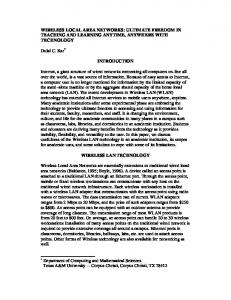
In order to design a modem it is very important to have knowledge of the channel for which it will be used. Therefor, the indoor channel was modeled by means of a ray-tracing technique. Since the envisaged application is a WLAN structured as a star-configuration network consisting of relatively large cells, a typical corridor in an office environment is taken as the geometrical input for the ray-tracing algorithm. Figure 1 shows a typical geographical output of the implemented algorithm displaying the different propagating rays taking multi-path components into account up to a certain threshold for the power loss (which was 30dB for the presented example). The basestation is located in the middle of the corridor, while a mobile terminal is situated in one of the office rooms. The walls are displayed by solid lines, while all dotted lines represent propagation paths.
Basestation
Terminal Figure 3: Frequency response
Figure 1: Typical ray-tracing output From the above picture, it is clear that a multitude of reflections occur in the indoor environment, and consequently a large number of multi-path components arrive in the receiver. The channel impulse response will clearly consist of a number of discrete pulses. The power delay profile for the above example is given in Figure 2. Channel Time Response −65
−70
−75
Power, dB
−80
−85
−90
−95
−100
−105 0
0.02
0.04
0.06
0.08
0.1
0.12
Time, usec
Figure 2: Power delay profile Simulation results show that the delay spread in this environment varies between 10 and 40ns. The delay differences between subsequent multi-path components are of the order of 0.1ns. From the power delay profile, the channel transfer function in the frequency domain was calculated by means of the FFT transform. The result is presented in Figure 3. This frequency response shows a very good agreement with measurement data in a similar environment [2]. It is clear that the indoor propagation channel is frequency selective, with a coherence bandwidth of the order of 5 to 25 MHz (depending on the specific situation). From this observation, we can conclude that using a flat fading model is not reliable for the envisaged bit rate, and that it is possible to improve the system’s performance by exploiting frequency diversity. Dips in the spectrum of up to 30 dB are perceived, meaning that the transmission in these frequency bands will be dramatically degraded.
IV.
TRANSCEIVER ARCHITECTURE
Orthogonal frequency division multiplex (OFDM) is a modulation technique that can exploit frequency diversity. It allows to transmit data on different orthogonal carriers. All these carriers are modulated (PSK or QAM) by a narrow band signal and see a flat fading channel. Because it is unlikely that all carriers are subject to deep fades the receiver will be capable of recovering the originally transmitted sequence. From this reasoning one could conclude that the performance will improve with the number of carriers that are used per OFDM symbol. However, as the number of carriers increases the symbol duration will also increase. From the moment this duration starts exceeding the coherence time of the channel the performance will degrade rapidly. For an 100Mb/s WLAN active on an indoor channel with a coherence bandwidth of 10MHz and a coherence time of 50ms, 256 carriers give an optimal result. The OFDM transceiver architecture under development at IMEC is shown in Figure 4 [1]. It consists of a channel (de)coding module, an adaptive (de)loader, an OFDM modem and an RF front-end with multiple antennas. In the following sections our research activities in these fields will be discussed.
… data
Channel (de)coder
Adaptive (de)loader
OFDM Modulator/ demodulator
Spatial Division Multiple Access Front-end
Figure 4: OFDM transceiver architecture
A. OFDM Modem The implementation target for the OFDM modem is an ASIC in order to achieve the very high data rates. A prototype is under development at the moment. This will perform all OFDM signal processing in the time and frequency domain.
One of the key building blocks of an OFDM modem is the (I)FFT-module. A dedicated pipelined architecture, based on a recursive decomposition, allows the 256points complex FFT to execute in 5µs. This enables transmission of QPSK symbols at 50Mbaud/s. Care was taken to minimize the area and power of the FFT. This is mainly achieved by optimizing the data flow control and the storage of intermediate results. The layout of the (I)FFT macrocell is shown in Figure 5. The main features of this block are summarized in Table 1.
Figure 6 shows the simulated BER in function of Eb/N0 for successive iterations in the decoder. The more decoding iterations are performed the lower the BER, until after 6 to 7 iterations the solution has converged almost to the ideal maximum likelihood decoding. From this figure it becomes clear that for the transmitter received at 8dB one iteration is sufficient to obtain the required BER of 10-3. For the transmitter received at 4dB, 6 iterations will be needed. This adaptive decoding offers two advantages: • The processing power can be reduced for good channels and increased for bad channels, thus obtaining an equal performance for all users. Alternatively, more processing power could be allocated to certain users in order to guarantee a quality of service (QoS) requirement. • The adaptation takes place in the receiver. Therefore, a dedicated communication link to set-up a common encoding and decoding scheme in transmitter and receiver is not needed. 1.E+00
Decoding iterations
BER 1.E-01
Figure 5: (I)FFT layout
1
1.E-02
2
6 Table 1: (I)FFT features Technology Operating frequency Throughput Core size Gate count Memory
Mietec 0.5µ CMOS, TLM, 3V 50 MHz 195 kFFT/s 2.5 * 2.5 mm2 31000 gates 384 bytes RAM
The ASIC consists of programmable data paths that provide the necessary flexibility for on-site tuning depending on the specific application and environment. B. Channel (De)coding Because the indoor channel suffers from severe fading, forward error correcting codes have to be applied in order to obtain an acceptable link quality. Turbo-codes [3] allow operation close to the Shannon limit and are therefore a viable option. As described in section II, all communication passes through the basestation. This will receive the signals from the different mobile terminals all with their own signal to noise ratios. Turbo-codes are parallel concatenated convolutional codes, that are decoded using an iterative scheme. The iterative process of the decoding allows the receiver to tune its channel decoding for each individual transmitter. Assume that all mobiles are transmitting with a particular rate ½ turbo code. The goal at the receiver is to obtain a bit error rate (BER) of 10-3. For a transmission that is received through a good channel the signal to noise ratio per bit (Eb/N0) will be high, assume 8dB. For a transmission through a bad channel Eb/N0 will be low, assume 4dB.
1.E-03
1.E-04
1.E-05 2
3
4
5
6
7
8
Eb/N0
9
Figure 6: Performance of the turbo-decoder for successive iterations C. Adaptive loading Multi-carrier modulation such as OFDM makes it possible to assign a variable number of bits to each carrier depending on the signal to noise ratio (SNR) for each carrier. The SNR in our system is estimated by sending four times a QPSK-modulated PN-sequence over the channel. Let r(i) be the signal received on the i-th carrier. Provided the length of the guard interval was chosen to be longer than the delay spread of the channel, r(i) becomes: r (i ) = PN (i ) ⋅ H (i ) + n(i ) (1) where H(i) stands for the complex channel attenuation factor and n(i) the complex, additive noise on carrier i which is considered to be white and Gaussian. The channel attenuation
~ H is estimated from:
~ H (i )=avg{r (i )} ⋅ PN (i )= H (i )+avg{n(i ) ⋅ PN (i )} (2) Here, avg means taking the average over the 4 PNsequences that were sent. To diminish the second noise term and obtain a better estimation H~ f , a lowpass filter
is applied to the channel estimation. The spectrum of the channel is shown together with the unfiltered channel estimation in Figure 7. A typical result for the filtered channel estimation is shown in Figure 8.
Figure 9: Bit assignment This figure indicates that the dips in the spectrum are not carrying any bits while more bits are transmitted on the carriers with low attenuation. Furthermore, the order of the constellation on the good carriers is low (QPSK or 16-QAM) compared to the order in ADSL, since in general the Eb/N0 is relatively low for the indoor channel. Figure 10 compares the achievable BER for adaptive loading and for plain QPSK on all the carriers for the ray-tracing channel model when the data rate is 100Mbps and a cyclic prefix of 8 bits is used. A 6.5dB gain is observed for BER = 10-2. From the figure, it is clear that a substantial advantage can be achieved by adapting the bit allocation to the spectrum of the fading channel.
Figure 7: Unfiltered channel estimation
Figure 8: Filtered channel estimation The filtered attenuation estimation clearly forms an accurate representation of the given fading channel. The noise power estimation manner
~ N is obtained in a similar
~ ~ N (i ) = avg{| r (i ) − H f (i ) ⋅ PN (i )|2 }
(3)
Using the noise power and attenuation estimations, the bits are assigned in a first step with infinite granularity to the carriers. In the next step, the assigned number of bits is quantized to an even integer. Only even integers are allowed in order to balance the BER on the I and Q components. The third part of the algorithm adapts the number of bits in order to make sure that Rtotal equals the targeted bitrate. Finally, the power of each carrier is adjusted so that all subchannels yield the same BER. In the implementation of the modem this is accomplished by a multiplication per carrier with a power coefficient. A typical bit assignment for the channel estimation in Figure 8 is shown in Figure 9.
Figure 10: BER vs. Eb/No for ray-tracing model The main benefit arises from the fact that the 30dB dips in the spectrum are now not carrying any bits while in QPSK they are the main source of bit errors. To accomplish this, more bits are sent on the peaks of the spectrum. D. Space Division Multiple Access Channel turbo-coding allows operation close to the Shannon limit. In order to increase the capacity further, spatial diversity must be used. In our transceiver, we propose to reuse bandwidth by space division multiple access (SDMA). This technique separates multiple simultaneously transmitting terminals based on their
perfect j = 100 j = 30 j = 16 single user
−1
10
−2
10
−3
10
−4
10
−5
10
−6
10
−7
10
0
2
4
6
8
10
12
14
16
18
SNR
Figure 12: Performance of SDMA algorithm V.
CONCLUSIONS
We presented a transceiver architecture for the next generation of WLAN. The prototype OFDM modem ASIC will allow a network capacity of 100Mb/s. Further research on turbo-coding, adaptive loading and spatial diversity will allow to increase the capacity even further.
Channel estimation at fading rate
REFERENCES
… Symbol detection at symbol rate
RLS Channel Estimation
0
10
BER
different spatial properties by processing the signals received at an antenna array. Because the indoor channel is characterized by heavy multipath distortion, the signals arriving at the receiver come from all directions. Therefore, techniques based on beam forming are not appropriate. Instead, SDMA algorithms based on full channel identification have to be used. For the further analysis it is assumed that the total network capacity of 100Mb/s is shared between 4 users, each having a capacity of 25Mb/s. Single carrier BPSK modulation is assumed to simplify the reasoning. Therefore, a bandwidth of 25MHz is needed for the 4 users. A symbol will last 40ns. Assuming an indoor channel with a delay spread of 40ns, the last arriving signal will have a delay of approximately 120ns, requiring a 3 tap equalizer in the receiver to remove ISI. The channel identification is based on the transmission of a training sequence that is known a priori by the receiver. To limit the capacity loss resulting from this sequence, a fast converging recursive least squares (RLS) algorithm is used to determine the channel parameters. Furthermore, the four users are trained simultaneously. Because the fading rate of the indoor channel is in the order of 10Hz, the channels estimation can run at a much slower rate than the actual symbol detection (Figure 11).
[1]
… [2]
Figure 11: Receiver with channel estimation at fading rate BER versus SNR simulation results for the SDMA receiver with RLS based channel estimation and MLSE symbol detection are shown in Figure 12. The dashed curve labeled perfect shows the performance of the reception of four simultaneous users with a four antenna receiver, in the case of perfect channel estimation. The performance with the imperfections of the RLS channel estimation included is given by the plain curves. The training sequence length j is used as a parameter. It is observed that a 30 symbol training sequence already shows similar performance to perfect 25Mb/s single user single-antenna Viterbi reception, which is the bold dashed curve.
[3]
[4]
[5]
[6]
W. Eberle, L. Van der Perre, B. Gyselinckx, M. Engels, I. Bolsens. Design Aspects of an OFDM Based Wireless LAN with Respect to ASIC Integration. Proc. of the 2-nd OFDMFachgespräch, Braunschweig, Germany, September1997. G.J.M. Janssen, P.A. Stigter, and R. Prasad. Wideband Indoor Channel Measurements and BER Analysis of Frequency Selective Multipath Channels at 2.4, 4.75, and 11.5 GHz. IEEE Trans. on Communications, Vol. 44, No 10, Oct 1996, pp. 1272-1281. C. Berrou, A. Glavieux, P. Thitimajshime, “Near Shannon limit error-correcting coding and decoding: Turbo-code,” Proceedings ICC’93, Geneva, Switzerland, May 1993, pp. 1064-1070 C. Schurgers, L. Van der Perre, M. Engels, H. De Man, "Adaptive Turbo Decoding for Indoor Wireless Communication," (submitted), ISSSE, Pisa, Italy, SeptemberOctober 1998. L. Van der Perre, S. Thoen, P. Vandenameele, B. Gyselinckx, M. Engels, "Adaptive loading strategy for a high speed OFDMbased WLAN," (submitted), Globecom 98, Sydney, Australia, November 1998. P. Vandenameele, L. Van der Perre, B. Gyselinckx, M. Engels, H. De Man, "An SDMA Algorithm for High-Speed Wireless LAN," (submitted), Globecom 98, Sydney, Australia, November 98.