ref ellipse circle big ellipse shifted ellipse thick ellipse a (cm). 3.5 ... 2.5 w (cm). 1. 1. 1. 1. 2 x0 (cm). 0.1. 0.1. 0.1. 1.4. 0.1 y0 (cm) -1.4. -1.4. -1.4. 0. -1.4 a b c d e.
A Flexible Design Algorithm for Single-shot 2D Circular/Elliptical OVS RF Pulses X. Wu1, N. Powell1, M. Marjanska1, M. Garwood1, K. Ugurbil1, and P-F. Van de Moortele1 Center for Magnetic Resonance Research and Radiology Department, University of Minnesota, Minneapolis, MN, United States
1
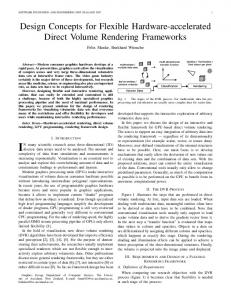
Introduction: Outer Volume Suppression (OVS) is used to saturate unwanted MR signals in spectroscopy. Typically, OVS is performed with multiple conventional (e.g., sinc) pulses and suffers from low efficiency and high Specific Absorption Rate (SAR). We have previously introduced a new OVS RF pulse design (1) consisting of a constant frequency offset RF pulse applied together with sinusoidal temporal gradient modulations. It was experimentally demonstrated that this technique allows, in a single RF excitation, for circular and elliptic shaped 2D OVS patterns (1). However, it remains challenging to alter the geometry of these patterns, a flexibility that is required in human brain studies in order to match OVS patterns with anatomical targets defined for each patient. We introduce a new algorithm to design these pulses, capable of large geometry adjustment and of preserving a constant OVS width. We verify experimentally its properties in a phantom on a human 9.4 T scanner. Pulse Design Principle: An RF pulse with constant magnitude and time varying offset frequency is applied with a time varying 2D gradient in order to achieve RF excitation along a curved target. The time-dependent gradient continuously reorients the plane of frequency selection in space. This, together with the appropriately designed RF pulse, creates the proper condition to accomplish rapid passage (2) in a spatial location moving along a curved trajectory. We need to define the gradient strength (Gx, Gy), the gradient orientation and the RF offset frequency. To preserve a constant curve thickness (bandwidth), we constrain the net gradient strength G = (Gx2+Gy2)1/2 to be constant and calculate it with G = s(Tpw)-1; here s is an empirically determined scaling factor, and Tp and w are the desired pulse duration and bandwidth, respectively. We apply the gradient and RF in such a way that at each moment the on-resonance isochromats are disposed along a plane tangent to the curve. With the origin at the gradient isocenter, this problem becomes: given a point on a curve, find the tangent line at that point and the distance from the origin to this tangent line. The orientation of the gradient is perpendicular to this line, while the distance defines the RF offset frequency. Let's assume for example an excitation curve defined Fig.1. Pulse design geometry. by an ellipse, xe(t) = acosθ(t)+x0 and ye(t) = bsinθ(t)+y0, where t is the time variable (Fig. 1). In this case, the gradient orientation and the distance become φ(t) = arctan[b-1atanθ(t)] and rB(t) = {[c(t)bcosθ(t)]2+[c(t)asinθ(t)]2}1/2, respectively; here c(t) = [ab+ay0sinθ(t)+bx0cosθ(t)][a2sin2θ(t)+bcos2θ(t)]-1. The gradient waveforms are then given by Gx(t) = Gcosφ(t), Gy(t) = Gsinφ(t), and the RF offset frequency by ωrf(t) = - γGrB(t). Table 1. Main specifications for pulse design. ref ellipse circle big ellipse shifted ellipse thick ellipse Materials and Methods: For demonstration purpose, we imaged the 3.5 3.5 5.5 3.5 3.5 OVS excitation pattern rather than the corresponding suppressed signal. a (cm) 2.5 3.5 4.5 2.5 2.5 An 8ch RF Transmit (Tx), 9.4 T human scanner was used (Varian, USA). b (cm) w (cm) 1 1 1 1 2 An elliptical 8ch Transceiver RF array (3,4) was loaded with a 1.8 L 0.1 0.1 0.1 1.4 0.1 spherical doped water phantom. Gradient and RF pulses were designed x0 (cm) -1.4 -1.4 -1.4 0 -1.4 with a constant angular velocity of on-resonance traversal on the ellipse y0 (cm) (i.e., θ(t) = ωt). We designed OVS patterns of different shapes, sizes, positions and bandwidths within an axial slice of 14 cm in diameter. The main specifications for those pulses are displayed in Table 1, where the numbers in red show the parameters that differed from a reference ellipse (first column). Tp = 2 ms, unless specified otherwise. Excitation patterns were experimentally imaged using a spin echo (SE) sequence where the slice selective excitation module was replaced with the OVS excitation (slice thk = 5 mm, FOV = 20 x 20 cm2, matrix = 128 x 64, TR/TE = 300/26 ms). Tx B1 heterogeneity was mitigated with static B1 shimming (5). A regular SE image with sinc RF excitation was also obtained with the same imaging parameters in order to appreciate image intensity variations due to B1 field inhomogeneities. Numerical simulations of the excitation patterns were performed assuming a uniform B1 in the image plane. a Results and Discussion: Based on these calculations, the RF offset frequency continuously varied through time, and the gradient waveforms were not pure sinusoids (Fig. 2). Numerical simulations closely matched the experimental results (Fig. 3). Residual differences between the two were mostly attributed to ΔB0 and gradient b imperfections. As expected, image intensity variations due to RF coil B1 inhomogeneity (Fig. 3a) were consistently observed in all images. Another expected source of signal non-uniformity was the varying excitation traversal rate c along the ring, which may be addressed with a constant traversal speed of excitation target. It will be interesting to determine whether Tx B1 inhomogeneity induced variations can be addressed by embedding dynamic B1 shim in Fig.2. RF amp (a), phase (b), and Gx, Gy (c) vs. time. the pulse design, modulating RF phase and magnitude of each channel through time. As previously shown, periodic concentric excitation rings were generated outside the first, main excitation ring (Fig. 3b-k). However, when using OVS RF pulses in vivo to suppress signal from the skin, only this innermost ring is of interest and the other ones can be ignored. Increasing the bandwidth decreases the gradient strength, and thus increases sensitivity to ΔB0. Therefore, a shorter RF pulse was utilized (1 ms instead of 2 ms) for the thicker ellipse pattern (Fig. 3f). Although an ellipse was used in the current study, the algorithm could be used to obtain any convex curved pattern and extended to account for ΔB0. Conclusions: We have introduced a new method to calculate 2D, single-shot OVS RF pulses, allowing for flexible control of pattern geometry. The properties of this method have been experimentally verified at 9.4 T. a b c d e f Standard hardware is required to utilize these RF pulses. References: 1. N. Powell, et al., ISMRM 2008, p1327. 2. R. Ernst, AMR 2:1-135(1966). 3. G. Adriany et al., MRM 53:434-45(2005). 4. T. Vaughan et al., MRM 56:127482(2006). 5. T.-H. Chang et al,. ISMRM 2008, p1088. Acknowledgments: W. M. KECK Foundation. NIH: EB006835, PAR-02-010, EB007327, P41 RR008079 and P30 NS057091.
Proc. Intl. Soc. Mag. Reson. Med. 17 (2009)
g
h
i
j
0
1
0
0
2
0
0
3
0
0
4
0
0
5
0
0
0
1 0 0
2 0 0
3 0 0
4 0 0
5 0 0
0
1 0 0
2 0 0
3 0 0
4 0 0
5 0 0
k
Fig.3. Experiments (top row) and simulations (bottom row). (a) ref SE image. (b,g) ref ellipse. (c,h) circle. (d,i) big ellipse. (e,j) shifted ellipse. (f,k) thick ellipse (Tp=1ms).
4503