Mar 5, 2004 - Arithmetic coding, bit-plane coding, Digital Cinema, JPEG 2000, line-based, ... For this reason a complete hardware JPEG 2000 decoder ...... channels), to secure protocols for communications, digital signatures, payTV, ...
A Flexible, Hardware JPEG 2000 Decoder for Digital Cinema Antonin Descampe, Student Member, IEEE, Franc¸ois Devaux, Student Member, IEEE, Ga¨el Rouvroy, Student Member, IEEE, Jean-Didier Legat, Member, IEEE, Jean-Jacques Quisquater, Member, IEEE, and Benoˆıt Macq, Senior Member, IEEE
Abstract The image compression standard JPEG 2000 proposes a large set of features, useful for today’s multimedia applications. Unfortunately, it is much more complex than older standards. Real-time applications such as Digital Cinema require a specific, secure and scalable hardware implementation. In this paper, a decoding scheme is proposed with two main characteristics. First, the complete scheme takes place in an FPGA without accessing any external memory, allowing integration in a secured system. Second, a customizable level of parallelization allows to satisfy a broad range of constraints, depending on the signal resolution. The resulting architecture is therefore ready to meet upcoming Digital Cinema specifications.
Index Terms Arithmetic coding, bit-plane coding, Digital Cinema, JPEG 2000, line-based, wavelet transform.
Manuscript received March 5, 2004. This work was supported by the Walloon Region, Belgium, through the TACTILS project. A. Descampe, F. Devaux and B. Macq are with the Communications and Remote Sensing Laboratory (TELE), Catholic University of Louvain (UCL), Belgium. E-mail: {descampe,devaux,macq}@tele.ucl.ac.be. G. Rouvroy, J-D Legat and J-J Quisquater are with the Microelectronics Laboratory (DICE), Catholic University of Louvain (UCL), Belgium. E-mail: {rouvroy,legat,jjq}@dice.ucl.ac.be. A. Descampe is funded by the Belgian NSF. March 5, 2004
DRAFT
1
A Flexible, Hardware JPEG 2000 Decoder for Digital Cinema I. I NTRODUCTION The development and diversification of computer networks as well as the emergence of new imaging applications have highlighted various shortcomings in today’s image compression standards, such as JPEG. In the DCT-based approaches (JPEG, MPEG) any change of resolution or any new rate-quality point is reached through decoding and re-encoding of the images. On the contrary, the new image compression standard JPEG 2000 [1] enables inherently such scalability: according to the available bandwidth, computing power and memory resources, different resolution and quality levels can be extracted from a unique bit-stream. In addition to this, the JPEG 2000 baseline (part I of the standard) also proposes other important features: good compression efficiency, even at very low bit rates, lossless and lossy compression using the same coder, random access to the compressed bit-stream, error resilience, region-of-interest coding. A comprehensive comparison of the norm with other standards, performed in [2], demonstrates the functionalities improvements provided by JPEG 2000. The algorithm enabling all these features is composed by a wavelet transform (DWT) followed by an entropy coding of each subband. In the JPEG 2000 standard, the wavelet transform may use two filter-banks: a lossless 5-3 and a lossy 9-7. The entropy coding step consists in a context modeling with an arithmetic coding. The drawback of JPEG 2000 algorithm is that it is computationally expensive, much more for example than a cosine transform (DCT) followed by an Huffman coding, which are the techniques used in JPEG [2]. This complexity can be a problem for real-time applications. Digital Cinema is one of these real-time applications. As explained in [3], edition, storage or distribution of video data can largely take advantage of the JPEG 2000 feature set. Moreover, a video format named Motion JPEG 2000 has been designed, which encapsulates JPEG 2000 frames and enables synchronization with audio data [4]. In the Digital Cinema scenario, the movies are compressed and ciphered off-line and then transmitted securely in the movies theater. The compressed movies are stored locally and have to be decompressed in real-time at each exhibition. For this reason a complete hardware JPEG 2000 decoder architecture intended for Digital Cinema has been developed. It has been designed in VHDL, synthesized and implemented in an FPGA (Xilinx XC2V6000 [5]). It takes about 90% of the chip and the estimated frequency of operation March 5, 2004
DRAFT
2
is 90 Mhz. The proposed architecture decodes images line by line without accessing any external memory, allowing integration in a secured system. It is highly parallelized and depending on available hardware resources, it can easily be adapted to satisfy various formats, from Digital Cinema to Video-on-Demand, and specific constraints like secure decoding, lossless capabilities, and higher precision (over 8 bits per pixel-component). The three main blocks of the architecture are an Inverse DWT block (IDWT), a Context Modeling Unit (CMU) and an Arithmetic Decoding Unit (ADU). Concerning the DWT part, many architectures have been published in the literature. Fast and efficient designs are based on the lifting scheme [6] and consist of separated or combined 5-3 and 9-7 transforms [7]–[10]. The last two papers also propose low-memory wavelet image compressions based on a linebased transform. The most recent and efficient work [10] details an FPGA architecture combining 5-3 and 9-7 wavelet filters with one decomposition level and also proposes a solution to minimize the number of lines kept in internal buffers. Concerning the wavelet part of our paper, a complete FPGA implementation of the inverse discrete wavelet (IDWT) with 5-level of recomposition is achieved. In order to meet lossless real-time applications and cost constraints, our design is focused on the 5-3 transform and is also based on reduced internal memories. Some papers detail a complete hardware entropy coding [11]–[13]. Each of these papers propose a different and interesting design approach of the entropy coding, but all are based on ASIC technology. We propose an FPGA approach of this scheme based on the parallel mode defined in JPEG 2000. This parallelization allows us to propose an innovating approach with interesting properties. Our context modeling part deals with three pass blocks in parallel and, compared to [11], reduces by 25% the RAM used. References [12], [13] also propose an ASIC arithmetic encoding architecture. In comparison with them, we present an FPGA arithmetic decoding design. We take advantage from the parallel mode mentioned above, which significantly improves the global throughput of the entropy decoding chain. Complete implementations have also been recently described in one academic paper [12] and at least two industrial papers [14], [15]. Nevertheless, the commercial papers briefly show the global architecture and give direct results without important design details. The flexibility of our FPGA decoder and the large image size managed in real-time make our paper an attractive solution for the upcoming Digital Cinema specifications. The rest of the paper is organized as follows. Section II briefly describes the JPEG 2000 algorithm. In Section III, we present our decoder architecture as well as our implementation choices. The main blocks of the architecture are described more in details in Sections IV to VI. The performance of the system is discussed in Section VII and the paper is concluded in Section VIII. March 5, 2004
DRAFT
3
Wavelet Transform
cblk
cblk
HL
cblk
cblk
HH
cblk
cblk
Entropy coding
Segment Segment
...
Tile LH
Segment
Rate allocation + Bit-stream organization
header
packet
packet
header
JPEG 2000 code-stream
Image
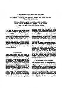
Fig. 1.
Coding steps of the JPEG 2000 algorithm.
II. JPEG 2000
OVERVIEW
In this Section, concepts and vocabulary useful for the understanding of the rest of the paper are presented. For more details, one should refer to [1] or to [16]. Although a decoder architecture was achieved, encoding steps are explained here because their succession is easier to understand. Decoding process is achieved by performing these steps in the reverse order. Fig. 1 presents the coding blocks which are explained below. First of all, the image is split into rectangular blocks called tiles. They will be compressed independently from each other. An intra-component decorrelation is then performed on the tile: on each component a discrete wavelet transform is carried out. Successive dyadic decompositions are applied. Each of these uses a bi-orthogonal filter bank and splits high and low frequencies in the horizontal and vertical directions into four subbands. The subband corresponding to the low frequencies in the two directions (containing most of the image information) is used as a starting point for the next decomposition, as shown in Fig. 1. The JPEG 2000 Standard performs five successive decompositions by default. Two filter banks may be used: either the Le Gall (5,3) filter bank prescribed for lossless encoding or either the Daubechies (9,7) filter bank for lossy encoding. Every subband is then split into rectangular entities called code-blocks. Each code-block will be compressed independently from the others using a context-based adaptative entropy coder. It reduces the amount of data without losing information by removing redundancy from the original binary sequence. “Entropy” means it achieves this redundancy reduction using the probability estimates of the symbols. Adaptivity is provided by dynamically updating these probability estimates during the coding process. And “context-based” means the probability estimate of a symbol depends on its neighborhood (its “context”). Practically, entropy coding consists of •
Context Modeling: the code-block data is arranged in order to first encode the bits which contribute to the largest distortion reduction for the smallest increase in file size. In JPEG 2000, the Embedded Block Coding with Optimized Truncation (EBCOT) algorithm [17] has been adopted to implement
March 5, 2004
DRAFT
4
this operation. The coefficients in the code-block are bit-plane encoded, starting with the most significant bit-plane. Instead of encoding the entire bit-plane in one coding pass, each bit-plane is encoded in three passes with the provision of truncating the bit-stream at the end of each coding pass. During a pass, the modeler successively sends each bit that needs to be encoded in this pass to the Arithmetic Coding Unit described below, together with its context. •
Arithmetic Coding: the Context Modeling step outputs are entropy coded using a MQ-coder, which is a derivative of the Q-coder [18]. According to the provided context, the coder chooses a probability for the bit to encode, among predetermined probability values supplied by the JPEG 2000 Standard and stored in a look-up table. Using this probability, it encodes the bit and progressively generates code-words, called segments.
During the rate allocation and bit-stream organization steps, segments from each code-block are scanned in order to find optimal truncation points to achieve various targeted bit-rates. Quality layers are then created using the incremental contributions from each code-block. Compressed data corresponding to the same component, resolution, spatial region and quality layer is then inserted in a packet. Packets, along with additional headers, form the final JPEG 2000 code-stream. This algorithm overview shows the main JPEG 2000 weakness: its complexity. Compared to JPEG, the DWT handles each tile entirely while DCT works on small 8 × 8 blocks. Regarding to entropy coding, arithmetic coding used in JPEG 2000 compresses data one bit at a time while the JPEG Huffman coding only deals with coefficients. III. P ROPOSED
ARCHITECTURE
In this section, we first present the constraints we used for our JPEG 2000 decoder architecture. Implementation choices made in order to meet these constraints are then explained. Finally, the complete architecture is presented.
A. Constraints As our decoder is designed for real-time Digital Cinema processing, three main constraints have been identified: •
High output bit-rate: all implementation choices have been made in order to increase this bit-rate. With the Xilinx XC2V6000 used, we wanted our architecture to satisfy at least the 1080/24p HDTV format. This means an output rate of about 1200 megabits per second (Mbps) for 8-bit 4:4:4 images.
March 5, 2004
DRAFT
5
Encrypted and compressed bit-stream
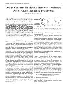
Fig. 2.
•
FPGA
Decryption
Decompression
Watermarking
Watermarked bit-stream
A secured decoding scheme.
Security: no data flow may transit outside the FPGA if it is not crypted or watermarked. This constraint enables a completely secured decoding scheme, as the decompression block might be inserted between a decryption block and a watermark block, all these three blocks being in the same FPGA (Fig. 2).
•
Flexibility: computationally intensive parts of the decoding process must be independent blocks which can easily be duplicated and parallelized. This allows the proposed architecture to satisfy a broad range of output bit-rates and resources constraints. The design can therefore be easily adapted to upcoming Digital Cinema standards.
B. Implementation choices To meet these constraints, the following implementation choices have been made. No external memory has been used, meeting the security constraint and also increasing the output bit-rate, as the bandwidth outside the FPGA is significantly slower than inside. As internal memory resources are limited, large image portions cannot be stored and the decoding process must be achieved in a line-based mode. In order to increase the output bit-rate, three parallelization levels have been used. The first one is a duplication of the entire architecture which allows various tiles to be decoded simultaneously. The second parallelization level tries to compensate the computation load difference between the entropy decoding unit (EDU) and the inverse discrete wavelet transform. The EDU is indeed much more complex than the IDWT and must therefore be parallelized. This is possible as each code-block is decoded independently from the others. Finally, a third level of parallelization, known in the JPEG 2000 standard as the parallel mode, is obtained inside each EDU. By default, each bit-plane is decoded in three successive passes but, by specifying some options ( [19], p.508) during the encoding process, it becomes possible to decode the three passes simultaneously. This implies that each EDU contains one Context Modeling Unit (CMU) and three Arithmetic Decoding Units (ADU). March 5, 2004
DRAFT
6
cblk 1 LL3
HL3
HL2 LH3
HH3
LH2
Fig. 3.
cblk 2 ...
HH2
cblk n
Customized code-block dimensions.
Another option specified during the encoding process that increases the output bit rate of the decoder is the bypass mode ( [19],p.504). The more correlated the probability estimates of the bits to encode are, the more efficient the ADU is. This is especially the case in the most significant bit-planes while the last bit-planes are most of the time totally uncorrelated. With the bypass mode enabled, these last bit-planes are therefore raw-coded1. Some choices about image partitioning have also been made. A 512 × 512 tile partition avoids the use of an external memory and enables one of the parallelization level mentioned above. Inside each tile, even if the maximum code-block size specified in the norm is 4,096 pixels, it does not exceed 2,048 pixels in our implementation. As we shall see, this does not induce any significant efficiency loss but allows a 50% memory resources saving. Furthermore, the code-block dimensions have been chosen so that each of them systematically covers the width of the subband to which it belongs (Fig. 3). As the IDWT processes the subband data line by line, such code-block dimensions enable a line-based approach of the overall process, reducing the size of the image portions to store between EDU and IDWT. These last implementation choices (parallel mode, bypass mode and image partitioning) imply an efficiency loss during the encoding process. Table I shows the corresponding PSNR losses for various compression ratios. In comparison to the improvements provided by these choices, quality losses are quite reduced, especially for small ratios which are the ones used for Digital Cinema. Another choice has to be made in order to enable a line-based processing of the image. To reconstruct one line of the original image, the IDWT needs the corresponding line at each resolution. In order to minimize the image portions size to store, data inside the bit-stream is organized so that the whole 1
This means they are inserted “as is” in the bit-stream.
March 5, 2004
DRAFT
7
TABLE I AVERAGE PSNR FOR A
Compression
SET OF IMAGES
1920 × 1080, 8 BPP.
PSNR [dB]
ratio
Default options
Options used
1:50
37.36
35.83 (-1.53)
1:25
40.10
38.74 (-1.36)
1:10
43.25
42.40 (-0.85)
1:5
45.85
45.31 (-0.54)
compressed data corresponding to a specific spatial region of the image is contiguous in the bit-stream. Such a data ordering scheme corresponds to one of the five progression orders proposed in the JPEG 2000 Standard. If another progression order is used to encode the images, the compressed bit-stream will have to be re-ordered to be compliant with our implementation. A last implementation choice aims at achieving some lightweight operations in software. These operations are mainly data handling and are easily implemented using pointers in C. Headers and markers (needed by these operations) are therefore not ciphered on the contrary of packet bodies, keeping the decoding process secure. As it can be seen, some options, known by any universal JPEG 2000 encoder, must be specified during the encoding process. Our architecture is unable to decode a JPEG 2000 code-stream that has not been encoded using these options. As this architecture is dedicated to decode Digital Cinema at the highest output bit-rate, we did not consider it efficient to produce a universal decoder. C. Architecture Fig. 4 presents the hardware parts of our architecture. Each EDU contains three ADUs which reflect the parallel mode. The bypass mode is also illustrated by the bypass line under each ADU. The Dispatch IN and OUT blocks are used to dissociate the entropy decoding step from the rest of the architecture and enable the flexibility mentioned above. When Dispatch IN receives a new JPEG 2000 code-stream from the PCI, it chooses one of the free EDUs and connects the data stream to it. Dispatch OUT retrieves decompressed data from each EDU and connects it to the correct subband FIFO. In this way, a maximum of EDUs are always used simultaneously. ADU, CMU and IDWT blocks are explained more in details below.
March 5, 2004
DRAFT
8
IDWT
ADU
FIFO
ADU
FIFO
ADU
FIFO
ADU
FIFO
ADU
FIFO
IDWT 3
FIFO (3x)
IDWT 2
. . .
. . .
FIFO (3x)
IDWT 1
FIFO
ADU
FIFO
ADU
FIFO
FIFO (3x)
IDWT 0
towards the display
ADU
CMU
FIFO
. . .
O U T
I N
FIFO (3x)
EDU
EDU
Fig. 4.
IDWT 4
EDU
FIFO
PCI
FIFO (4x)
FIFO
D I S P A T C H
FIFO
CMU
ADU
CMU
D I S P A T C H
FIFO
FIFO
DC Shift
Proposed architecture.
IV. C ONTEXT M ODELING U NIT A. EBCOT algorithm In the EBCOT algorithm, each code-block is encoded along its bit-planes, beginning with the most significant one, and each bit-plane is encoded in three passes. Each bit of the bit-plane is encoded only once, by one of the three passes. When one of the EBCOT passes has to encode a bit, it sends this bit along with its context to the MQ-coder. The MQ-coder will then generate the compressed bit-stream. The decoding process is very similar: the main difference is that the EBCOT only sends the context to the MQ-decoder, and then waits for the decoded bit. This implies a little efficiency loss given that the EBCOT is inactive while waiting for the MQ-decoder answer. To achieve a specific bit-rate while guaranteeing the minimum distortion for this bit-rate, the EBCOT defines a set of optimal truncation points during the code-block coding process. If each bit-plane was encoded in one pass, the only optimal truncation points would be the bit-planes end. Distributing the bits of a bit-plane between three subgroups according to the distortion reduction they bring defines two March 5, 2004
DRAFT
9
CMU bit-stream
ADU
bit-stream
ADU
Pass 1
Pass 2
Internal RAM
Synchronization Block Code-block 1 IDWT
bit-stream
ADU
Pass 3
Code-block 2 Output RAM
Fig. 5.
Simplified view of the CMU architecture.
additional optimal truncation points inside each bit-plane and allows a more precise bit-stream truncation. More precisely, each coefficient in a code-block has three state variables and each bit in a bit-plane has two [20]. These state variables indicate for example if the coefficient has already become significant, or if the bit in the bit-plane has already been processed by one of the three passes. They are held up to date by the EBCOT and used to fix in which pass the bit has to be encoded. They also influence the neighbors context. B. CMU architecture A simplified view of the adopted CMU architecture is presented in Fig. 5 and is based on the one developed by Andra et al. in [11]. The three Pass Blocks are inter-connected and linked to an ADU. The state variables are stored in an internal RAM and the Synchronization Block organizes the decoding. During this process, the decoded code-block is sent to an Output RAM connected to the IDWT. The parallel mode allows the three Pass Blocks to decode simultaneously the same bit-plane. To make this possible, each pass must be delayed from two columns compared to the previous one. As represented on Fig. 6, the first Pass Block receives the state variables corresponding to the last decoded bit-plane from the internal RAM. When a column is decoded, the state variables move from one pass register to another. This register-based architecture offers a significant memory reduction and a higher output rate. The memory reduction is made possible because one of the two state variables related to each bit in a bitplane doed not need to be stored in the RAM. Compared to [11], only 75% of the internal RAM is necessary. The state variables synchronously shifting from one pass to another are easily treated, and less transfers to the internal RAM have to be performed. The Synchronization Block has two functions. First, it allows each pass to decode a column at its March 5, 2004
DRAFT
10
RAM
Pass 1 register Back to the RAM
Pass 2 register
Pass 3 register Bits analyzed by the passes
Fig. 6.
Communication between the state variables registers of each pass.
own rhythm without loosing a global synchronization of the CMU. Second, it manages the code-blocks characteristics (size, number of bit-planes, ...) and handles the borders. This allows the three Pass Blocks to work the same way either they decode bits inside a code-block or on its border and enables highly simplified control parts for these three blocks. An Output RAM progressively receives the decoded code-block from the third pass. Since the EBCOT algorithm complexity makes the CMU the slowest component of the decoder, the memory designed to receive the decoded code-blocks is able to take care of two code-blocks at a time. In this way, the EDU can begin to decode a new code-block while the previous one is still being processed by the IDWT. The CMU decodes one bit in 2 clock cycles2 in simple code-blocks and up to 4 clock cycles in more complex code-blocks. The complexity of a code-block depends on the position of the code-block in the image: in low frequencies, where most of the picture’s information stands, they are much more complex than in high frequencies, but their size is much smaller (for an image of 5 levels of resolution, 0.04% of the coefficients belong to the lowest resolution, and 75% to the highest). For the whole image, averaging on all the code-blocks, the CMU takes 2.1 clock cycles to output one bit. Table II presents the Virtex-II FPGA resources used after synthesis (XST tool) and implementation (ISE 6.01 tool). The proposed CMU design contains various optimizations in comparison with [11], most of them due to an efficient use of the parallel mode. The optimal communication system between the three autonomous Pass Blocks and the independent code-blocks management by the Synchronization Block 2
This result does not take into account the ADU decoding time.
March 5, 2004
DRAFT
11
TABLE II S YNTHESIS RESULTS OF ONE CMU IN A XC2V6000. Slices
543 over 33,792 (1.6%)
Look-Up Tables
810 over 67,584 (1.1%)
RAM blocks (18kbits)
1 over 144
Clock frequency
156 MHz
MPS = Ai+1 (1 - Q) Ai
MPS (1 - Q)
LPS (Q) Ci+1 LPS (Q)
Ci
Fig. 7.
Successive interval subdivisions in the MQ-coder (MPS-encoding case).
allows a significant improvement of the decoding speed. This CMU architecture is generic and decodes all size of code-blocks: from small 128 coefficient code-blocks with only one non-zero bit-plane to 2048 coefficient code-blocks with all non-zero bit-planes. V. A RITHMETIC D ECODING U NIT A. MQ algorithm The basic idea of a binary arithmetic coder is to find a rational number between 0 and 1 which represents the binary sequence to encode. This is done using successive subdivisions of the [0; 1] interval based on the symbols probability. Fig. 7 shows the conventions used for the MQ-coder. C is the starting point of the current interval and also represents the current rational number used to encode the binary sequence. A is the size of the current interval. Q is the probability of the Least Probable Symbol (LP S ) and is used to subdivide the current interval. According to the symbol we want to encode (M P S or
March 5, 2004
DRAFT
12
LP S ), we use respectively: Ai+1 = Ai ∗ (1 − Q) and Ci+1 = Ci + Ai ∗ Q Ai+1 = Ai ∗ Q and Ci+1 = Ci
During the coding process, renormalization operations are performed in order to keep A close to unity. This leads to the following simplified equations, respectively for an MPS and an LPS: Ai+1 = Ai − Qe and Ci+1 = Ci + Qe Ai+1 = Qe and Ci+1 = Ci
At each step, the Qe -value (estimated Q-value) is retrieved from two serial look-up tables, using the context provided by the CMU. In a reverse way, the decoding process consists in deciding to which interval (MPS or LPS) belongs the rational number provided and in progressively expanding the current interval until [0; 1]. B. ADU architecture As mentioned above, a drawback of the decoding process is that the CMU must wait for the ADU’s answer before going on with the following bits to decode. Priority has therefore been given to the highest ADU bit-rate, at the expense of an increase in resources needed. A deep analysis of the MQ-algorithm shows that only four steps are needed to decode one symbol: 1) Load: given a context, it retrieves the corresponding probability and the MPS-value. 2) Compute: during this step, the arithmetic operations needed to decide if a M P S or a LP S must be decoded are performed. These are only three 16bits-subtractions: AQe = Ai − Qe
(1)
CQe = Ci − Qe
(2)
A2Qe = Ai − 2 ∗ Qe
(3)
3) Decide: using the results of the compute step, the decoded bit is found an returned to the CMU which can then update its data and compute the next context to send. During this step, the Ai+1 and Ci+1 values are also deduced from the results of (1) to (3). In some cases, an update of the probability associated with the current context occurs.
March 5, 2004
DRAFT
13
LOAD
COMPUTE
DECIDE
switch
IN : CX
Qe
RamMQ
A-2*Qe
nmps
A
nlps
C
SUB (3x)
C-Qe
DECIDE
A-Qe
mps
NbShift
NbShift
IN : B
BufferC
A
C
C
OUT : D
ShiftA
BufferC A
A
Shift ShiftC
C
RENORMALIZE Raw
Fig. 8.
The ADU architecture.
4) Renormalize: for some symbols only, a fourth step is performed during which a renormalization (several left-shift operations) of the A and C -intervals takes place. This causes the bit-stream to be progressively “consumed”. Our ADU architecture is presented in Fig. 8. As we can see, there are four main areas, corresponding to the four algorithm steps. In the load area, we find the RAM storing the probability estimate of each context. As each of the three ADUs located in an EDU (Fig. 4) is dedicated to one of the three passes, only part of the 19 contexts is stored in the RAM, depending on the ones used by each pass. The RamM Q-block (Fig. 9) behaves exactly in the same way as a classic RAM-block except that there are only 46 possible probability values for each context. A speed-up technique is also used to initialize the block to the right values when a new codeword has to be decoded: two RAM-blocks are used alternately and when one is used for decoding, the other is initialized. The compute area contains the three subtracters needed to perform (1) to (3) in one clock cycle. Results are then used in the decide area. The N bShif t-block computes the number of left-shifts that will have to be performed if a renormalization takes place. This allows the renormalization of A and C (Shif tA and Shif tC -blocks in the renormalize area) to be executed then in one clock cycle. At this stage, there are two possible values for this number of left-shifts. The two values are therefore computed, one during March 5, 2004
DRAFT
14
AddrInit1 AddrIdx1
OutIdx1[6..1] RamIDX1 32 x 7
InitRAM1 DataInit1
OutIdx1(0)
DataIdx1 OUT : Qe
IN : NewIdx
OUT : NMPS
concat AddrProba
IN : NewMPS
RomProba 64 x 29 OUT : NLPS
IN : AddrIdx AddrInit2 AddrIdx2 RamIDX1 32 x 7
InitRAM2 DataInit2
OUT : SWITCH
OutIdx2[6..1]
OutIdx2(0)
DataIdx2 OUT : MPS
Fig. 9.
The RamM Q-block.
TABLE III S YNTHESIS RESULTS OF
THE
ADU IN
A
XC2V6000.
Slices
553 over 33,792 (1.6%)
Look-Up Tables
1049 over 67,584 (1.6%)
RAM blocks (18kbits)
0 over 144 (0%)
Clock frequency
108 MHz
the compute step, the second during the decide step, using the same N bShif t-block. The Buf f erC -block is interfacing the input-FIFO storing the bit-stream and the MQ-decoder itself. This process, independent from the main control part, guarantees to the renormalize area that the renormalization can be performed in one clock cycle, without having to load a new byte from the input-FIFO. It also undoes the bit-stuffing procedure that was performed during the encoding to avoid a carry propagation. The whole ADU architecture has also been synthesized and implemented. Table III presents the global resources used. No RAM-blocks were used as all the memories inside the ADU are implemented with Look-Up Tables. March 5, 2004
DRAFT
15
si0
x(n)
P1(z)
Lazy Transform
QP1 di0
Fig. 10.
+
siN-1
... PN(z)
QU1
... QPN
U1(z) ...
+
diN-1
+
+
siN
K1
QUN UN(z)
Low frequencies
y(n)
diN
K2
High frequencies
The lifting-based DWT.
We summarize below some characteristics that are worth being noticed, as they improve the architectures proposed in [12], [13]. •
The main control state machine consists of only 5 states (against 28 in [12]). Furthermore, the CMU is waiting for the ADU answer during only three of them. Therefore a symbol may be decoded in 3 clock cycles. The bypass mode still improves this result.
•
The compressed data loading is performed in a independent process and during non-critics moments of the whole decoding process, i.e. when the CMU is not waiting for an answer.
•
To speed up the RAM initialization which takes place each time a new codeword is sent to the ADU, two RAMs are used alternately.
•
Finally, to allow the renormalization to be executed in one clock cycle, a speculative computation of the number of left-shifts to execute is performed. VI. I NVERSE DWT
A. DWT basics In JPEG 2000, the DWT is implemented using a lifting-based scheme [6]. Compared to a classic implementation, it reduces the computational and memory cost, allowing in-place computation. The basic idea of this lifting-based scheme is first to perform a lazy wavelet transform which consists in splitting odd (d0i ) and even (s0i ) coefficients of the 1D-signal in two sequences. Then, successive prediction (Pk (z)) and update (Uk (z)) steps are applied on these sequences until wavelet coefficients are obtained. Fig. 10 illustrates the lifting step. The 2D-transform is simply performed by successively applying the 1D-transform in each direction. In the proposed architecture, only the Le Gall (5,3) filter bank is implemented with an integer-to-integer wavelet transform. Quantification blocks (QP 1 , QU 1 , ...) perform smart rounding operations that ensure
March 5, 2004
DRAFT
16
a lossless coding. In (5,3) transformation, only one prediction step and one update step are needed to perform the whole 1D-transformation (N = 1) and the gain factors K1 and K2 equal to 1. Let x(n) be the spatial coefficient sequence and y(n) be the wavelet coefficient sequence, equations used to perform the transformation are: x(2n) + x(2n + 2) y(2n + 1) = x(2n + 1) − 2 � � y(2n − 1) + y(2n + 1) + 2 y(2n) = x(2n) + 4 �
where
x(2n)+x(2n+2) y(2n−1)+y(2n+1)+2 , , 2 4
�
and rounding operations correspond respectively to P1 (z), U1 (z)
and (QP 1 ,QU 1 ) blocks. The inverse transformation described below is simply obtained using the reverse system: y(2n − 1) + y(2n + 1) + 2 x(2n) = y(2n) − 4 � � x(2n) + x(2n + 2) x(2n + 1) = y(2n + 1) + 2 �
�
(4) (5)
B. IDWT architecture Our proposed solution is based on the combined 5-3 and 9-7 bank architecture detailed in [10]. In this work, we only investigate the 5-3 filter in order to achieve an optimized and efficient IDWT level for even size images. In addition, we also develop a complete JPEG 2000 IDWT transformation with five recomposition levels. To reconstruct one resolution level, an horizontal transformation is first applied, followed by a vertical one. The horizontal transformation architecture is shown in Fig. 11. The first line is recomposed by taking the first line of the LL subband and the first line of the HL subband. LL (HL) wavelet coefficients are the even (odd) samples of the 5-3 transformation. The
recomposition of the second line will use LH and HH samples as, respectively, even and odd values. As it can be seen, only four adders/subtracters, two shifters, two multiplexers and some registers are needed to implement (4) and (5). In particular, no multiplier is used since the only divisions performed are implemented with shifters. This architecture is entirely pipelined: every new data couple “pushes” the already present ones a little more through the pipeline, toward the two outputs. Commands sel1 and sel2 deal with the edge effects and are computed using a small control part. The vertical transformation is very similar to the horizontal one. The major difference is that to reconstruct one coefficient, neighbors above and below are needed (instead of left and right neighbors). March 5, 2004
DRAFT
17
OUT : even_out
IN : even
-
1
+
>> 1
0 sel1
sel2 IN : odd
1
0
Fig. 11.
2
+
>> 2
+
OUT : odd_out
Horizontal IDWT.
This implies to buffer two entire lines of the reconstructed level. In Fig. 11, these buffers replace the two serial registers preceding each multiplexer. Fig. 12 details the resulting vertical IDWT architecture. As two lines are needed simultaneously for the vertical filtering, a solution would be to use two parallel horizontal IDWT blocks, one for each line. However, those blocks would be used half of the time, due to the single vertical filter. A better space solution is to multiplex the operations of each line in a single horizontal entity. Therefore, the horizontal calculation process takes, in a cyclic way, a (LL, HL) pair followed by a (LH, HH) pair. The complete 1-level IDWT is detailed in Fig. 13. The whole IDWT architecture has already been presented in Fig. 4. In comparison with Chrysafis who presented in [9] such kind of architecture, various optimizations have been made. First, as mentioned above, the lifting scheme has been adopted for each level. Second, interconnection of the blocks has been carefully studied and simplified. Each IDWTi-block (i = 0..4) reconstructs one resolution level and the output behavior is like a FIFO protocol thanks to an additional output buffer. Therefore, each block “sees” four FIFOs as its inputs. Finally, the pipeline characteristic, already present inside each level, has been extended to the whole architecture. Thanks to the chosen progression order, the sixteen FIFOs (one per subband) are filled as uniformly as possible. As soon as its input FIFOs contains data (including the one simulated by the preceding level), an IDWTi-block begins to reconstruct its level. When the March 5, 2004
DRAFT
18
OUT : even_out
line_length IN : even
-
...
1
+
>> 1
0 sel1 line_length sel2 IN : odd
...
1
0
Fig. 12.
2
+
+
>> 2
OUT : odd_out
Vertical IDWT.
pipeline is full, two coefficients of the reconstructed image are provided. Therefore, the IDWT0-block does not use any additional output buffer and produces, each clock cycle, two spatial coefficients from two consecutive lines. We propose a complete IDWT producing 512×512 tile images. Therefore, the pipeline latency is about 210 , which is 128 times smaller than the 217 clock cycles needed to decode the entire image. Furthermore,
this small latency enables a line-based image reconstruction, as only
1 256
of the entire image needs to be
buffered inside the IDWT architecture. The complete IDWT with 5 different levels of recomposition has also been synthesized and implemented. Table IV presents the global resources used. The nineteen RAM blocks correspond to the memories required to implement the sixteen different input FIFOs. Assuming 12 bit-planes for the wavelet coefficients, the five IDWTi blocks require in total 3,696 bytes3 of memory, which corresponds to 924 slices4 using the shift register slice configuration. In comparison with [7], [9], [10] we achieve a full IDWT architecture with efficient speed and space 3
(2 × 512 + 3 × (256 + 128 + 64 + 32)) × (12 ÷ 8) bytes.
4
(3, 696 × 8) ÷ (16 ∗ 2) slices.
March 5, 2004
DRAFT
19
IN : LL
1 even_L
IN : LH
1 1
even_C
0 0 HOR5_3
VER5_3
OUT : NLL
1 IN : HL
odd_C
1 odd_L
0
line_length
IN : HH
Fig. 13.
...
0
0
Complete 1-level IDWT.
TABLE IV S YNTHESIS RESULTS OF
THE COMPLETE
IDWT IN A XC2V6000
Slices
3,648 over 33,792 (10.8%)
Look-Up Tables
5,367 over 67,584 (7.9%)
RAM blocks (18kbits)
19 over 144 (13.2%)
Clock frequency
139,3 MHz
performances. VII. P ERFORMANCES The architecture presented has been implemented in VHDL and synthesized and routed in an FPGA (Xilinx XC2V6000) using 10 EDUs in parallel. Table V presents the resources used with this configuration. As it can be seen, only 61.8% of the RAM resources are used. Further development could make use of these free resources, defining for example bigger code-blocks. Table VI presents the bit-rates achieved by our architecture with the configuration described above. 24bpp-images were encoded using options explained in section III.C. As we can see, this configuration yet enables real-time 8-bit 4:4:4 video decoding for the 1080/24p HDTV format and a compression ratio of 20. For a compression ratio of 11, the same format is supported with 8-bit 4:2:2 images. Several other JPEG 2000 hardware implementations have been developed. The main coding options differences between three recent implementations and the proposed architecture are listed in Table VII.
March 5, 2004
DRAFT
20
TABLE V S YNTHESIS RESULTS OF THE DECODING SCHEME IN A X ILINX XC2V6000. Slices
30,323 over 33,792 (89.7%)
Look-Up Tables
51,416 over 67,584 (76.1%)
RAM blocks (18kbits)
89 over 144 (61.8%)
CLK1 (EDUs & Dispatch)
89.9 MHz
CLK2 (IDWT)
139.3 MHz
TABLE VI B IT- RATES ACHIEVED BY THE P ROPOSED ARCHITECTURE .
Compression
10-EDU
IDWT
Complete Scheme
ratio
[Mbps]
[Mbps]
[#imgs(1920 × 1080)/sec]
1:10
728.0
2,229
14.63
1:20
1,290
2,229
25.92
1:32
2,137
2,229
42.94
A comprehensive comparison of their performances (bit-rates achieved) is difficult as the output bit-rate strongly depends on the compression ratio targeted. For example [15], the most recent one, offers good performance while allowing large tile size. Nevertheless, more details than those provided on their website would be necessary to achieve a valuable comparison. VIII. C ONCLUSION In this paper, we have proposed a hardware JPEG 2000 decoder for real-time applications such as Digital Cinema. It has been implemented in VHDL, and synthesized and routed in an FPGA. Various previous contributions have been joined together and optimized to provide a complete, secure, high performance, flexible decoding scheme. The system proposed is secure because no external memory is used and the data flow is protected during the whole decoding process. Thanks to three different levels of parallelization and a line-based data processing, high output rates are achieved. With a compression ratio of 20 (11), the configuration synthesized in the FPGA supports the 1080/24p HDTV format for respectively 8-bit 4:4:4 images and 8-bit 4:2:2 images. Finally, the system proposed is highly flexible. In order to satisfy a broad range of constraints, including upcoming standards, two of the three parallelization levels are very easily customizable. They allow the March 5, 2004
DRAFT
21
TABLE VII D IFFERENCES BETWEEN TWO RECENT IMPLEMENTATIONS AND THE PROPOSED ARCHITECTURE .
Technology
Barco
Arizona
Analog
Proposed
Silex [14]
Univ. [12]
Devices [15]
architecture
FPGA
ASIC 0.18µm
ASIC
FPGA
XC2V3000
XC2V6000
Max. tile size
128 × 128
128 × 128
2, 048 × 4, 096
512 × 4, 096
Max. cblk size
32 × 32
32 × 32
not provided
2, 048 coeff.
Wavelet filters
(5,3)-lossless
(5,3)-lossless
(5,3)-lossless
(5,3) lossy and
used
(9,7)-lossy
(9,7)-lossy
(9,7)-lossy
lossless
Entropy coders
8
3
3
10
proposed architecture to fit in any FPGA without further development. R EFERENCES [1] ISO/IEC 15444-1: Information Technology-JPEG 2000 image coding system-Part 1: Core coding system, 2000. [2] D. Santa-Cruz, R. Grosbois, and T. Ebrahimi, “JPEG 2000 performance evaluation and assessment”, Signal Processing: Image Communication, vol. 17, no. 1, pp. 113-130, January 2002. [3] S. Foessel, “Motion JPEG 2000 and Digital Cinema”, ISO/IEC JTC 1/SC 29/WG1 N2999, July 2003. [4] ISO/IEC 15444-3: Information Technology-JPEG 2000 image coding system-Part 3: Motion JPEG 2000, 2002. [5] VirtexT M -II platform FPGAs: Complete Data Sheet. Xilinx. [Online]. Available: http://www.xilinx.com. [6] I. Daubechies and W. Sweldens, “Factoring wavelet transforms into lifting steps”, J. Fourier Anal. Applic., vol. 4, pp. 247-269, 1998. [7] C. Diou, L. Torres, and M. Robert, “Wavelet IP Core for Data Coding”, Proc. Int. Workshop IP-Based Synthesis and SoC Design, Grenoble, France, Dec. 2000, pp. 97-102. [8] G. Savaton, E. Casseau, and E. Martin, “High level design and synthesis of a discrete wavelet transform virtual component for image compression”, Proc. Int. Workshop IP-Based Synthesis and SoC Design, Grenoble, France, Dec. 2000, pp. 103-108. [9] C. Chrysafys and A. Ortega, “Line based, reduced memory, wavelet image compression”, IEEE Trans. on Image Processing, vol. 9, no. 3, pp. 378-389, March 2000. [10] G. Dillen, B. Georis, J.-D. Legat, and O. Cantineau, “Combined Line-Based Architecture for the 5-3 and 9-7 Wavelet Transform of JPEG 2000”, IEEE Trans. on Circuits and Systems for Video Technology vol. 13, no. 9, pp. 944-950, September 2003. [11] K. Andra, T. Acharya, and C. Chakrabarti, “Efficient VLSI implementation of bit plane coder of JPEG2000”, in Proc. SPIE Int. Conf. Applications of Digital Image Processing XXIV, vol. 4472, pp. 246-257, December 2001. [12] K. Andra, T. Acharya, and C. Chakrabarti, “A High-Performance JPEG2000 Architecture”, IEEE Trans. on Circuits and Systems for Video Technology, vol. 13, no. 3, pp. 209-218, March 2003.
March 5, 2004
DRAFT
22
[13] Chung-Jr Lian, Kuan-Fu Chen, Hong-Hui Chen, and Liang-Gee Chen “Analysis and Architecture Design of Block-Coding Engine for EBCOT in JPEG 2000”, IEEE Trans. on Circuits and Systems for Video Technology, vol. 13, no. 3, pp. 209-218, March 2003. [14] JPEG2000 Decoder: BA111JPEG2000D Factsheet. Barco-Silex, October 2003. [Online]. Available: http://www.barco.com. [15] JPEG 2000 Video CODEC (ADV202). Analog Devices, Summer 2003. [Online]. Available: http://www.analog.com. [16] M. Rabbani and R. Joshi, “An overview of the JPEG 2000 still image compression standard”, Signal Processing: Image Communication, vol. 17, no. 1, pp. 3-48, January 2002. [17] D. Taubman, “High performance scalable image compression with EBCOT”, IEEE Trans. on Image Processing, vol. 9, no. 7, pp. 1158-1170, July 2000. [18] J. L. Mitchell and W. B. Pennebaker, “Software implementations of the Q-coder”, IBM J. Res. Develop., vol. 32, no. 6, pp. 753-774, Nov. 1988. [19] D. Taubman and M. W. Marcellin, JPEG 2000: Image Compression Fundamentals, Standards and Practice, Kluwer Academic, Boston, MA, USA, 2002. [20] D. Taubman, E. Ordentlich, M. Weinberger and G. Seroussi “Embedded block coding in JPEG 2000”, Signal Processing: Image Communication vol. 17, no. 1, pp 49-72, January 2002.
March 5, 2004
DRAFT
23
Antonin Descampe (S’03) was born in Brussels, Belgium, in 1979. In 1997, he began engineering studies at Universit´e catholique de Louvain (UCL, Belgium). From 1999 to 2001, he studied two years at Ecole Centrale Paris (ECP, France). In 2003, he received the twin-diploma in electrical engineering from UCL and from ECP. He is currently working toward the Ph.D. degree at UCL, in the Communications and Remote Sensing Laboratory. His research interests include image and video coding/transmission, discriminant multiresolution representations of mega-images and digital design with FPGAs. A. Descampe is a Research Fellow from the Belgian NSF.
Franc¸ois Devaux (S’03) was born in Brussels, Belgium, in 1979. He received the Degree in Electrical Engineering from the Universit´e catholique de Louvain (UCL) in june 2003. He has been a visiting student at the Telecommunications School of the Universidat Polit`ecnica de Catalunya (UPC) within the Erasmus exchange program from september 2001 until june 2002. He is currently Research Assistant in the Communications and Remote Sensing Laboratory at UCL. His main research interests are video transcoding and the JPEG2000 standard.
Ga¨el Rouvroy (S’02) was born in Brussels, Belgium, in 1978. In 1996, he began engineering studies in Universit´e catholique de Louvain (UCL, Belgium). In 2000, he made a 4-month student exchange and joined University of Virginia, VA. In 2001, he received the M.S. degree in electronics and mechanics engineering with the highest distinction from the Belgian university. He is currently a Ph.D. candidate at UCL, in the UCL Crypto Group, where he is involved in the research project TACTILS. His research interests include digital design and FPGAs, cryptographic hardware, block ciphers cryptanalysis, JPEG 2000 compression and fingerprinting schemes. March 5, 2004
DRAFT
24
Jean-Didier Legat was born in Brussels, Belgium on April 15, 1957. He received his engineering and PhD degrees in microelectronics from the Universit´e catholique de Louvain, Louvain-la-Neuve, Belgium in 1981 and 1987, respectively. From 1987 to 1990, he was with Image Recognition Integrated Systems (I.R.I.S.), a new company specialized in optical character recognition and automatic document processing. Jean-Didier Legat was co-founder and Vice-President of I.R.I.S. In October 1990, he came back to the UCL Microelectronics Laboratory. He is currently professor at the Electrical Engineering Department. His current interests are low power digital circuits, reconfigurable architectures and design of embedded integrated circuits in the area of artificial neural networks, digital signal processing, computer vision and pattern recognition. He has been an author or co-author of more than 110 publications in the field of microelectronics and he is a member of the IEEE. Jean-Didier Legat is currently Dean of the Faculty of Engineering at the UCL.
Jean-Jacques Quisquater is professor of cryptography and multimedia security at the Department of Electrical Engineering, University of Louvain, Louvain-la-Neuve, Belgium, where he is responsible, at least at the scientific level, of many projects related to smart cards (protocols, implementations, sidechannels), to secure protocols for communications, digital signatures, payTV, protection of copyrights and security tools for electronic commerce. He was the main designer for several coprocessors for powerful smart cards: CORSAIR (Philips) and FAME (Philips). He holds 17 patents in the field of smart cards. He is co-inventor of a identification cryptographic scheme, the so-called GQ scheme. March 5, 2004
DRAFT
25
Benoˆıt Macq (M’84-SM’01) was born in 1961. He received the electrical engineering and Ph.D. degrees from the Universit´e catholique de Louvain (UCL), Belgium, in 1984 and 1989, respectively. His Ph.D. dissertation was on perceptual coding for digital TV and was done under the supervision of Prof. P. Delogne. Since 1996, he has been a Professor with the Telecommunications Laboratory, UCL. From 1992 to 1996, he was a Senior Researcher of the Belgian NSF at UCL, and Invited Assistant Professor in the Telecommunications Laboratory. In 1990 and 1991, he worked in network planning for Tractebel S.A., Brussels, Belgium. He has been visiting scientist at Ecole Polytechnique F´ed´erale de Lausanne in 1995 and at the Massachussets Institute of Technology, Boston during the summer of 1999. He was a Visiting Professor at the Ecole Nationale Sup´erieure des T´el´ecommunications, ENST-Paris, and at the Universit´e de Nice, Sophia-Antipolis, France, from 1999 until 2000. His main research interests are image compression, image watermarking, and image analysis for medical and immersive communications. He was Guest Editor of the Signal Processing Journal. Dr. Macq served as a Guest Editor for the P ROCEEDINGS OF
THE
IEEE and member of the program committee of several
IEEE and SPIE conferences.
March 5, 2004
DRAFT