software architecture and how the hardware is encapsulated by the proposed .... ticularities constitute the foundations of many design decisions for the software ...
A flexible software architecture for multi-modal service robots Tim Baier, Markus H¨user, Daniel Westhoff, Jianwei Zhang Institute Technical Aspects of Multimodal Systems (TAMS) Dept. of Informatics, University of Hamburg Hamburg, Germany Email: {tbaier,hueser,westhoff,zhang}@informatik.uni-hamburg.de
Abstract— In this paper we propose a novel concept for the programming of multi-modal service robots. The presented software architecture eases the development of high-level applications for service robots. The software architecture is based upon the Roblet-Technology, which is a powerful medium for robots. It introduces the possibility to develop, compile and execute an application on one workstation. Since the Roblet-Technology uses Java the development is independent of the operation system. With the feature of running programs as a distributed software, the framework allows running algorithms which need great computation power on different machines which provide this power. In this way, it greatly improves programming and testing of applications in service robotics. The concept is evaluated in the context of the service robot TASER of the TAMS Institute at the University of Hamburg. This robot consists of a mobile platform with two manipulators equipped with artificial hands. Several multimodal input and output devices for interaction round off the robot.
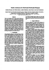
I. I NTRODUCTION The field of service robotics has seen a lot of advances over the last years, but still lacks usability and robustness. We think that one reason for this is the absence of a unifying software architecture that handles the miscellaneous challenges which the software engineers encounter. These challenges vary from the development of distributed applications to the handling of the diversities of different hardware platforms present in service robotics. In this paper we propose a framework that meets these challanges and enables a programmer to develop advanced applications for service robots. A main feature of the framework is the ability to integrate existing solutions to specific robotic problems. We will show that it is possible to encapsulate libraries for motion control for manipulators as well as for mobile robots. A variety of hardware devices connected to the service robot will be integrated into the architecture. A layer of abstraction will generalize the access to these devices. Thus, developed applications can be transferred to other robotic systems without changes. The proposed approach is applied to the service robot of the TAMS Institute at the University of Hamburg. The TAMSService-Robot (TASER) is built from standard components. It is a mobile robot with two manipulators and a multi-modal man-machine interface. Figure 1 shows TASER. The robot operates during normal workdays in an office environment. It
Fig. 1. TASER, the mobile service robot of the Institute TAMS at the University of Hamburg.
is used as an experimental platform to point out the usability of the proposed approach. The remainder of this paper is organised as follows: In section II an overview of existing software architectures in robotics is given. Section III gives a description of the hardware of TASER and shows how the resulting problems occur in service robotics in general. The next section introduces the software architecture and how the hardware is encapsulated by the proposed framework. In Section V some preliminary experimental applications with our robot are presented. Section VI gives a conclusion and an outlook on future work. II. R ELATED R ESEARCH This section gives an overview of existing software architectures for service robots. Recently, a workshop during the 2004 conference on Intelligent Robots and Systems (IROS) tried to list the various research activities in the field of robotic middleware [1]. In the following, some of these activities are discussed. Besides, further related research projects are stated.
The OROCOS project started in 2000 as a free software project due to the lack of reliable commercial robot control software [2]. It is devided into two decoupled sub-projects: Open Realtime Control Services and Open Robot Control Software. The first one is a real-time software framework for applications for machine control. The second one is a set of libraries and an application framework including generic functionality mainly for manipulators. Support of mobile robots is still in its early stages. In 2004 the Orca project emerged from the OROCOS project [3]. It adopts a component-based software engeneering approch using Ice1 for communication and the description of interfaces. The project’s goals are to enable and to simplify software reuse and to provide a generic repository of components. The use of different middleware packages for inter-component communicaton is extensivly discussed on the project’s home page.2 Beside writing custom middleware, the use of CORBA and XML-based technologies is compared to Ice. Orca is available for various operating systems and compiles natively. [4] introduces the Player/Stage project, a client-server framework to enable research in robot and sensor systems. It provides a network interface to a variety of robot and sensor hardware and to multi-robot simulators. Multiple concurrent client connections to the servers are allowed. Client applications connect over TCP sockets. The project’s server software and the simulators are limited to unix-like operating systems. In [5] MARIE is presented, a design tool for mobile and autonomous robot applications. It is mainly implemented in C++ and it uses the ADAPTIVE Communication Environment (ACE)3 for communication and process management. In 2002 Evolution Robotics introduced the Evolution Robotics Software Platform (ERSP) for mobile robots [6]. It is a behaviour-based, modular and extensible software available for Linux and Windows systems. The main components that are included are vision, navigation and interaction. In [7] a service robot for a biotechnological pilot laboratory is presented. The mobile platform of this robot is equal to parts of TASER which is presented in this paper. A seven degreesof-freedom arm is mounted on top of the mobile platform. The system is designed to take samples from a sampling device, handle a centrifuge, a fridge and other biotechnological equipment and fullfil the complete process of sample management. It releaves the personel of the laboratory of monotonous time consuming tasks. Nevertheless it operates in a standard laboratory with standard equipment. An easy-to-use script language is proposed to define high-level work sequences. The scripts are parsed by the robot’s control software and the robot fullfils the defined task. This encourages the idea of simplifying the programming of robots but lacks the flexibility of a widespread programming language including network programming for distributed systems. 1 http://www.zeroc.com 2 http://orca-robotics.sourceforge.net 3 http://www.cs.wustl.edu/∼schmidt/ACE.html
III. ROBOT-H ARDWARE FOR M ULTI -M ODAL I NTERACTION AND S ERVICE TASKS A lot of service robots which are described in literature have in common that they are built from special hardware. Partly, the hardware is designed for certain robot systems only. One of the particular objectives of the robot TASER introduced in this paper is to assemble it mainly from off-the-shelf hardware. This guarantees that most of the solutions developed for this robot can be transferred to other systems. Two further advantages are that damaged parts are easily exchangeable and for most parts of the hardware already existing programs and libraries are used. The main hardware parts of the system are: • • • • • • •
a mobile base including the power supply4 , two robot arms with six degrees of freedom, two three-finger robotic hands for manipulation, a stereo vision system including a pan-tilt unit, an omnidirectional vision system, a monitor with loudspeakers for interaction and one Pentium IV computer for control.
The onboard computer contains additional interface hardware, such as: a high-speed serial interface, an ARCNET interface, a CAN interface, a frame grabber and a wireess network adapter. As operating system of the computer a standard Linux derivate is used. The software architecture introduced in section IV will encapsulate the different components of TASER’s hardware. Therefore, these components are analysed in detail in the following subsections. Their prerequisites, limitations and particularities constitute the foundations of many design decisions for the software architecture. They are presented here since they examplarily show difficulties which are found similarly met by other service robotic platforms. A. Mobile Platform The mobile platform of TASER is a modified MP-L-655 from NEOBOTIX5 with a special extension to mount two robot arms. The platform is equipped with a differential drive with integrated wheel encoders, two laser-range finders and a gyroscope for navigation. The parts are accessed via a Controller Area Network (CAN). The mobile platform is controlled by a C/C++ application developed in [7] and enhanced for TASER. It provides a TCP/IP interface to trigger motion commands. Motion commands allow savely moving the robot forward or backward over a given distance and to rotate the robot to a given orientation. Additionally, pose information from the localization algorithm or measurements from the sensors can be requested. The localization algorithm incorporates an extended Kalman filter and reaches an accuracy of ±1 cm in position and ±1 in orientation. 4 The service robot is powered by eight lead-acid batteries which supply a main power of 48 V olts with the total power of 3.84 kW h. This guarantees an overall independent working time of approximately eight hours. 5 www.neobotix.de
B. Manipulator System The manipulator system of TASER currently consists of two Mitsubishi Heavy Industries PA10-6C robot arms. A BH-262 BarrettHand is attached as a tool to each arm. With this design the system attains a humanlike workspace and silhouette. The PA10-6C has six degrees of freedom (DoF) and a kinematic length which is similar to the length of a human arm. The manipulator is capable of carrying a payload up to 10 kg although its weight is only about 38 kg 6 . It is accessed through an ARCNET interface and controlled by the Robot Control C Libraray (RCCL). RCCL was developed by [8]. [7] extendend RCCL to control the PA10 robot series. The BarretHand is a three-finger robot hand with 8 DoF. The inner joints of each finger are coupled to the outer by a TorqueSwitchTM similar to a human hand [9]. Two fingers are linked by a spread joint. A serial interface and the controllers for the four motors are integrated in the housing of the hand. A self-programmed C++-class library controls the BarrettHand. A real-time control cycle is integrated in the library to make the input from the force sensors of the hand available to other applications. Another self-programmed library encapsulates the arm control and the BarrettHand control. It allows a coupling of the force-sensor measurements of the hand with the arm control. This way, the arm motions can be force-controlled and supervised. The library provides high-level access to the manipulator system. High-level functionality includes cartesian motions of the manipulators and a series of different grasps with the hands. Figure 2 illustrates two of the available grasps. Additionally, some predefined complex motions and work sequences are available. A micro-head camera is mounted on each palm of the BarrettHand. The camera is used as an input device for visual servoing, to fine-position the arm and hand when operations are performed. C. Interaction The Robot is equipped with a versatile multimodal interface for human-robot interaction which uses video, audio and laser range data gathered by the robots active vision system, omnidirectional cameras, microphones and laser-range finders. The passive setup does not interfere with the environment besides the robot itself. There is no need for special hardware that is cumbersome to setup and use like data gloves or magnetic field sensors. The interface is intended to make the interaction between the robot and humans simpler and more intuitive. The main sensors for the interaction are several camera systems mounted on the robot. Beside the micro-head cameras on the hands, the system has a stereo-camera system mounted on a pan-tilt unit. The third vision system of the robot is an IEEE1394-camera that is combined with an hyperboloidal mirror. This combination forms the omnidirectional vision system. 6 This is the weight when running the arm at a power of 100 V olts. We use 48 V olts so the payload might be less than 10 kg
(a)
(b)
Fig. 2. The images show different grasps that can be accomplished by the BarretHand. These grasp are available as high-level functions through the library encapsulating the control software of the BarretHand.
IV. S OFTWARE A RCHITECTURE In the previous section we introduced some of the capabilities of TASER’s different subsystems. In this section we propose a novel software architecture to ease the development of high-level programs combining the functionality of robotic subsystems. A. Roblets The basics of the proposed framework are realised with Java and use Roblet-Technology, a concept firstly introduced in [10]. Roblet-Technology is a client-server architecture where clients can send parts of themselves, referred to as Roblets, to a server. The server, referred to as Roblet-server, then executes the Roblets with well-defined behavior in case of malfunctions. Notice that not only data is transmitted between the client and server but complete executable programs. This can be compared to Java Applets but with the difference that Roblets are not downloaded but sent. Complex setups can consist of multiple client applications and Roblet-servers. A Roblet terminates if the execution of its code finishes normally or throws an exception. Exceptions are sent back to the client application. In addition, a Roblet can be terminated by a client application remotely or by the Roblet-server directly. After a Roblet terminates, the Roblet-server resets itself to a well defined state. Roblet-Technology is applicable to all kinds of distributed systems but it has several features that make its integration into robotic applications useful. In general, high-level applications in service robotics are mostly distributed systems. Besides one or multiple mobile robots, there are visualisation- and control applicatons that run on workstations in a local area network. Sometimes there is no direct access to the robot systems via keyboard, mouse and monitor but only through a wireless network. Roblet-Technology introduces the possibility to develop, compile and execute an application on one workstation. When the application is executed it will send parts of itself to available servers and spread in the local network. Roblets may
Fig. 3. The software architecture of the presented robotic system: Roblet-servers (RS) are used to provide a hardware abstraction layer. Generalization is realized by this hardware abstraction. Distributed applications are independent of the particular hardware of the robot system. Some Roblet-servers and connections are left out for clarity.
send parts of themselves to other servers as well. The network communication is hidden from the programmer by the Roblet library, which simplifies the overall development. That means, the network is transparent and developing distributed applications based on Roblet-Technology is like developing one application for one workstation. Access to the remote servers is encapsulated in a client library, reducing the execution of a Roblet on the remote system to one method call. B. Modules For robotic applications we propose modules to extend the basic Roblet-server provided by the Roblet framework. A module is loaded when the Roblet server is started. It is meant to encapsulate a class of similar functionality. For the robot TASER we developed several modules: One module merges the functionality of the mobile platform, a second module wraps the manipulator system including the robot arms and the hands. There are modules for the different vision systems, the pan-tilt unit, a speech module and other parts of the interaction subsystem. Figure 3 gives an overview of the main parts of the current software architecture for TASER. The system incorporates several smaller Roblet-servers and multiple client applications not shown in the figure for clarity. Notice that the map server and the pathplanning server don’t run on the robot’s control computer but on a workstation in the local network. This allows the integration of information gathered by multiple robots. For example, in the case of dynamic map adjustment this relieves the robot’s onboard computer of some computationally expensive tasks which need no real-time capabilities.
C. Units Modules are further devided in units. Units are Java interfaces that are implemented within the modules. Units build the hardware abstraction layer in our framework. For example, a module encapsulates the localization subsystem of a mobile robot and a Roblet wants to query the current pose estimate7 of the robot. Then the module would implement a unit which defines a method to get the pose. On another robot there may be another localization system encapsulated by another module. But, if the module implements the same unit, the same roblet can be executed on both robots and works without changes. Nonetheless, special features of a subsystem are made available to Roblets if module-specific units, e.g. to change special parameters of a subsystem, are implemented. Therefore a roblet has only access to units, it does not know anything about a module and a module’s implementation of the interface. The whole concept is strictly object-oriented. By introducing units, the framework is able to generalize access to similar classes of subsystems without loosing access to their special features. Additionally, units introduce a possibility of versioning into the system. If new features are integrated into a module then new units will be introduced. As long as older units are still available, all client applications and their Roblets using these old units still work. This has proven to be of great use since complex applications often consist of dozens of client applications and Roblet-servers. A transition to new units can be accomplished step by step for each client application. Figure 4 shows a chart of the structure of a Roblet-server. 7A
pose is the triple of 2D position coordinates and the robot’s orientation.
V. A PPLICATIONS IN S ERVICE ROBOTICS
Fig. 4. The chart shows the structure of a Roblet-server and how it hides the hardware from a Roblet.
D. Platform Independence There were several reasons to use Java to implement the concept of Roblet-Technologie: First of all, Java virtual machines and compilers are available for a variaty of different platforms from embedded system over PDAs to workstation computers. All these different systems can be found in the field of robotics. Since Java source code is compiled into bytecode, the programs can be compiled on any of these systems and executed on another system without change. Besides, Java provides a vast standard library available on all of these systems. The standard libraries include techniques for network communication like RMI or Jini used within the Roblet framework. These well-tested libraries ensure reliable operation of the framework since they are used in millions of internet applications as well. In contrast, using other programming languages like C/C++ would require the compilation of the source code for each target machine. Additional libraries, e.g. CORBA, Ice or ACE, are required for network communication, which demand additional knowledge of the programmer. Further on, these libraries may sometimes be only available for a subset of systems present in a robotic scenario. In future, the .NET framework from Microsoft may become an alternative to Java since it also compiles source code into a bytecode first. Nontheless, to date .NET is only available for Windows platforms. The open-source projects implementing .NET for other platforms do not provide full support yet. Since Java has no real-time capabilities, programs written within a Roblet are not intended to contain real-time control loops. There exists a specification for a real-time java virtual machine but at present no implementation [11]. The Roblet framework allows less skilled programmers to design and develop robotic applications without in-depth knowledge about the used subsystems. First experiences using the Roblet framework in lectures for graduate students have proved this.
In this section we will describe two preliminary experimental applications which emphazise the capabilities of the proposed architecture. The applications control TASER when it accomplishes high-level tasks using a combination of its various components. The first example is a combination of localization, planning of paths, object manipulation and interaction where the robot is instructed to operate a light switch. An operator chooses a light switch and commands the robot via speech commands or an interactive dialog to operate it. The application uses various Roblet-servers shown in figure 3. First, a Roblet on the Roblet-server for the speech IO informs the client application that a light switch is to be operated by the robot. Then the position of the light switch which is stored as a point of interest in a map is requested from a map server. This Roblet-server encapsulates a database in which map elements like obstacles and points of interest are stored. Multiple applications can get, alter or add map elements of the database concurrently through this Robletserver. Then, a Roblet is sent to the pathplanning server to get a path to the light switch. The Roblet sends a new Roblet to the robot. There, the new one drives the robot to a suitable position at the light switch, so that the arm can reach the switch. The position of the arm relative to the switch is obtained form a method call to the arm-operations library which is provided by the corresponding Roblet-server. By solving the kinematic chain, the robot computes a position and orientation suitable to operate the switch. After this position has been reached by the robot arm, a Roblet tries to fine-position the manipulator in front of the light switch with the hand camera by visual servoing. A seperate Roblet-server for the hand camera provides positioning errors calculated on the observed images. When the arm is centered in front of the switch, an approach move is made by the arm which is force controlled by sensor input of the BarrettHand. The sensors of the hand are precise enough to stop the movement of the arm when the finger touches the switch. In the final step the finger operates the switch. By using a final movement of the finger, even switches like the double-switch shown in figure 5(a) can be operated independently. The second example is given by the task of object grasping and transport. The user can advise the robot to fetch and carry objects lying on a table via an interactive dialog. Each source of information about humans interacting with the robot is encapsulated into its own Roblet-server and can thereby be employed by Roblets. The robot plans its path to the object using the Roblet-server for pathplanning. After reaching a position suitable for object grasping, the robot tries to identify the object by means of object recognition. In case of ambiguities the interaction system is used with other Robletservers to resolve the situation. For example, if the robot cannot distinguish objects on the table, it uses the active vision system to recognize pointing gestures and gaze to resolve the position the manipulator of the robot is intended to move to.
R EFERENCES
(a)
(b)
Fig. 5. Left: TASER is operating a double-switch. RIght: TASER is instructed to graps a cup by speech and gesture.
Such a situation is shown in figure 5(b). Additionally, the user can teach the robot new grasping motions and grasps [12]. When the object is successfully recognised, the robot selects a suitable grasp for the object from an internal grasp database and executes it. After grasping the object the robot moves the manipulator back into a safe transporting position. If the transport position has influence on the security outline around the robot, this outline is modified and a path to where the object is to be placed will be calulated based on the new outline. When the final position has been reached the robot will set down the grasped object and is available for new tasks again. Both examples incorporate serveral different Roblets. In both cases the programmer only had to concentrate on the overall work sequence, a still not trivial task. The complex control of the individual actions accomplished by the service robot were only triggered through the various Roblet-servers. The subsystems hidden by the servers executed the control autonomously. Therefore, the Roblet framework introduces a seperation in the development of service robotic applications. On the one hand, there are close-to-hardware programmers providing high-level functionality through Roblet-servers. On the other hand, there are task-oriented programmers using multiple Roblet-server to create complex distributed applications for service robotics. VI. C ONCLUSION The presented software architecture reveals a possibility to build high-level applications for service robots using standard components of the robot as well as specialized hardware. The software architechture of the robot based upon the RobletTechnologie is a powerful medium for robots. The feature of running client programs as a distributed software offers the possibility to run algorithms which need great computation power on different machines which provide this power. The next step will be to implement further software to improve the usability of the robot system and create a toolbox of reusable program parts. In this step the variety of the highlevel functions like object grasping and multimodal interaction will be increased. First results for this are shown in [12]. Furthermore, the possibilities of autonomous navigation and map building will be extended.
[1] Workshop on Robot Middleware towards Standards, International Conference on Intelligent Robots and System (IROS’04), Sendai, Japan, 2004, http://www.is.aist.go.jp/rt/events/20040928IROS.html. [2] H. Bruyninckx: Open robot control software: the OROCOS project, Procedings of the IEEE 2001 International Conference on Robotics and Automation (ICRA’01), volume 3, pages 2523–28, Seoul, Korea, 2001, http://www.orocos.org. [3] A. Brooks, T. Kaupp, A. Makarenko, A. Oreb¨ack, S. Williams: Towards Comonent-Based Robotics, Proceedings ot the 2005 IEEE/RSJ International Conference on Intellegent Robots and Systems (IROS’05), Alberta, Canada, 2005. [4] B.P. Gerkey, R.T. Vaughn, K. Stoy, A. Howard, G.S. Sukhatme, M.J. Mataric: Most Vauable Player: A Robot Device Server for Distributed Control, Proceedings of the IEEE/RSJ International Conference on Intelligent Robots and Systems (IROS’01), pages 1226–1231, Wailea, Hawaii, 2001. [5] C. Cote, D. Letourneau, F. Michaud, J.-M. Valin, Y. Brousseau, C. Raievsky, M. Lemay, V. Tran: Code Reusability Tools for Programming Mobile Robots, Proceedings of the 2004 IEEE/RSJ International Conference on Intellige Robots and Systems (IROS’04), pages 1820–1825, Senda, Japan, 2004. [6] N. Karlsson, M.E. Munich, L. Goncalves, J. Ostrowski, E. Di Bernado, P. Pirjanian: Core Tehnologies for service Robotics, Proceedings of the 2004 IEEE/RSJ Internatiol Conference on Intelligent Robots and Systems (IROS’04), Senda, Japan, 2004. [7] T. Scherer: A mobile service robot for automisation of sample taking and sample management in a biotechnological pilot laboratory, University of Bielefeld, Ph.D Thesis, 2005, http://bieson.ub.unibielefeld.de/volltexte/2005/775/. [8] V. Hayward, J. Lloyd: RCCL User’s Guide, McGill University, Montre’al, Qu’ebec, Canada, 1984. [9] W.T. Townsend: The BarretHand Grasper - programmably flexible part handling and assembly, Industral Robot: An international Journal, Vol. 27, Nr. 3, pp.181-188, 2000. [10] D. Westhoff, H. Stanek, T. Scherer, J. Zhang, A. Knoll: A flexible framwork for task-oriented programming of service robots, Robotik 2004, VDI/VDE-Gesellschaft Mess- und Automatisierungstechnik, VDIBerichte (ISBN 3-18-091841-1), Munich, Germany, 2004. [11] The Real-Time JavaTM Expert Group: The Real-Time Specification for Java (RTSJ), 2002, http://rtsj.dev.java.net. [12] M. H¨user, T. Baier, J. Zhang: Learning of demonstared Grasping Skills by stereoscopic tracking of human hand configuration, To Appear, IEEE International Conference on Robotics and Automation, Orlando, Florida, May 2006.