F. Benrekia et al. / International Journal of Engineering Science and Technology Vol. 2(5), 2010, 1433-1440
A Floating Point Multiplier based FPGA Synthesis for Neural Networks Enhancement F. BENREKIA*1,2, M. ATTARI1 1
LINS: Laboratory of Instrumentation, Faculty of Electronics and Computers, USTHB, BP.32, Bab Ezzouar, 16111, Algiers, Algeria 2
Department of Electronic Engineering, Faculty of Science and Technology, Médéa, 26000, Algeria
[email protected],
[email protected]
Abstract FPGA (Field Programmable Gate Array) implementation of Artificial Neural Networks (ANNs) calls for multipliers of various word lengths. In this paper, a new approach for designing a FloatingPoint Multiplier (FPM) is developed and tested using VHDL. With VHDL (Very High Description Language) analyzer and logic synthesis software, hardware prototypes could be implemented in FPGA. Keywords: Floating-point multiplier, artificial neural networks, VHDL, FPGA implementation. I. Introduction Recently, several applications have been implemented with FPGA using ANNs architecture [1],[2]. These implementations have achieved very good speeds through the use of finite precision arithmetic. An extensive error analysis of finite precision arithmetic has been carried out by Holt and Hwang [3]. Their results show that the number of bits required for representing different parameters like weights, biases, activation, inputs and outputs depend on the algorithm used. For example, while 13 to 16 bits are required for representing weights for back propagation learning, 7 to 8 bits are sufficient for forward retrieving. By taking these results into account, FPGA implementations can keep the system cost low while achieving the best speed performance. For implementing finite precision hardware, it is preferable to design arithmetic units such as adders and multipliers with various word lengths. The recent introduction of X-BLOX design tools [4] is a step in this direction which synthesizes efficient adders, comparators, accumulators, and do not generate multipliers. In order to respond to this later, the proposed work aims to implement Floating-Point Multiplier (FPM) hardware with VHDL. VHDL is the name of the IEEE 1164 hardware description language standard for very high speed digital circuit design. The logic synthesis tool Synopsis is used to synthesize and perform the design into logic gates and gate level simulation for the evaluating the design. II. Floating- point format A simple representation of FP (or real) number (N) uses a binary fraction (F) and exponent (E) [5], where:
N F 2E
(1)
Negative fractions and exponents are represented with two's complement format. In a typical floating-point number system, F is 16 to 64 bits long and E is 8 to 15 bits. In order to keep the example in this paper simple and easy to follows, a 4-bit fraction and a 4-bit exponent will be used. The bit representation of this format is illustrated in Figure1.
MSB
S
E
F
1
8
23
LSB Figure1: IEEE standard 754-1985 format
ISSN: 0975-5462
1433
F. Benrekia et al. / International Journal of Engineering Science and Technology Vol. 2(5), 2010, 1433-1440 In order to utilize all the bits in F and have the maximum number of significant figures, F should be normalized so that its magnitude is larger as possible. If F is not normalized, F could be normalized by shifting it left until the sign bit and the next bit are different. Shifting F left is equivalent to multiplying by 2, so every time shifting, E must be decremented by 1 to keep N the same. After normalization, the magnitude of F will be as large as possible, since any further shifting would change the sign bit. Zero cannot be normalized, so F 0.000 when N 0 and then, any exponent could be used. However, it is best to have a uniform representation of the zero. We will associate the negative exponent with the largest magnitude with the fraction 0. In a 4-bit two's complement integer system, the most negative number is 1000 , which represents -8. Thus, when F and E are 4 bits, 0 is represented by
F 0.000 , E 1000 or 0.000 2 8 . It is obvious, since the smallest non-zero positive number that could be represented is 0.001 2 . Some floating-point systems use a biased exponent, so E 0 is associated with F 0 . IEEE has established a standard for floating-point numbers that provides, a uniform way of storing FP numbers in computer systems [6]. However, most FP arithmetic units convert the IEEE notation to two's complement and then use the two's complement internally for carrying out the FP operations. Then the final result is converted back to IEEE standard notation. -8
III. Floating point multiplication In this section a multiplier for FP numbers is designed. 4-bits fractions and 4-bits exponents are used with negative numbers represented in two's complement. Given two FP numbers, the product
F 2 F E1
1
2
2 E2 F1 F2 2 E1 E2 F 2 E
(2)
The fraction part of the product is the product of the fractions, and the exponent part of the product is the sum of the exponents. We assume that F1 and F2 are properly normalized to start with, and we need the final result to be normalized. Basically, all we have to do is to multiply the fractions and add the exponents. However, several special cases must be considered. First, if F is 0, we must set the exponent E to the largest negative value 1000 . Second, if we multiply -1 by -1 1.000 1.000 , the result should be +1. Since we cannot represent +1 as a two's complement fraction, we call this special case a fraction overflow. To correct this situation, we set multiply the
F 1/ 2 0.100 and add 1 to E. This is justified, since 1 2 E 1 / 2 2 E 1 . When we fractions,
the
0.12 0.12 0.012 E1
E2
E1 E2
result
0.12
could
be
unnormalized.
For
example:
E1E2 1
. In this example, the result is normalized by shifting the fraction left one place and subtracting 1 from the exponent to compensate. Finally, if the resulting exponent is too large in magnitude to represent it in our number system, we have an exponent overflow. Since we are using 4-bits exponents, if the exponent is not in the range 1000 to 0111 (-8 to +7), an overflow has occurred. Since an exponent overflow cannot be corrected, an overflow indicator should be turned on. Figure 2 shows a flowchart for the FPM. After the fraction multiplying is completed, all the special cases must be tested for this purpose. Since F1 and F2 are normalized, the smallest possible magnitude for the product is 0.01. Therefore, only one left shift is required to normalize F.
ISSN: 0975-5462
1434
F. Benrekia et al. / International Journal of Engineering Science and Technology Vol. 2(5), 2010, 1433-1440
Figure 2: Flowchart for floating-point multiplication
IV. Hardware implementation The hardware required to implement the multiplier (Figure 3) consists of main controller (a), an exponent adder (b) and a fraction multiplier (c) [7]. Since we are multiplying 3 bits plus sign by 3 bits plus sign, the result will be 6 bits plus sign. After the fraction multiply, the 7-bit result (F) will be the lower 3 bits of A concatenated with B . When the exponent is added, an overflow can occur. If E1 and E2 are positive and the sum (E) is negative, or if E1 and E2 are negative and the sum is positive, the result is a two's complement overflow. However, this overflow might be corrected when 1 is added to or subtracted from E during normalization or correction of fraction overflow. To allow for this case, we have made the X register 5 bits long. When E1 is loaded into X, the sign bit must be extended so that we have a correct two's complement representation. Since there are two sign bits, if the addition of E1 and E2 produces an overflow, the lower sign bit will get changed, but the higher-order bit will be unchanged.
ISSN: 0975-5462
1435
F. Benrekia et al. / International Journal of Engineering Science and Technology Vol. 2(5), 2010, 1433-1440
(a) Main controller
(b) Exponent adder
(c) Fraction multiplier Figure 3: Exponent adder and fraction multiplier with a main controller
ISSN: 0975-5462
1436
F. Benrekia et al. / International Journal of Engineering Science and Technology Vol. 2(5), 2010, 1433-1440 The SM chart for the main controller (Figure 4) of the floating-point multiplier is based on the flowchart. The controller for the multiplier is a separate state machine, which is linked into the main controller. The SM chart uses the following inputs and control signals, St: Mdone: FZ: FV: Fnorm: EV: Load:
Start the floating-point multiplication. Fraction multiply is done. Fraction is zero. Fraction overflow. F is normalized. Exponent overflow. Load F1, E1, F2, E2 into the appropriate registers (also clear A in preparation for multiplication). Adx: Add exponents; this signal also starts the fraction multiplier. SM8: Set exponent to minus 8. RSF: Shift fraction right; also increment E. LSF: Shift fraction left; also decrement E. V: Overflow indicator. Done: FPM is complete. The SM chart for the main controller has four states. In S0, the registers are loaded when the start signal is 1. In S1, the exponents are added, and fraction multiply is started. In S2, we wait until the fraction multiply is done and then test for special cases and take appropriate action. It may seem surprising that the test on FZ, FV, and Fnorm can all be done in the same state, since they are done in sequence on the flowchart. However, FZ, FV, and Fnorm are generated by combinational circuits that operate in parallel and hence can be tested in the same state. However, we must wait until the exponent has been incremented or decremented at the next clock before we can check for exponent overflow in S3. In S3, the done signal is turned on and the controller waits for St = 0 before returning to S0.
Figure 4: SM chart for floating-point multiplication
ISSN: 0975-5462
1437
F. Benrekia et al. / International Journal of Engineering Science and Technology Vol. 2(5), 2010, 1433-1440 V. FPGA implementation Before synthesis, simulation for the VHDL code is required until the FPM meets the functional specifications. At this level, the VHDL code uses three processes [8], [9]: The main process generates control signals based on the SM Chart. A second process generates the control signals for the fraction multiplier. The third process tests the control signals and updates the appropriate registers on the rising edge of the clock. Testing the VHDL code for the FPM must be done carefully to account for all the special cases in combination with positive and negative fractions, as well as positive and negative exponents. Figure 5a shows a command file (a) and some test results (b) and a functional Simulation (c). list f x f1 e1
f2 e2 v done
force f1 0111 0, 1001 200, 1000 400, 0000 600, 0111 800 force e1 0001 0, 1001 200, 0111 400, 1000 600, 0111 800 force f2 0111 0, 1001 200, 1000 400, 0000 600, 1001 800 force e2 1000 0, 0001 200, 1001 400, 1000 600, 0001 800 force st 1 0, 0 20, 1 200, 0 220, 1 400, 0 420, 1 600, 0 620, 1 800, 0 820 force clk 0 0, 1 10 - repeat 20 run 1000 (a) Stimulus file ps f
x
f1
0 0000000 00000 0 0000000 00000 30 0000000 00001 50 0000000 11001 170 0110001 11001 170 0000000 11001 210 0000000 11001 250 0000000 11010 1 = 0.110001x2-6 170 0000000 11001 410 0000000 11010 430 0000000 00111 450 0000000 00000 570 0100000 00001 170 0000000 11001 610 0000000 00001 630 0000000 11000 650 0000000 10000 770 0000000 11000 790 0000000 11000 800 0000000 11000 830 0000000 00111 850 0000000 01000 970 1001111 01000 990 1001111 01000
e1
0000 0111 0111 0111 0111 0111 1001 1001
f2
e2
v done
0000 0001 0001 0001 0001 0001 1001 1001
0000 0111 0111 0111 0111 0111 1001 1001
0000 1000 1000 1000 1000 1000 0001 0001
0 0 0 0 (0.111x21)(0.111x2-8) 0 0 0 0 0 1 = 0.110001x2-7 0 0 0 0 (1.001x2-7)(1.001x21) 0 0 370 0110001 11010 1001 1001 1001 0001 0
0111 0001 1000 0111 1000 0111 1000 0111 1000 0111 0111 0001 0000 1000 0000 1000 0000 1000 0000 1000 0000 1000 0111 0111 0111 0111 0111 0111 0111 0111 0111 0111
0111 1000 1000 1000 1000 0111 0000 0000 0000 0000 0000 1001 1001 1001 1001 1001
1000 1001 1001 1001 1001 1000 1000 1000 1000 1000 1000 0001 0001 0001 0001 0001
0 0 0 0 0 0 0 0 0 0 0 0 0 0 1 0
0 0 (1.000x27)(1.000x2-7) 0 0 1 = 0.100000x21 0 0(0.000x2-8)(0.000x2-8) 0 0 1 = 0.000000x2-8 0 0 (0.111x27)(1.001x21) 0 0 1 = 1.001111x28 ( overflow ) 0
(b) Test data
ISSN: 0975-5462
1438
F. Benrekia et al. / International Journal of Engineering Science and Technology Vol. 2(5), 2010, 1433-1440
(c) Functional simulation Figure 5a: Stimulus file, Test data and Functional simulation results for FP multiply using Modelsim
After the VHDL code has been thoroughly tested and synthesized (Figure 5b), we complete the logic design and then implement the multiplier using a programmable gate array. The design was placed and routed using the XACT software package from Xilinx using the xc4020E FPGA as the target. The following results indicate the utilization of the device [10], [11], [12], [13]:
Number of External IOBs: 27 out of 224 16% Flops: 17 Latches: 0 Number of IOBs driving Global Buffers: 1 out of 8 12% Number of CLBs: 50 out of 784
6%
Total CLB Flops: 33 out of 1568
2%
4 input LUTs: 92 out of 1568
5%
3 input LUTs: 15 out of 784
1%
Number of PRI-CLKs: 1 out of 4
25%
Min. period (ns): 20 Max. freq. (MHz): 50 The Score for this design is: 534 The Average Connection Delay for this design is: 3.353 ns (298 MHz) The Maximum Pin Delay is: 15.692 ns (64 MHz) The Average Connection Delay on the 10 Worst Nets is: 9.943 ns (101 MHz).
VI. Conclusion and future work Through this paper, we have presented a successful synthesis, and implementation on FPGA circuit of floatingpoint multiplier with 4-bit for fraction and 4-bit for exponent by using the language VHDL. For economic factors, the final FPM FPGA structure can be mapped in another small FPGA package. Since less than half of the available resources were used on xc4020E, it should be possible to design a floating-point multiplier with an 8-bit fraction and 8-bit exponent using the same part. Our next objective is to include these results, for
ISSN: 0975-5462
1439
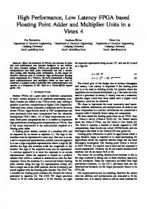
F. Benrekia et al. / International Journal of Engineering Science and Technology Vol. 2(5), 2010, 1433-1440 implementing a multi layer perceptron (MLP) because implementation of artificial neural networks (ANNs) calls for multipliers of various word lengths. E2 [3:0]
Y [3:0] Load V
X [4:3]
done C [3:0]
F1 [3:0]
LSF SM8 Un1 mdone56
Sh
A [3:0] B [3:0]
F [6:0] CL
St Clk
RSF State [2:0] Nextsate Cm Adx
Mul2c mdone 56 Figure 5b: Synthesized output (RTL Netlist) of the FPM using synplify pro.8.1
References [1] [2] [3] [4] [5] [6] [7] [8] [9] [10] [11] [12] [13]
C.E.Cox and W.E.Blanz, "GANGLION- A Fast Field-Programmable Gate Array Implementation of a connectionist Classifier", IEEE Journal of Solid State Circuits, Vol. 27, No. 3, March 1992, pp. 288-299. J.G.Eldredge and B.L.Hutchings, "Density Enhancement of a Neural Network Using FPGAs and Run-Time Reconfiguration", Proc. IEEE workshop on FPGAs for custom Computing Machines, California, 1994. J.L.HOLT and J.N.Hwang, "Finite Precision Error Analysis of a Neural Network Hardware Implementation", IEEE Trans on Computers, Vol. 42, No. 3, March 1993, pp. 164-167. XACT Macro Libraries, Vol. 2: X-BLOX Design tool, Ver 4.1, Dec 1992, Cadence Design Systems, Inc., San Jose, Cali. D. Goldberg, "What every computer scientist should know about floating-point arithmetic ", ACM Computing Surveys, 1991. ANSI/IEEE, New York, IEEE Standard for Binary Floating Point Arithmetic, Std 754-1985 edition, 1985. H. Charles, Jr. Roth, "Digital Systems Design Using VHDL", PWS Publishing Company, 1997. A. Riasmig, FPGA et Outils de développement, Sep.22, 1995, pp.1 à 7. D. Gauthey, E. Messerli, "Conception Numérique:: Description VHDL et Synthèse", Vision, revue scientifique de l'EIVD, 2000. D. Houzet, Conception de circuit en VHDL, Principe et Méthodologie, Cépaduès-edition, 2000. J. Weber, M. Meaudre, VHDL du langage au circuit, du circuit au langage, Masson, 1997. Xilinx, Inc. The Programmable Logic Data Book 1996. (http://www.xilinx.com). http://www.xilinx.com/xapp/xapp467.pdf.
ISSN: 0975-5462
1440