agents motivated from biology can be modelled as X-machines. .... (1995) developed the DESIRE framework, which focuses on the specification of ..... In the following, we will use communicating X-machines to model the collective foraging.
A FORMAL METHOD FOR THE DEVELOPMENT OF AGENT-BASED SYSTEMS P. Kefalas1, M. Holcombe2, G.Eleftherakis1, M.Gheorghe2 1
Dept. of Computer Science, CITY College, 13 Tsimiski Street, Thessaloniki 546 24, Greece Tel. +30310-275575, Fax. +30310-287564 {kefalas, eleftherakis}@city.academic.gr 2 Dept. of Computer Science, University of Sheffield, Regent Court, 211 Portobello Street, Sheffield S1 4DP, UK {m.holcombe, m.gheorghe}@dcs.shef.ac.uk
A FORMAL METHOD FOR THE DEVELOPMENT OF AGENT-BASED SYSTEMS ABSTRACT Recent advances in both the testing and verification of software based on formal specifications of the system to be built have reached a point where the ideas can be applied in a powerful way in the design of agent-based systems. The software engineering research has highlighted a number of important issues: the importance of the type of modelling technique used; the careful design of the model to enable powerful testing techniques to be used; the automated verification of the behavioural properties of the system; the need to provide a mechanism for translating the formal models into executable software in a simple and transparent way. This chapter presents a detailed and comprehensive account of the ways in which some modern software engineering research can be applied to the construction of effective, and reliable agent-based software systems. More specifically, we intend to show how simple agents motivated from biology can be modelled as X-machines. Such modelling will facilitate both verification and testing of an agent model, since appropriate strategies for model checking and testing are already developed around the X-machine method. In addition, modular construction of agent models is feasible since X-machines are provided with communicating features, which allow simple models to interact. INTRODUCTION An agent is an encapsulated computer system that is situated in some environment and that is capable of flexible, autonomous action in that environment in order to meet its design objectives (Jennings, 2000). There are two fundamental concepts associated with any dynamic or reactive system, such as an agent, that is situated in and reacting with some environment (Holcombe & Ipate, 1998): • the environment itself, which could be precisely or ill-specified or even completely unknown, but nevertheless involves identifying the important aspects of the environment and the way in which they may change in accordance with the activities of the agent, • the agent will be responding to environmental changes by changing its basic parameters and possibly affecting the environment as well. Thus, there are two ways in which the agent reacts, i.e. it undergoes internal changes and it produces outputs that affect the environment. Agents, as highly dynamic systems, are concerned with three essential factors: • a set of appropriate environmental stimuli or inputs, • a set of internal states of the agent, and • a rule that relates the two above and determines what the agent state will change to if a particular input arrives while the agent is in a particular state. One of the challenges that emerge in intelligent agent engineering is to develop agent models and agent implementations that are “correct”. According to Holcombe & Ipate (1998), the criteria for “correctness” are: • the initial agent model should match with the requirements, • the agent model should satisfy any necessary properties in order to meet its design objectives, and
•
the implementation should pass all tests constructed using a complete functional test generation method. All the above criteria are closely related to three stages of agent system development, i.e. modelling, verification and testing. Although agent-oriented software engineering aims to manage the inherent complexity of software systems (Wooldridge & Ciancarini, 2001), there is still no evidence to suggest that any methodology proposed leads towards “correct” systems. In the last few decades, there has been a strong debate on whether formal methods can achieve this goal. Academics and practitioners adopted extreme positions either for or against formal methods (Young, 1991). It is, however, apparent that the truth lies somewhere between and that there is a need for use of formal methods in software engineering in general (Clarke & Wing, 1996), while there are several specific cases proving the applicability of formal methods in agent development, as we shall see in the next section. Software system specification has centred on the use of models of data types, either functional or relational models such as Z (Spivey, 1989) or VDM (Jones, 1990) or axiomatic ones such as OBJ (Futatsugi et al., 1985). Although these have led to some considerable advances in software design, they lack the ability to express the dynamics of the system. Also, transforming an implicit formal description into an effective working system is not straightforward. Other formal methods, such as Finite State Machines (Wulf et al., 1981) or Petri Nets (Reisig, 1985) capture the essential feature, which is “change”, but fail to describe the system completely, since there is little or no reference at all to the internal data and how this data is affected by each operation in the state transition diagram. Other methods, like Statecharts (Harel 1987), capture the requirements of dynamic behaviour and modelling of data but are rather informal with respect to clarity and semantics. So far, little attention has been paid in formal methods that could facilitate all crucial stages of “correct” system development, modelling, verification and testing. This chapter will introduce such a formal method, namely X-machines, which closely suits the needs of agent development, while at the same time being intuitive and practical. FORMAL METHODS IN AGENT-BASED SYSTEMS In agent oriented engineering, there have been several attempts to use formal methods, each one focusing on different aspects of agent systems development. One of them was to formalise PRS (Procedural Reasoning System), a variant of the BDI architecture (Rao & Georgeff, 1995) with the use of Z, in order to understand the architecture in a better way, to be able to move to the implementation through refinement of the specification and to be able to develop proof theories for the architecture (D’Iverno et al. 1998). Trying to capture the dynamics of an agent system, Rosenschein & Kaebling (1995) viewed an agent as a situated automaton that generates a mapping from inputs to outputs, mediated by its internal state. Brazier at al. (1995) developed the DESIRE framework, which focuses on the specification of the dynamics of the reasoning and acting behaviour of multi-agent systems. In an attempt to verify whether properties of agent models are true, work has been done on model checking of multi-agent systems with re-use of existing technology and tools (Benerecetti et al. 1999, Rao & Georgeff, 1993). Towards implementation of agent systems, Attoui & Hasbani (1997) focused on program generation of reactive systems through a formal transformation process. A wider approach is taken by Fisher & Wooldridge (1997) who utilise Concurrent METATEM in order to formally specify multi-agent systems and then directly execute the specification while verifying important temporal properties of the system. Finally, in a less
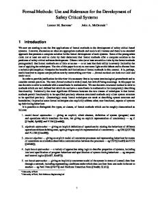
formal approach, extensions to UML to accommodate the distinctive requirements of agents (AUML) were proposed (Odell et al, 2000). In this chapter, we intend to show how simple agents motivated from biology can be modelled as X-machines. Such modelling will facilitate both verification and testing of an agent model, since appropriate strategies for model checking and testing are already developed around the X-machine method. In addition, modular construction of agent models is feasible since Xmachines are provided with communicating features, which allow simple models to interact. Finally, tools developed for X-machines are briefly presented in order to demonstrate the practicality of the approach. X-MACHINE DEFINITION A X-machine is a general computational machine introduced by Eilenberg (1974) and extended by Holcombe (1988) that resembles a Finite State Machine (FSM) but with two significant differences: • there is memory attached to the machine, and • the transitions are not labeled with simple inputs but with functions that operate on inputs and memory values. These differences allow the X-machines to be more expressive and flexible than the FSM. Other machine models like pushdown automata or Turing machines are too low level and hence of little use for specification of real systems. X-machines employ a diagrammatic approach of modelling the control by extending the expressive power of the FSM. They are capable of modelling both the data and the control of a system. Data is held in memory, which is attached to the X-machine. Transitions between states are performed through the application of functions, which are written in a formal notation and model the processing of the data. Functions receive input symbols and memory values, and produce output while modifying the memory values (Fig.1). The machine, depending on the current state of control and the current values of the memory, consumes an input symbol from the input stream and determines the next state, the new memory state and the output symbol, which will be part of the output stream. The formal definition of a deterministic stream X-machine (Ipate & Holcombe, 1998) is an 8-tuple XM = (Σ, Γ, Q, M, Φ, F, q0, m0), where: • Σ, Γ is the input and output finite alphabet respectively, • Q is the finite set of states, • M is the (possibly) infinite set called memory, • Φ is the type of the machine XM, a finite set of partial functions φ that map an input and a memory state to an output and a new memory state, φ:Σ×M→Γ×M • F is the next state partial function that given a state and a function from the type Φ, denotes the next state. F is often described as a state transition diagram, F:Q×Φ→Q • q0 and m0 are the initial state and memory respectively. X-machines can be used as a core method for an integrated formal methodology of developing correct systems.
MEMORY
m
m’ γ
σ
input stream
φ1 φ3
φ2
S1 φ2 S2
φ5
S3
S4
φ2
output stream
φ4
φ4
Fig. 1. An abstract example of a X-machine; φi: functions operating on inputs and memory, Si: states. The general formal of functions is: φ(σ,m) = (γ,m’) if condition
The X-machine integrates both the control and data processing while allowing them to be described separately. The X-machine formal method forms the basis for a specification/modelling language with a great potential value to software engineers. It is rather intuitive, while at the same time formal descriptions of data types and functions can be written in any known mathematical notation. Finally, X-machines can be extended by adding new features to the original model, such as hierarchical decomposition and communication, which will be described later. Such features are particularly interesting in agent-based systems. FORMAL AGENT MODELLING Many biological processes seem to behave like agents, as for example a colony of ants. Much research has been based on such behaviour in order to solve interesting problems (Dorigo & Di Caro, 1999). An important task of some ants is to find food and carry it to their nest. This can be accomplished by searching for food at random or by following pheromone trails that other ants have left on their return back to the nest (Deneubourg et al., 1990). While moving, an ant should avoid obstacles. Once food is found, an ant should leave a pheromone trail while travelling back to its nest, thus implicitly communicating with other ants the destination of a source where food may be found. When the nest is found, the ant drops the food. Clearly, this is a reactive agent that receives inputs from the environment and acts upon these inputs according to the state in which the agent is. Such reactive agents can be fairly easily modelled by a FSM in a rather straightforward way by specifying the states and the inputs (percepts) to be used for state transitions (Fig.2). The FSM lacks the ability to model any non-trivial data structures. In more complex tasks, one can imagine that the actions of the agents will also be determined by the values stored in its memory. For example, an agent may know its position, remember the position of the food source or the position of obstacles, thus building a map of the environment in order to make the task eventually more efficient. Using FSM or variants of it (Brooks 1986, Rosenschein & Kaebling 1995) for such agents is rather complicated since the number of states increases in combinatorial fashion to the possible values of the memory structure. X-machines can facilitate modelling of agents that demand remembering as well as reactiveness. Fig.3 shows the model of an ant that searches for food, but also remembers food positions in order to set up its next goals. The behaviour of obstacle avoidance is omitted for simplicity.
AT NEST pheromone
space
space
nest pheromone
nest space
FOLLOWING TRAIL food pheromone pheromone
MOVING FREELY
pheromone space
LIFTING FOOD
food space
obstacle
obstacle
obstacle
AT OBSTACLE
Fig. 2: A Finite State Machine modelling an ant’s behaviour
ignore food
stay_at_nest
AT NEST move
move_to_food find_nest
LOOKING FOR FOOD
move_to_nest
move_to_food
drop_food GOING BACK TO NEST
move
find_nest find_food
MOVING FREELY
move_to_nest lift_food
AT FOOD
lift_food
got_lost
Fig. 3. A X-machine that models an ant
Formally, the definition of the X-machines requires all elements of the 8-tuple (Σ, Γ, Q, M, Φ, F, q0, m0). First of all, the input set consists of the percept and the x and y coordinate it is perceived: Σ = ({space, nest} ∪ FOOD) × COORD × COORD where [FOOD] is a basic type and COORD is of type integer, COORD⊆Z. The set of outputs is defined as a set of messages: Γ={“moving freely”, “moving to nest”, “dropping food”, …} The states in which the agents can be are five: Q={At Nest, Moving Freely, At Food, Going Back To Nest, Looking For Food}. The state “Moving Freely” applies to an agent that does not have a specific goal and searches in random for a food source. The state “Going Back To Nest” applies when the agent is carrying a food item and it is on its way back to its nest. The state “Looking For Food” applies when the agent has a goal, i.e. remembers where food is found during previous explorations of the terrain. The memory consists of three elements, i.e. what the agent carries, the current position of the agent, and the sequence of positions where food is found during its exploration: M = (FOOD∪{none}) × (COORD × COORD) × seq (COORD × COORD)
where none indicates that no food is carried. The initial memory and the initial states are respectively: m0 = (none, (0,0), nil) q0 = “At Nest” It is assumed that the nest is at position (0,0). The next state partial function is depicted with the state diagram in Fig.3. The type Φ is a set of functions of the form: function_name(input_tuple, memory_tuple) → (output, memory_tuple’), if condition. For example, here are some function definitions: lift_food( (f,x,y),(none,(x,y),foodlist) ) → ("lifting food",(f,(x,y),)), if f∈FOOD ∧ (x,y)∉foodlist find_food( (f,fpx,fpy), (food,(x,y),foodlist) ) → ("more food",(food,(x,y),)), if f∈FOOD ∧ f∉foodlist drop_food( (nest,0,0), (food,(x,y),foodlist) ) → ("dropping food",(none,(0,0),foodlist)) find_nest( (nest,0,0), (none,(x,y),foodlist) ) → ("found nest again",(none,(0,0),foodlist)) VERIFICATION OF AGENT MODELS Having designed a model for an agent, it would be desirable to verify whether it corresponds to the requirements, i.e. at all circumstances during the existence of the agent modelled in some way, its required properties are true in that model. Model checking is a formal verification technique, which determines whether given properties of a system are satisfied by a model. A model checker takes a model and a property as inputs and outputs either a claim that the property is true or a counterexample falsifying the property. In order to use model checking, the most efficient way to express a model is any kind of state machine, a CCS agent, a Petri Net, a CSP agent, etc. The most common properties to check are either something will never occur or something will eventually occur. In Temporal Logic Model Checking (Clarke et al., 1986) a property is expressed as a formula in a certain temporal logic. The verification can be accomplished using an efficient breadth first search procedure, which views the transition system as a model for the logic and determines if the specifications are satisfied by that model. This approach is simple, completely automated but has one major problem, namely the state explosion. The latter can be handled to some extent by a model checking variant, the symbolic model checking (McMillan, 1993). Model checking is sometimes proved to be more efficient than other formal verification techniques, such as theorem proving (Burch et al., 1992). On the other hand, model checking is formal as opposed to simulation, which may reveal inconsistencies and misconceptions in a model, but does not guarantee completeness of the model with respect to requirements. Bearing in mind the most usual definition of a model, i.e. a labelled state transition graph, also called a Kripke structure (Kripke, 1963), model checking utilises algorithms that, given a temporal logic formula, verifies whether properties hold in the model. A Kripke structure is a tuple where: • Q is non-empty set of states, • R is a binary relation on Q, i.e. R⊆Q×Q, which shows which states are related to other states, and • L:Q→2Prop is a truth assignment function that shows which propositions are true in each state, where Prop is a set of atomic propositions.
Temporal logic formulae, e.g. CTL* formulae, are constructed through the use of operators combined with the path quantifiers A (meaning “for all paths”) or E (meaning “there exists a path”). The five basic CTL* operators are (Emerson & Halpern, 1986): • X (next time) requires that a property holds in the next state, • F (eventually) requires a property to hold at some state on a path, • G (always) requires a property to hold at every state on a path, • U (until) requires a property p to hold in a path until another property q holds, • R (release) as a dual operator of U. The above logic could be extended to accommodate past, present and future properties of an agent system, as in FML (Fisher & Wooldridge, 1997). Having constructed a model of an agent as a X-machine, it is possible to apply existing model checking techniques to verify its properties. That would require transformation of a Xmachine into another model that resembles a Kripke structure. Such a process exists, called the exhaustive refinement of a X-machine to a FSM, and results in a model in which CTL* formula may be applied. However, exhaustive refinement suffers two major disadvantages: • the loss of expressiveness that the X-machine possesses, and • the combinatorial explosion. The former has to do with the memory structure attached to X-machine. In an equivalent FSM resulting from the process of refinement, the memory will be implicitly contained in states. It would be therefore impossible to verify that certain properties are true for some memory instances of the states of the original X-machine model, since this information is lost during the refinement process. The latter has to do with properties which are contained in the model’s memory but do not play any role in model checking with respect some other properties. Exhaustive refinement may result in a possibly infinite state space, if such properties are included in the equivalent FSM, thus making model checking impossible. In order to apply model checking in X-machines, temporal logic is extended with memory quantifier operators: • Mx, for all memory instances and • mx, there exist memory instances, which together with the basic temporal operators of CTL*, can form expressions suitable for checking the properties of an agent model. The resulting logic XmCTL can verify the model expressed as X-machine against the requirements, since it can prove that certain properties, which implicitly reside in the memory of X-machine are true (Eleftherakis & Kefalas, 2001). For example, in an agent whose task is to carry food to its nest as in the example of Fig.3, model checking can verify whether eventually food will be dropped in the nest by the formula: AG [ ¬Mx (m1≠none) ∨ EFMx (m1=none) ] where m1 indicates the first element of the memory tuple. The formula states that, in all states of the X-machine, it is true that either the ant does not hold any food or there exists a path after that state where eventually the ant does not hold any food. Another example is the formula: E [Mx (m1=none) U Mx (m1≠none) ] i.e., there exists a path in which the ant eventually holds food and in all previous states the ant holds nothing. Also, another useful property to be checked is: ¬EFmx [ (m1≠none) ∧ (m3=nil) ] i.e., if the ant holds something then the food list is not empty. The new syntax and semantics facilitate model checking of X-machines in two ways: • expressiveness suited to the X-machine model, and
•
effective reduction of the state space through selective refinement of the original Xmachine model.
COMPLETE TESTING OF AGENTS In the previous section, we have focused in modelling of an agent and verification of the models specified with respect to requirements. Having ensured that the model is “correct”, we need to also ensure that the implementation is “correct”, this time with respect to the model. This can be achieved through testing, but only under one important assumption, i.e. testing is complete. To guarantee “correctness” of the implementation, one must be certain that all tests are performed, and the results correspond to what the model has specified. Holcombe & Ipate (1998) presented a testing method, which is a generalisation of Chow’s Wmethod (Chow, 1978) for FSM testing. It is proved that this testing method finds all faults in the implementation (Ipate & Holcombe, 1998). The method works based on the following assumptions: • the specification and the implementation of the system can be represented as X-machines, • the X-machine corresponding to the specification and the X-machine corresponding to the implementation have the same type Φ. Assuming the above, the method also requires that: • the X-machine satisfies the design for test conditions, and • its associated automaton is minimal. The associated automaton of a X-machine is the conversion of the X-machine to a FSM by treating the elements of Φ as abstract input symbols. The design for test conditions states that the type Φ of the two machines is both complete with respect to memory and output distinguishable. A processing function φ∈Φ is called complete with respect to memory if: ∀m∈M, ∃σ∈Σ such that (m, σ)∈dom φ A type Φ is called complete with respect to memory M, if any basic function will be able to process all memory values, that is if: ∀φ∈Φ, φ is complete with respect to M A type Φ is called output distinguishable if any two different processing functions will produce different outputs on each memory/input pair, that is if: ∀φ1,φ2∈Φ if ∃m∈M, σ∈Σ such that for some m1΄,m2΄∈M, γ∈Γ φ1(m, σ) = (γ, m1΄) and φ2(m, σ) = (γ, m2΄), then φ1 = φ2. If Φ is not complete then additional input symbols may be introduced such as to make processing functions complete (Holcombe & Ipate, 1998). In Fig.4, the X-machine illustrates a model of an ant that either looks for food at random or follows the pheromone trail to find food and nest. The input set is Σ={space, nest, pheromone, food}. The X-machine satisfies the design for test conditions and its associated automaton is minimal.
ignore_nest
stay_at_nest move
MOVING FREELY
AT NEST
ignore_food
move
move_to_food found_nest
ignore_space
lift_food
ignore_food
move_to_food
FOLLOW TRAIL
HAVE FOOD
ignore_space
lift_food
move_to_nest
move_to_food
ignore_nest
Fig. 4. An X-machine that satisfies the design for test conditions
When these requirements are met, the W-method may be employed to produce the k-test set X of the associated automaton, where k is the difference of the number of states of the two associated FSMs. The test-set X consists of processing functions for the associated automaton, and it is given by the formula: X = S(Φk+1 ∪ Φk ∪ … ∪ Φ ∪ {ε})W where W is a characterisation set and S a state cover. Informally, a characterisation set W⊆Φ* is a set of processing functions for which any two distinct states of the machine are distinguishable. The state cover S⊆Φ* is a set of processing functions such that all states are reachable by q0. The W and S sets in the agent X-machine in Fig.4 are: W= [stay_at_nest, move move_to_food, found_nest] S= [ε, move, move move_to_food, move_to_food lift_food] The derived test-set X, for k=0, i.e. model and implementation are considered as FSM with the same number of states, is the following: X= {move move move_to_food, move move move move_to_food, move ignore_nest move move_to_food, move lift_food found_nest, move move_to_food lift_food found_nest, move_to_food lift_food found_nest, move_to_food lift_food ignore_space found_nest, …} The fundamental test function is defined recursively, and converts these sequences into sequences of inputs of the X-machine. Let XM = (Σ, Γ, Q, M, Φ, F, q0, m0) be a deterministic stream X-machine with Φ complete with respect to M and let q∈Q, m∈M. A function tq, m: Φ*→ Σ* will be called a test function of M with respect to q and m, will be defined recursively as (Ipate and Holcombe, 1998): tq,m(ε) = or
tq, m(φ1…φnφn+1) =
ε (the empty input symbol) tq, m(φ1φ2…φn) σn+1, if ∃ a path q,q1,…,qn-1,qn, in M starting from q, where σn+1 is such that (mn, σn+1)∈dom φn+1 and mn is the final memory value computed by the machine along the above path on the input sequence tq, m(φ1φ2…φn) tq, m(φ1φ2…φn),otherwise
The test-set containing sequences of inputs for the ant X-machine is the following: {space space pheromone, space space space, pheromone, space nest space pheromone, space food nest, space pheromone food nest, pheromone food nest, pheromone food space nest, …} The test-set so produced is proved to find all faults in the agent implementation. The testing process can therefore be performed automatically by checking whether the output sequences produced by the implementation are identical with the ones expected from the agent model. AGENTS AS AGGREGATION OF BEHAVIOURS Agents can be modelled as a stand-alone (possibly complex) X-machine as shown in the previous section. However, an agent can be also viewed as a set of simpler components, which model various different behaviours of the agent. This fits with the three principles of complex agent systems: decomposition, abstraction, and organisation (Jennings, 2001). Another approach for reactive agents is described in the subsumption architecture (Brooks, 1991), in which behaviours can communicate with each other in order to result in a situated agent with the desired overall robust performance. Similarly, Collinot et al. (1996) developed the Cassiopeia method, in which agents are defined by following three steps: • identifying the elementary behaviours that are implied by the overall task, • identifying the relationship between elementary behaviours, and • identifying the organisational behaviours of the system. A methodology of building communicating X-machines from existing stand-alone X-machine is developed so that modelling can be split into two separate activities: • the modelling of X-machine components, and • the description of the communication between these components. The approach has several advantages for the developer who: • does not need to model a communicating system from scratch, • can re-use existing models, • can consider modelling and communication as two separate distinct activities, and • can use existing tools for both stand-alone and communicating X-machines. Let us discuss the above one by one. Certain approaches for building a communicating system require a brand new conceptualisation and development of a system as a whole. This approach has a major drawback, i.e. one cannot re-use existing models that have been already verified and tested for their “correctness”. Often, in agent systems, components from other agent systems are required. A desirable approach would be to conceptualise the system as a set of independent smaller models, which need to communicate with each other. Thus, one does not need to worry about the individual components, in which model checking techniques and testing are applied, but only with appropriately linking those components. This would lead to a disciplined development methodology, which implies two distinct and largely independent development activities, i.e. building models and employing communication between them. Also, this means that existing languages and tools for modelling, model checking and testing are still useful and can be further extended to support larger communicating systems. Several theoretical approaches for communicating X-machines have been proposed (Balanescu et al. 1999, Cowling et al. 2000, Barnard 1998). In this section we will describe the one that focuses on the practical development of communicating systems but also subsumes all others (Kefalas et al., 2001). In this approach, the functions of a X-machine, if so annotated, read input from a communicating stream instead of the standard input stream. Also, the functions may write to a communicating input stream of another X-machine. The
normal output of the functions is not affected. The annotation used is the solid circle (IN port) and the solid box (OUT port) to indicate that input is read from another component and output is directed to another component respectively. For example, function φ in Fig.5 accepts its input from the model x-m1 and writes its output to model x-m2. Multiple communications channel for a single X-machine may exist. Another example is a simple form of communication between two ants. Assume that one ant is responsible to notify another ant about the position of the food source. In order to achieve communication the X-machines should be modified as illustrated in Fig.6. The function lift_food of the X-machine model ant2 becomes: lift_food( (f,x,y),(none,(x,y),foodlist) ) → (OUTx-m ant2(f,x,y), (f,(x,y),)), if f∈FOOD ∧ (x,y)∉foodlist and the function find_food of X-machine model ant1 becomes: find_food(INx-m ant1 (f,fpx,fpy), (food,(x,y),foodlist) ) → ("more food",(food,(x,y),)), if f∈FOOD ∧ (fpx,fpy)∉foodlist Function find_food of ant2 may be modified accordingly to write a message to the OUT port, if needed. X-machine x-m2 standard
standard
x-m1
input stream
channel for receiving message from x-m1
output stream
φ IN port
OUT port
channel for sending message to x-m2
Fig. 5. An abstract example of a Communicating X-machine component.
The approach is practical, in the sense that the designer can separately model the components of an agent and then describe the way in which these components communicate. This allows a disciplined development of situated agents. Practically, as we shall see later, components can be re-used in other systems, since the only thing that needs to be changed is the communication part. ANT2
ANT1 drop_food
ant2 ant1
GOING BACK TO NEST move_to_nest
MOVING FREELY
move_to_nest find_food
AT FOOD
lift_food
move
move_to_nest
Fig. 6. Ant2 X-machine sends a message about food position in Ant1 X-machine, by utilizing a communicating port.
In the following, we will use communicating X-machines to model the collective foraging behaviour of a colony of honey-bees as it is fully compatible with the rules used by foraging honey-bees (Vries & Biesmeijer, 1998) that include specifications for: • travelling from the nest to the source, • searching for the source, • collecting nectar from the source, • travelling back to the nest,
• transmitting the information about the source (the dancing of the returning bee), • the reaction of a bee in the nest to the dancing of a nest mate. A foraging bee can be modelled according to a set of independent behaviours, which constitute the components of the overall agent. Fig.7 shows some of the behaviours of a foraging bee modeled as simple X-machines, with an input set Σ and a memory tuple M. Each machine has different memory, inputs (percepts), and functions. Some states and functions were on purpose named differently to show the modularity of the approach. It is assumed that the bee perceives: • empty space to fly (space), • the hive (nest), • the source of nectar (source), • an amount of nectar (nectar), • other bees, i.e. foraging bees (fbee) or receiving bees (rbee), and finally • understands when it has lost its orientation (lost). Behaviour Traveling from nest to source: Σ = {space, source} M = (bee_pos, source_pos) q0 = at source
X-machine model fly_to_source find_source
AWAY FROM SOURCE
AT SOURCE keep_flying
keep_flying
Searching for the source: Σ = {space, source} M = (bee_pos, source_pos) q0 = flying
search detect_source
AT NECTAR SOURCE
FLYING fly_back fly_back
Collecting nectar from the source: Σ = {nectar, rbee} M = (nectar_amount) q0 = carrying nothing Traveling back to the nest: Σ = {nest, space} M = (nest_pos) q0 = at hive Transmitting information about the source (dancing): Σ = {fbee, space, nest, source} M = (bee_pos, source_pos) q0 = in the nest Reacting to the information transmitting by the dancing: Σ = {space, lost, source_pos} M = (status, source_pos) q0 = flying freely
collect_nectar
CARRYING NOTHING
CARRYING NECTAR transfer_nectar detect_hive
OUT OF HIVE
AT HIVE fly_out
dancing
find_source fly_out
IN THE NEST
OUT OF NEST fly_in keep_fly_out
fly
loose_source_info get_info_from_dance
FLYING FLEELY
FLYING TO SOURCE fly
ignore_dance
Fig. 7. The behaviours of a foraging bee modeled separately as X-machine components.
The memory of each X-machine holds information on the bee, the source and the nest positions (bee_pos, source_pos and nest_pos), the amount of nectar carried (nectar_amount), and its status (employed or unemployed). For example, consider the X-machine modelling the dancing behaviour. Its functions are defined as follows (Gheorghe et al, 2001): dancing(fbee, (bee_pos, source_pos)) → (“dancing”, (bee_pos, source_pos)) fly_out(space, (bee_pos, source_pos)) → (“flying out”, (bee_pos’, source_pos)) fly_in(nest, (bee_pos, source_pos)) → (“flying in”, (bee_pos’, source_pos)) find_source(source,(bee_pos,source_pos))→(“sourcefound”,(source_pos, source_pos)) keep_fly_out(space,(bee_pos ,source_pos)) → (“keep flying”,(bee_pos’, source_pos)) where bee_pos, bee_pos’, source_pos∈Set_of_positions. The bee position can be calculated by some external function or some other X-machine. Fig.8 shows in detail how communication can be achieved directly by various honey-bees, e.g. an employed foraging bee sends the source position to another foraging bee through the dancing behaviour: dancing(fbee, (bee_pos, source_pos)) → (OUTx-m reacting(source_pos), (bee_pos, source_pos)) while an unemployed foraging bee reads the source position by the function: get_info_from_dance(INx-m dancing(source_pos),(unemployed, nil)) → (“getting source info”, (employed, source_pos)). If the foraging bee is currently employed, it just ignores the message: ignore_dance(INx-m dancing(source_pos),(employed, source_pos)) → (“ignoring source info”, (employed, source_pos)). The same communication takes place when a foraging bee transfers the amount of nectar that is carrying to a receiving bee waiting at the hive. x-m reacting
fly
dancing
find_source fly_out
IN THE NEST
OUT OF NEST fly_in
X-M DANCING
x-m dancing
loose_source_info get_info_from_dance
FLYING FLEELY
FLYING TO SOURCE fly
ignore_dance keep_fly_out
Behaviour of a foraging employed bee
x-m dancing
X-M REACTING
Behaviour of a foraging unemployed bee
Fig. 8. An example of two communicating behaviours; an employed bee sends information about the source position to an unemployed bee.
The separate behaviours can be put together in a communicating X-machine model. Fig.9 shows the complete foraging bee system, which is made up of component X-machines, which communicate via channels. Each machine works separately and concurrently in an asynchronous manner. Each machine can read inputs from a communication channel instead of its standard input tape. Also, each machine can send a message through a communication channel that will act as input to functions of another component. The figure shows an extra component, i.e. the perception system of the bee, which provides percepts to various behaviours.
In addition, more machines can be modelled, as for example, the X-machine that builds an environment map (positions of obstacles, nest, food items etc.). Information held in the memory of this machine could be used to efficiently move around the environment, or even to model a pro-active behaviour for the agent. Thus, modelling of an agent can be incremental by providing components, which will advance further the level of intelligent behaviour. FORAGING BEE
detect_space detect_nest
PERCEPTING
detect_bee
space, source
space, source
traveling from nest to source
searching for source
detect_source
rbee
collecting nectar from source and transferring it
detect_nectar
got_lost
nest, space
traveling back to nest
ubee, space, nest, source
dancing
space, lost
reacting to dancing
Fig.
9. Communicating X-machine modelling agent bee through aggregation of behaviours
The whole system works as follows: an employed bee accepts inputs from the environment, which cause transitions in the X-machine components that model its individual behaviours. Having found a source and after collecting nectar (appropriate transitions have been performed in source and environment X-machines), the bee returns to hive and on the sight of another foraging bee performs the dancing which, as shown earlier, transmits the information of the source position. An unemployed bee accepts the input from its communication port and changes its status to employed. It can then perceive inputs from the environment and travels to the source. The whole process may then be repeated. In parallel, other bees can do the same in an asynchronous manner. The approach is practical, in the sense that the developer can separately model the components of an agent and then describe the way in which these components-behaviours communicate. Also, components can be re-used in other systems, since the only thing that needs to be changed is the communication part. For example, the behaviour for avoiding obstacles is a component of any biology-inspired agent, e.g. foraging bees or ants. The major advantage is that the methodology also lends itself to modular model checking and testing strategies in which X-machines are individually tested as components while communication is tested separately with existing methodologies, mentioned earlier. MULTI-AGENT MODELS Modelling multi-agent systems requires the consideration of the means of communicating between agents, in order to coordinate tasks, cooperate etc. Also, modelling of artificial environments in which agents act imposes the need of exchanging “messages” between agents and the environment. For example, a number of ants modelled as X-machines need to interact with their environment, which contains few seeds (food items) that are also modeled as Xmachines. These two ants, which may be instances of the same model class, can communicate with the environment in order to achieve the desired behaviour, i.e. to lift a heavy seed that is far from the abilities of a single agent (Fig.10). Several behaviours are omitted for the sake of exposition. The ant is capable of lifting a food item only if the strength it possesses is bigger than the weight of a food item. In any other case, cooperation between ants is necessary, which can be achieved by communication of ants and the food item machine. The method
used in the previous section to describe communicating X-machines can also serve this purpose. store
ANT1
AT NEST walk_to_nest
free_walk
free_walk
SEED
find_nest
CARRYING FOOD
lift find_nest continue_free_walk
MOVING FREELY
force_applied found
lift_food
find_food
AT FOOD
found lift
force_applied
ON GROUND attempt_lift
found
BECOME LIGHTER
force_applied force_released
force_released
put_down
ANT2
LIFTED
BECOME HEAVIER found
force_released put_down
Fig. 10. Ants model cooperating in the lifting task through communication with the environment
In addition, one may require agents which resemble one another, i.e. they have a common set of behaviours, but extra individual behaviours which determine some task that characterise their individuality. For example, in a colony of foraging bees, some bees are responsible for collecting nectar from a source as well as have the ability to “inform” others about the location of the source (the dance of the foraging bee) while other bees are responsible for storing the nectar into the hive (Seely & Buhrman, 1999). Nevertheless, all of them have the ability to fly, receive nectar etc. Such situations can be modelled with X-machines, as long as there is a way to define classes of models and instances of these classes, which can inherit generic behaviours from the chain of hierarchy. Fig.11 demonstrates the whole multi-agent system that models the colony of the honey bees as well as the environment and its various components, such as the source and the nest. The same happens when coordination is achieved by some other agent through scheduling and decomposition of a large task into smaller tasks, which are manageable by individual agents. Ready-made components may be used to complete the multi-agent system, as discussed before. If however, these components bear some incompatibility with the rest of the agents, communication and interaction protocols may be required. One can easily imagine Xmachines that act as a synthetic glue between agents, modelling, for example, KQML parsers (Finin et al., 1997) or the Contract Net protocol (Davis & Smith, 1983).
ENVIRONMENT space
nest
source nectar rbee ubee ebee lost
FORAGING BEE (employed) NEST
detect_space detect_nest
PERCEPTING
detect_bee
space, source space, source
RECEIVING BEE
rbee
collecting nectar from other bee
nectar
nest, space ubee, space, nest, source
SOURCE
detect_source detect_nectar
got_lost
traveling from nest to source searching for source collecting nectar from source and transfer it
FORAGING BEE (unemployed)
traveling back to nest dancing source_pos
space, lost
reacting to dancing
reacting to dancing
Fig. 11. The model of the honey bees multi-agent system and its interaction with the environment.
TOOLS X-machines modelling is based on a mathematical notation, which, however, implies a certain degree of freedom, especially as far as definition of functions are concerned. In order to make the approach practical and suitable for the development of tools around X-machines, a standard notation is devised and its semantics fully defined (Kapeti & Kefalas, 1999). Our aim was to use this notation, namely X-machine Definition Language (XMDL), as an interchange language between developers who could share models written in XMDL for different purposes (Fig.12). To avoid complex mathematical notation, the language symbols are completely defined in ASCII code. A model developed with XMDL consists of: • the model for a component X-machine, and • the coding referring to possible communication of this component with other Xmachines. Briefly, a XMDL based model is a list of definitions corresponding to the 8-tuple of the Xmachine. The language also provides syntax for: • use of built-in types such as integers, Booleans, sets, sequences, bags, etc. • use of operations on these types, such as arithmetic, Boolean, set operations etc. • definition of new types, • definition of functions and the conditions under which they are applicable.
X-machine model
coding
XMDL model
check
Development Tool
Model Checking
Syntax Analyser
Parser Tool
Completeness Checking algorithms
Testing
Parser Tool Compiler
Parser Tool
Fig. 12. The use of XMDL in system development.
In XMDL, the functions take two parameter tuples, i.e. an input symbol and a memory value, and return two new parameter tuples, i.e. an output and a new memory value. A function may be applicable under conditions (if-then) or unconditionally. Variables are denoted by “?”. The informative where in combination with the operator “